Downloaded 139 times
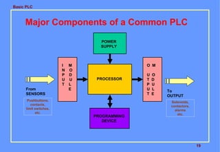
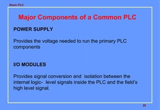
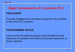
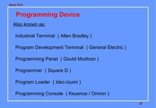

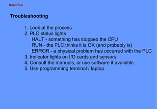
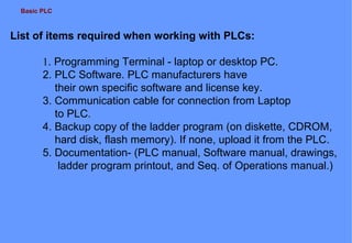
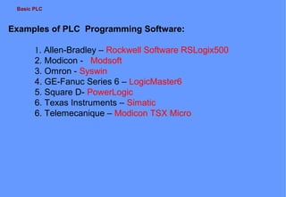

This document provides an overview of a basic training course on programmable logic controllers (PLCs). It describes the course objectives which are to understand the major PLC components, interpret specifications, troubleshoot PLCs, convert relay logic to PLC programming, and operate and program a PLC for applications. The course covers the history of PLCs, components like the CPU and I/O system, programming concepts, applications, and troubleshooting. It also provides examples of PLC programming for mixing tank controls.