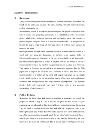
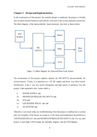
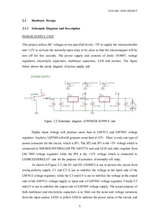
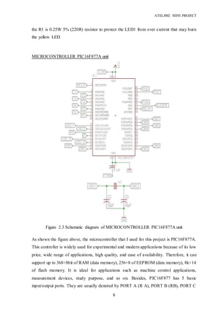
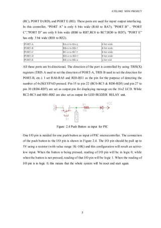
SlideShare a Scribd company logo
ATEL3002 MINI PROJECT
1
Chapter 1 Introduction
1.1 Background
Today, we are living in the in the of embedded systems surrounded by devices that
based on the embedded systems like cars, washing machine microwave-oven,
medical equipment's etc.
An embedded system is a computer system designed for specific control functions
often with real time computing constraints. It is embedded as part of a complete
device which often including hardware and mechanical parts. By contrast, a
general-purpose computer, such as a personal computer (PC), is designed to be
flexible to meet a wide range of end user needs. It controls many devices in
common use today.
One of prominent example of an embedded system is a microcontroller, which is a
small and tiny computer designated to perform some specific tasks. A
Microcontroller program (firmware) is the one, which decides what functionality
the microcontroller provides to a user. A program that has the ability to run on a
microcontroller without the need of an operating system is called as a firmware.
That means, a firmware has the privilege to access the hardware directly. This
paper tries to explain an electronic lock firmware in detail. The basic idea of
microcontroller is to collect all the input and output peripherals in one simple
circuit, which represent the microcontroller instead of the large and sophisticated
computer with microprocessor and large numbers of peripherals. The firmware
directly deals with peripherals and Input / Output ports to give complete
functionality of microcontroller.
1.2 Problem Definition
Nowadays, the digital door lock system is available at anywhere, but not all the
people can afford to buy it. This is because the price for this system is quite
expensive and not all people willing to spend lots of money to purchase this system.
They are much to purchase traditional door lock which is cheaper and easier to use
than digital door lock. While these traditional devices have their limitations too,
one of the major problems is people easily forget where’s the location of the key
actually put. They have to waste their time as they have to find the key for door
lock whole day to switch on the door. This is mainly happen on the person who is
ATEL3002 MINI PROJECT
2
having a bad memory. Therefore, they have to make lots of duplicate key for
backup usage and this may cause wastage of money too.
1.3 Project aims
Based on the problem stated above, my proposed system can easily solve of this
problems. My project aims to minimise the problem of forgetful person that he or
she just only needed to memorise the default password for digital door lock. And
digital door lock is much reliable and efficient than traditional ones as it offer
higher security level. This is because the only owner knows his/her default
password while other intruders do not know the password is. And also, my
proposed system is using with low cost but high quality of component such as
microcontroller which is main “brain” of the system and 16x2 LCD which is
display the message to user.
1.4 Project Objectives
i) To provide a security lock that is efficient and reliable, at cheaper price in
comparison with traditional devices.
ii) To provide opportunity of textual displays as compared to conventional
ones which only show digits.
1.5 Project Outline
As I proposed the mini project, I will update my schedule and progress to my
supervisor, Mr Tai See Chew for future progress and outline. He gives me some
advice and recommendation to improve my proposed mini project. After finish my
mini project, I write this report about the progress and how I develop and
troubleshoot my mini project. Below is the schedule how my mini project is being
organised:
ATEL3002 MINI PROJECT
3
Progress achieved  Week 1 2 3 4 5 6 7 8 9 10 11 12 13 14
Project specification. √
Proposal write-up and submission. √ √
Construct minimal circuitry for
microcontroller circuitry and verify
operation
√ √
Develop interfacing circuitry for
2x16 LCD and verify operation
√
Develop interfacing circuitry for 4x4
Keypad
√
Develop interfacing circuitry for
power supply for whole circuit
√
Develop an application for locking
door mechanism
√ √
System integration, characterizing,
testing & verification.
√ √ √ √ √
Prototype fabrication √ √ √
Report write-up √ √ √ √ √ √ √
Report submission √
Presentation √
ATEL3002 MINI PROJECT
4
Chapter 2 Designand Implementation
In the construction of this project, the modular design is employed, the project is divided
into two parts namely hardware and software with each of the section analysed extensively.
The block diagram of the microcontroller based electronic door lock is shown below:
The construction of this project employs majorly the PIC16F877A microcontroller for
several reasons. Firstly, it is operated on a +5V DC supply and draws very little current.
Furthermore, it has a very low power dissipation and high speed of operation. For this
project, I had separated it into 5 parts which is
i) POWER SUPPLY unit,
ii) MICROCONTROLLER PIC16F877A unit,
iii) LCD unit,
iv) LED BUZZER RELAY unit and
v) 4x3 KEYPAD unit,
Therefore, I can easily make my troubleshooting when the project is malfunction at certain
part. For examples, if the buzzer no sound on, I will check and troubleshoot the problem on
LED BUZZER RELAY unit and MICROCONTROLLER PIC16F877A unit. For my mini
project, I used Eagle 6.40 to design the schematic diagram and also PCB diagram.
Figure 2.1 Block Diagram for Password Door Lock System
4X4
Keypad
PIC
16F877A
Buzzer
Relay
LCD
Door
Lock
ATEL3002 MINI PROJECT
5
2.1 Hardware Design
2.1.1 Schematic Diagram and Description
POWER SUPPLY UNIT
This project utilizes DC voltages at two specified levels; +5V to supply the microcontroller
and +12V to activate the normally-open relay to be close so that the electromagnet will be
turn off for few seconds. The power supply unit consists of diode 1N4007, voltage
regulators, electrolytic capacitors, multilayer capacitors, LED and resistor. The figure
below shown the circuit diagram of power supply unit
Higher input voltage will produce more heat at LM7812 and LM7805 voltage
regulator. Anyhow, LM7805will still generate some heat at 12V. There is only one type of
power connector for the circuit, which is JP1. The JP2 and JP3 is the +5V voltage which is
connected to MICROCONTROLLER PIC16F877A unit and LCD unit after regulate from
LM 7805 voltage regulator while the JP4 is the +12V voltage which is connected to
LEDBUZZERRELAY unit for the purpose of activation of normally-off relay.
As shown in Figure 2.2, the D1 and D2 (1N4007) is use to protect the circuit from
wrong polarity supply. C1 and C2 is use to stabilize the voltage at the input side of the
LM7812 voltage regulator, while the C3 and C4 is use to stabilize the voltage at the output
side of the LM7812 voltage supply or input side of LM7805 voltage regulator. Finally C5
and C6 is use to stabilize the output side of LM7805 voltage supply. The actual purpose of
both multilayer and electrolytic capacitors is to filter out the noise and voltage variations
from the input source. LED1 is yellow LED to indicate the power status of the circuit, and
Figure 2.2 Schematic diagram of POWER SUPPLY unit
ATEL3002 MINI PROJECT
6
the R1 is 0.25W 5% (220R) resistor to protect the LED1 from over current that may burn
the yellow LED.
MICROCONTROLLER PIC16F877A unit
As shown the figure above, the microcontroller that I used for this project is PIC16F877A.
This controller is widely used for experimental and modern applications because of its low
price, wide range of applications, high quality, and ease of availability. Therefore, it can
support up to 368×8bit of RAM (data memory), 256×8 of EEPROM (data memory), 8k×14
of flash memory. It is ideal for applications such as machine control applications,
measurement devices, study purpose, and so on. Besides, PIC16F877 has 5 basic
input/output ports. They are usually denoted by PORT A (R A), PORT B (RB), PORT C
Figure 2.3 Schematic diagram of MICROCONTROLLER PIC16F877A unit
ATEL3002 MINI PROJECT
7
(RC), PORT D (RD), and PORT E (RE). These ports are used for input/ output interfacing.
In this controller, “PORT A” is only 6 bits wide (RA0 to RA7), ”PORT B” , “PORT
C”,”PORT D” are only 8 bits wide (RB0 to RB7,RC0 to RC7,RD0 to RD7), ”PORT E”
has only 3 bit wide (RE0 to RE2).
All these ports are bi-directional. The direction of the port is controlled by using TRIS(X)
registers (TRIS A used to set the direction of PORT-A, TRIS B used to set the direction for
PORT-B, etc.). I set RA0-RA5 and RE0-RE1 as the pin for the purpose of detecting the
number of 4x3KEYPAD pressed. Pin 15 to pin 22 (RC0-RC3 & RD0-RD3) and pin 27 to
pin 30 (RD4-RD7) are set as output pin for displaying message on the 16x2 LCD. While
RC2-RC3 and RB1-RB2 are also set as output for LED BUZZER RELAY unit.
One I/O pin is needed for one push button as input of PIC microcontroller. The connection
of the push button to the I/O pin is shown in Figure 2.4. The I/O pin should be pull up to
5V using a resistor (with value range 1K-10K) and this configuration will result an active-
low input. When the button is being pressed, reading of I/O pin will be in logic 0, while
when the button is not pressed, reading of that I/O pin will be logic 1. When the reading of
I/O pin is in logic 0, this means that the whole system will be reset and start again.
Figure 2.4 Push Button as input for PIC
microcontroller
ATEL3002 MINI PROJECT
8
LCD unit
Figure 2.5 is a 2X16 character LCD. LCD connection pins and function of each pin are
shown in table below:
Pin Name Pin Function Connection
1 VSS Ground GND
2 VCC Positive supply for LCD VCC
3 VEE Brightness adjust CONT
4 RS Select register, instruction or data register RS
5 R/W Select read or write GND
6 E Start data read or write E
7 DB0 Data pin bus DB0
8 DB1 Data pin bus DB1
9 DB2 Data pin bus DB2
10 DB3 Data pin bus DB3
11 DB4 Data pin bus DB4
12 DB5 Data pin bus DB5
13 DB6 Data pin bus DB6
14 DB7 Data pin bus DB7
15 LED+ Backlight positiveinput VCC
16 LED- Backlight negative input GND
Figure 2.5 Schematic diagram of LCD unit
microcontroller
ATEL3002 MINI PROJECT
9
LED BUZZER RELAY unit
One I/O pin is needed for one LED as output of PIC microcontroller. The connection for a
LED to I/O pin is shown in the schematic above. The function of R1 and R2 is to protect
the LED from over current that will burn the red and green light LED. When the output is
in logic 1, the LED will ON, while the output is in logic 0, the LED will OFF. The relay
used for the project consists of 8 pins, 2 pins is the 2 end of the coil, 2 is COM, 2 is NO
and 2 is NC that shown in Figure 2.6
One end of the coil is connected to 12V and another end is connected to an NPN transistor
(2N2222) to amplify the small IC current to larger value required for the relay coil. COM
pin is connected to 12V and NO is connected to a 2510 2-pin connector which is provided
to locate the door magnetic lock. Buzzer can be connected to any I/O pin of
microcontroller PIC16F877A as output.
Figure 2.5 Schematic diagram of LED BUZZER RELAY unit
microcontroller
Figure 2.6 Illustration of GoodSky DC 12V Relay
microcontroller
ATEL3002 MINI PROJECT
10
4x3 KEYPAD unit
Keypad is an array of switch. There will be 2 wires connected each time a button is pressed.
For example; when button ‘1’ is pressed, R1 and R5 is connected. There is no connection
between rows and also columns. The button makes it connect together. In this project, the
keypad consists of 7 pins. The 7 pins remaining are separated into 2 groups, 4 pins (C1-C3)
connect to input and 4 pins (R1-R4) connect to the output. Input must be pull high to 5V
using a resistor and this configuration will result an active-low input.
Figure 2.7 Schematic diagram of 4x3 KEYPAD unit
micontroller
ATEL3002 MINI PROJECT
11
2.1.2 PCB Diagram and Design
Figure 2.9 PCB diagram of
MICROCONTROLLER PIC16F877A unit
(top view)
Figure 2.8 PCB diagram of POWER
SUPPLY unit (top view)
Figure 2.10 PCB diagram of LED
BUZZER RELAY unit (top view)
Figure 2.11 PCB diagram of LCD unit
(top view)
ATEL3002 MINI PROJECT
12
2.2 Software Design
The software is designed in order to support the effectiveness of the hardware device. The
complex and intricate operating routine of the software is achieved by writing the program
in modules starting with the program algorithm, followed by the program flowchart shown
in Figure 2.18. The software was written in C language, and was written in sections for
easy debugging and troubleshooting. Each section is tailored to meet the duty that will be
imposed on the corresponding hardware unit.
Configuration of program
Figure 2.12 shows the configuration of the program and the
initial value for certain variables and port pins. The
ADCON1 register is configured with the binary value of
‘00000110’ to change the entire port A pins into digital I/O
instead of analog I/O. All the port A/B/C/D&E are bi-
directional port meaning that they can be input or output.
The corresponding data direction register are
TRISA/B/C/D&E. Setting a TRIS bit (=1) will let the
corresponding port bit an input. Clearing a TRIS bit (=0)
will let the corresponding port bit an output. For an example,
refer to the source code in Figure 1, TRISA is given the
value ‘11001111’ in binary. This means port A pin 4&5 are
output while the rest are inputs.
Configuration of LCD
The configuration of the LCD is shown in Figure
2.13.
Any words can be sent and displayed by using
the LCD function (refer to sample program).
‘lcd_goto’ function decides from which column
the string start.
Figure 2.12
Figure 2.13
ATEL3002 MINI PROJECT
13
Scanning of Keypad
Coding in Figure 2.14 shows a simple method to read the keypad. Program will scan row
and column of keypad to read 4 digit password entered by user (Refer Figure 2.15 and
Figure 2.16). First, clear the output pin RE1 and set the others. Go to a ‘scancolumn1’
function shown in Figure 2.16. If the RA0 (input) detect a 0, it means the ‘1’ key is pressed
(please refer to the general description of keypad). Now, clear the second column which is
pin RE0 and set the others. Go to ‘scancolumn2’ function to scan whether the key ‘4’, ‘5’,
or ‘6’ is being pressed. If RA1 (input pin) detects a 0, meaning that the key ‘5’ is pressed.
Clear RA5 and set the others and go for ‘scancolumn3’ function to detect the key ‘7’, ‘8’,
or ‘9’. At last, clear RA4 and go for ‘scancolumn4’ function.
Figure 2.14
ATEL3002 MINI PROJECT
14
Refer to the scancolumn1 function in Figure 2.16, if RA0 pin equal to ‘0’ (‘1’ key is
pressed), the program under the “if” command will be activated. First, the “while”
command will wait the ‘1’ to be released to make sure the program under the “if”
command will only run one time for a press. After that, the words on LCD screen will be
cleared if the ‘password_count’ variable is equal to zero. The purpose of the
‘password_count’ variable is to let the LCD screen clear when the first digit is entered. The
LCD will display the symbol ‘*’ to tell user that the first digit is already been entered. Next,
‘1’ value is stall at the keyin_char array. After that, password_count will increase 1 for 1
digit entered. Program will continue the process until password_count variable is equal to 4
or 4 digit password has been entered by user.
Figure 2.15 Figure 2.16
ATEL3002 MINI PROJECT
15
Comparing result
After all 4 digits have been entered, program will compare value in keyin_char array with
value in stalled_char array. Look at Figure 2.17, after the ‘password_count’ variable count
to 4, the program will compare value in keyin_char array with value in stalled_char array.
If value in keyin_char array is same with value in stalled_char array, LCD will display
‘Accessed’, ‘led_green’ will ON, buzzer will beep once and relay will activated. If value in
keyin_char array is different with value in stalled_char array, LCD will display ‘Denied’,
‘led_red’ will ON and buzzer will beep twice.
Figure 2.17
ATEL3002 MINI PROJECT
16
Figure 2.18 Flow chart of overall system
Scanning Process.
Enter 4-digit password.
Yes No
Yes No
Compare key in value with
stall value
1st Key In
value
==
1st Stall
value
1st Key In
value
!=
1st Stall
value
1st digit
correct?
Yes No
2nd Key In
value
==
2nd Stall
value
2nd Key In
value
!=
2nd Stall
value
2nd digit
correct?
Yes No
3rd Key In
value
==
3rd Stall
value
3rd Key In
value
!=
3rd Stall
value
3rd digit
correct?
Yes No
4th Key In
value
==
4th Stall
value
4th Key In
value
!=
4th Stall
value
4th digit
correct?
 LCD shows
“Accessed”.
 Green LED on.
 Buzzer beep once.
 Relay activated.
 LCD shows
“Denied”.
 Red LED on.
 Buzzer beep twice.
Result?
ATEL3002 MINI PROJECT
17
Chapter 3 Test, Resultand Discussion
After construction of the entire system, the hardware parts including the POWER SUPPLY
unit, the LCD unit, the KEYPAD and the LED BUZZER RELAY unit were tested on the
bread board while the software debugging was done using the MPLAB IDE.
3.1 POWER SUPPLY unit
From Figure 2.19, the yellow LED turns on to indicate the power is supplied. The value
output voltage of LM7805 and LM 7812 are also measured and recorded by using
voltmeter based on Figure 2.20 and 2.21.
3.2 LCD unit
To test LCD unit, connect to the MICROCONTROLLER PIC16F877A unit and the make
sure the connection of the wire is correct connected. If the wire is connected correctly, the
LCD will display the message that what your program inside the microcontroller. (The
figure below is the program imported to microcontroller before transfer to PCB board.)
Figure 2.20 Figure 2.21 show the
value of output voltage
of LM 7805
Figure 2.19
Figure 2.22 Figure 2.23 Figure 2.24
ATEL3002 MINI PROJECT
18
3.3 KEYPAD unit
To test the KEYPAD unit, continuity test is taken to checking of an electric circuit to see
if current flows (that it is in fact a complete circuit). Based on Figure 2.7, when a key for
example ‘1’ is pressed, the 2 pin R4 and C3 will be shorted. I tested it by using multi-meter,
one of the probe will ‘touch’ the R4 and the another probe will ‘touch’ the C3(as shown in
Figure 2.24), the buzzer sounds on, the LED turns on at the same time and the display of
multi-meter with low value mean that is a connection between them.
3.4 LED BUZZER RELAY unit
At the same time you key in correct password, the green LED will turn on. On the other
side, the red LED will turn on when password is not matched with default password.
Figure 2.24 Figure 2.26Figure 2.25
Figure 2.28Figure 2.27
ATEL3002 MINI PROJECT
19
Chapter 4 Conclusionand Recommendation
4.1 Conclusions
In conclusion, the project worked and had met with the objectives set prior to the start of
the processes. The PIC is able to process the input data and display output data correctly
and accurately in breadboard. Unfortunately, the project had failed during the transferring
process of PCB.
During the process of transferring into PCB, a lot of important stuffs need to be take note.
For my opinion, we have to drill the pad of each component in PCB first and then draw
bigger the pad before etching it. This is because the copper pads which you draw by your
permanent marker pen are too small that will be spoiled during the drilling process. As a
result, the solder lead cannot stick on the copper pad and we need to melt large amount of
solder lead to make sure the leg of the component is connected to others. And this may
cause the beautifulness of the whole PCB.
In between, there are a lot of problems to be solved such as programming problem, circuit
connection problem, component defective and so on. All these problems are hard to be
identified with its death root causes but luckily with the help of some friends and
guidance from lecturers, the problems are solved.
Finally, I have also learned the importance of certain components to be installed to the
board. Before this, it is hard to understand why some components have to appear on the
board when its main function is not really relevant. This will improve my knowledge in
further use. I’m glad in developing a mini project.
ATEL3002 MINI PROJECT
20
4.2 Recommendation
Due to the lacking of time, the limitation of this system is that the password set by the
user is stored in the RAM and hence it is lost when the supply is switched off. When the
supply is switched on again, the system is reset with the default password 1234. Therefore,
further improvement is that adding the feature of password can be changed by the user
and the changed password will be saved eternally in the EEPROM after the power is
switch off.
ATEL3002 MINI PROJECT
21
References
Books
[1] Muhammad Ali Mazidi, Janice G. Mazidi, Rolin D. McKinlay, “The 8051
Microcontroller and Embedded Systems”, Second Edition, 2008.
Data Sheets:
[2] “PIC16F87XA 28/40/44-Pin Enhanced Flash Microcontrollers”, Data Sheet,
MicroChip
[3] “LCD HD44780”, Data Sheet, Hitachi.
[4] “KA78XX/KA78XXA 3-Terminal 1A Positive Voltage Regulator”, Data Sheet,
FairChild Semicondutor
Internet
[5] Cytron technologies
http://cytron.com.my/
[6] Anshuman Bezborah, “PIC Microcontroller-Based Electronic Lock”,
http://kitsnspares.com/admin/pdffiles/pic%20based%20electronic%20lock.pdf
[7] EAGLE Library – List of most commonly used electronics components
http://elecrom.wordpress.com/2009/10/09/eagle-library-list-of-most-commonly-used-
electronics-components/
ATEL3002 MINI PROJECT
22
Appendices
Figure 3.0 Example of Password Door Security

More Related Content

What's hot

Introduction to Power Electronics
Introduction to Power ElectronicsIntroduction to Power Electronics
Introduction to Power Electronics
PaulTheHuman1
 
GSM BASED GAS LEAKAGE DETECTION SYSTEM
GSM BASED GAS LEAKAGE DETECTION SYSTEMGSM BASED GAS LEAKAGE DETECTION SYSTEM
GSM BASED GAS LEAKAGE DETECTION SYSTEM
International Journal of Technical Research & Application
 
NodeMCU ESP8266 workshop 1
NodeMCU ESP8266 workshop 1NodeMCU ESP8266 workshop 1
NodeMCU ESP8266 workshop 1
Andy Gelme
 
Project report on home automation using Arduino
Project report on home automation using Arduino Project report on home automation using Arduino
Project report on home automation using Arduino
AMIT SANPUI
 
AUTONOMOUS LPG GAS SENSOR BOT USING ARDUINO ppt
AUTONOMOUS LPG GAS SENSOR BOT USING ARDUINO pptAUTONOMOUS LPG GAS SENSOR BOT USING ARDUINO ppt
AUTONOMOUS LPG GAS SENSOR BOT USING ARDUINO ppt
Ravi Shankar
 
Fire fighting robot remotely operated by android applications
Fire fighting robot remotely operated by android applicationsFire fighting robot remotely operated by android applications
Fire fighting robot remotely operated by android applications
Edgefxkits & Solutions
 
My Final Year Project - Individual Control Home Automation System
My Final Year Project - Individual Control Home Automation SystemMy Final Year Project - Individual Control Home Automation System
My Final Year Project - Individual Control Home Automation System
Michael Olafusi
 
Summer Internship Report For PLC Programming of Traffic light through Ladder ...
Summer Internship Report For PLC Programming of Traffic light through Ladder ...Summer Internship Report For PLC Programming of Traffic light through Ladder ...
Summer Internship Report For PLC Programming of Traffic light through Ladder ...
Aman Gupta
 
Transformer Parameters Monitoring System using MATLAB Simulink
Transformer Parameters Monitoring System using MATLAB SimulinkTransformer Parameters Monitoring System using MATLAB Simulink
Transformer Parameters Monitoring System using MATLAB Simulink
Dr. Amarjeet Singh
 
Digital notice board saiteja ppt
Digital notice board saiteja pptDigital notice board saiteja ppt
Digital notice board saiteja ppt
Saitejasmart
 
PASSWORD PROTECTED DOOR OPENING SYSTEM BY HEMANTA
PASSWORD PROTECTED DOOR OPENING SYSTEM BY HEMANTAPASSWORD PROTECTED DOOR OPENING SYSTEM BY HEMANTA
PASSWORD PROTECTED DOOR OPENING SYSTEM BY HEMANTA
HEMANTA SAHU
 
Home automation ppt
Home automation pptHome automation ppt
Home automation ppt
Anshul97842474929
 
B.Tech.Final Year ECE Project Report on Ultrasonic distance measure robot
B.Tech.Final Year ECE Project Report on Ultrasonic distance measure robotB.Tech.Final Year ECE Project Report on Ultrasonic distance measure robot
B.Tech.Final Year ECE Project Report on Ultrasonic distance measure robot
Sushant Shankar
 
Temp based fan speed control
Temp based fan speed controlTemp based fan speed control
Temp based fan speed controlSai Malleswar
 
Password based door locking system
Password based door locking systemPassword based door locking system
Password based door locking system
Arjun Singh
 
Introduction of multisim
Introduction of multisimIntroduction of multisim
Introduction of multisim
Abdul Wahab Raza
 
laser security alarm thesis
laser security alarm thesislaser security alarm thesis
laser security alarm thesis
yash kumar singh
 
Automatic Door Opener using PIR Sensor
Automatic Door Opener using PIR SensorAutomatic Door Opener using PIR Sensor
Automatic Door Opener using PIR Sensor
RAGHUVARMA09
 
Input - Output Devices for PLC
Input - Output Devices for PLCInput - Output Devices for PLC
Input - Output Devices for PLC
Arko Saha
 
Project report on the Digital clock using RTC and microcontroller 8051
Project report on the Digital clock using RTC and microcontroller 8051Project report on the Digital clock using RTC and microcontroller 8051
Project report on the Digital clock using RTC and microcontroller 8051
Maulik Sanchela
 

What's hot (20)

Introduction to Power Electronics
Introduction to Power ElectronicsIntroduction to Power Electronics
Introduction to Power Electronics
 
GSM BASED GAS LEAKAGE DETECTION SYSTEM
GSM BASED GAS LEAKAGE DETECTION SYSTEMGSM BASED GAS LEAKAGE DETECTION SYSTEM
GSM BASED GAS LEAKAGE DETECTION SYSTEM
 
NodeMCU ESP8266 workshop 1
NodeMCU ESP8266 workshop 1NodeMCU ESP8266 workshop 1
NodeMCU ESP8266 workshop 1
 
Project report on home automation using Arduino
Project report on home automation using Arduino Project report on home automation using Arduino
Project report on home automation using Arduino
 
AUTONOMOUS LPG GAS SENSOR BOT USING ARDUINO ppt
AUTONOMOUS LPG GAS SENSOR BOT USING ARDUINO pptAUTONOMOUS LPG GAS SENSOR BOT USING ARDUINO ppt
AUTONOMOUS LPG GAS SENSOR BOT USING ARDUINO ppt
 
Fire fighting robot remotely operated by android applications
Fire fighting robot remotely operated by android applicationsFire fighting robot remotely operated by android applications
Fire fighting robot remotely operated by android applications
 
My Final Year Project - Individual Control Home Automation System
My Final Year Project - Individual Control Home Automation SystemMy Final Year Project - Individual Control Home Automation System
My Final Year Project - Individual Control Home Automation System
 
Summer Internship Report For PLC Programming of Traffic light through Ladder ...
Summer Internship Report For PLC Programming of Traffic light through Ladder ...Summer Internship Report For PLC Programming of Traffic light through Ladder ...
Summer Internship Report For PLC Programming of Traffic light through Ladder ...
 
Transformer Parameters Monitoring System using MATLAB Simulink
Transformer Parameters Monitoring System using MATLAB SimulinkTransformer Parameters Monitoring System using MATLAB Simulink
Transformer Parameters Monitoring System using MATLAB Simulink
 
Digital notice board saiteja ppt
Digital notice board saiteja pptDigital notice board saiteja ppt
Digital notice board saiteja ppt
 
PASSWORD PROTECTED DOOR OPENING SYSTEM BY HEMANTA
PASSWORD PROTECTED DOOR OPENING SYSTEM BY HEMANTAPASSWORD PROTECTED DOOR OPENING SYSTEM BY HEMANTA
PASSWORD PROTECTED DOOR OPENING SYSTEM BY HEMANTA
 
Home automation ppt
Home automation pptHome automation ppt
Home automation ppt
 
B.Tech.Final Year ECE Project Report on Ultrasonic distance measure robot
B.Tech.Final Year ECE Project Report on Ultrasonic distance measure robotB.Tech.Final Year ECE Project Report on Ultrasonic distance measure robot
B.Tech.Final Year ECE Project Report on Ultrasonic distance measure robot
 
Temp based fan speed control
Temp based fan speed controlTemp based fan speed control
Temp based fan speed control
 
Password based door locking system
Password based door locking systemPassword based door locking system
Password based door locking system
 
Introduction of multisim
Introduction of multisimIntroduction of multisim
Introduction of multisim
 
laser security alarm thesis
laser security alarm thesislaser security alarm thesis
laser security alarm thesis
 
Automatic Door Opener using PIR Sensor
Automatic Door Opener using PIR SensorAutomatic Door Opener using PIR Sensor
Automatic Door Opener using PIR Sensor
 
Input - Output Devices for PLC
Input - Output Devices for PLCInput - Output Devices for PLC
Input - Output Devices for PLC
 
Project report on the Digital clock using RTC and microcontroller 8051
Project report on the Digital clock using RTC and microcontroller 8051Project report on the Digital clock using RTC and microcontroller 8051
Project report on the Digital clock using RTC and microcontroller 8051
 

Viewers also liked

Password based door lock system using 8051 microcontroller final report
Password based door lock system using 8051 microcontroller final reportPassword based door lock system using 8051 microcontroller final report
Password based door lock system using 8051 microcontroller final report
Chinaraja Baratam
 
Smart digital door locking system
Smart digital door locking systemSmart digital door locking system
Smart digital door locking system
VISHAL NAGAR
 
Smart door project ppt shivnaresh likhar
Smart door project ppt shivnaresh likharSmart door project ppt shivnaresh likhar
Smart door project ppt shivnaresh likhar
Shivnaresh Likhar
 
Password based door locksystem
Password  based door locksystemPassword  based door locksystem
Password based door locksystem
UVSofts Technologies
 
Prototyping and Usability Testing your designs
Prototyping and Usability Testing your designsPrototyping and Usability Testing your designs
Prototyping and Usability Testing your designs
Elizabeth Snowdon
 

Viewers also liked (7)

Password based door lock system using 8051 microcontroller final report
Password based door lock system using 8051 microcontroller final reportPassword based door lock system using 8051 microcontroller final report
Password based door lock system using 8051 microcontroller final report
 
Smart digital door locking system
Smart digital door locking systemSmart digital door locking system
Smart digital door locking system
 
Security door lock system
Security door lock system Security door lock system
Security door lock system
 
Smart door project ppt shivnaresh likhar
Smart door project ppt shivnaresh likharSmart door project ppt shivnaresh likhar
Smart door project ppt shivnaresh likhar
 
Password based door locksystem
Password  based door locksystemPassword  based door locksystem
Password based door locksystem
 
Prototyping and Usability Testing your designs
Prototyping and Usability Testing your designsPrototyping and Usability Testing your designs
Prototyping and Usability Testing your designs
 
Project ppt
Project pptProject ppt
Project ppt
 

Similar to Report (Electromagnetic Password Door Lock System)

Home automation control system using dtmf technology
Home automation control system using dtmf technologyHome automation control system using dtmf technology
Home automation control system using dtmf technology
Govind Ekshinge
 
Industrial Process Management Using LabVIEW
Industrial Process Management Using LabVIEWIndustrial Process Management Using LabVIEW
Industrial Process Management Using LabVIEW
IOSR Journals
 
Industrial Process Management Using LabVIEW
Industrial Process Management Using LabVIEWIndustrial Process Management Using LabVIEW
Industrial Process Management Using LabVIEW
IOSR Journals
 
Home automation
Home automationHome automation
Home automation
Moorthy kvn
 
Project Report On Micro-controller Embedded System
Project Report On Micro-controller Embedded SystemProject Report On Micro-controller Embedded System
Project Report On Micro-controller Embedded System
Rkrishna Mishra
 
Report on Embedded Based Home security system
Report on Embedded Based Home security systemReport on Embedded Based Home security system
Report on Embedded Based Home security system
NIT srinagar
 
Project report on dtmf based door opening system
Project report on  dtmf based door opening systemProject report on  dtmf based door opening system
Project report on dtmf based door opening system
Mukul Mohal
 
Smart home
Smart homeSmart home
Smart home
Moorthy kvn
 
Smart home copy
Smart home   copySmart home   copy
Smart home copy
Moorthy kvn
 
Smart home
Smart homeSmart home
Smart home
Moorthy kvn
 
Minor_project.ppt.pdf
Minor_project.ppt.pdfMinor_project.ppt.pdf
Minor_project.ppt.pdf
Uttamsharma576508
 
electronic voting machine by rfid
electronic voting machine by rfidelectronic voting machine by rfid
electronic voting machine by rfidSaurabh Uniyal
 
IRJET- Items’ Filling System Prototype with Sorting System According to the C...
IRJET- Items’ Filling System Prototype with Sorting System According to the C...IRJET- Items’ Filling System Prototype with Sorting System According to the C...
IRJET- Items’ Filling System Prototype with Sorting System According to the C...
IRJET Journal
 
microcontroller and embedded system
microcontroller and embedded systemmicrocontroller and embedded system
microcontroller and embedded systempradeep rana
 
Micro controller based projects
Micro controller based projectsMicro controller based projects
Micro controller based projectsFajar Isnanto
 
Home Appliances Controlling using Android Mobile via Bluetooth
Home Appliances Controlling using Android Mobile via BluetoothHome Appliances Controlling using Android Mobile via Bluetooth
Home Appliances Controlling using Android Mobile via BluetoothMOKTARI MOSTOFA
 
Kalyan abstrct googl
Kalyan abstrct googlKalyan abstrct googl
Kalyan abstrct googldevakalyan143
 
summer training report (2)
summer training report (2)summer training report (2)
summer training report (2)Kavya Gupta
 
Wireless appliances control report
Wireless appliances control reportWireless appliances control report
Wireless appliances control report
engineerssolution
 
Bidirect visitor counter
Bidirect visitor counterBidirect visitor counter
Bidirect visitor counter
Electric&elctronics&engineeering
 

Similar to Report (Electromagnetic Password Door Lock System) (20)

Home automation control system using dtmf technology
Home automation control system using dtmf technologyHome automation control system using dtmf technology
Home automation control system using dtmf technology
 
Industrial Process Management Using LabVIEW
Industrial Process Management Using LabVIEWIndustrial Process Management Using LabVIEW
Industrial Process Management Using LabVIEW
 
Industrial Process Management Using LabVIEW
Industrial Process Management Using LabVIEWIndustrial Process Management Using LabVIEW
Industrial Process Management Using LabVIEW
 
Home automation
Home automationHome automation
Home automation
 
Project Report On Micro-controller Embedded System
Project Report On Micro-controller Embedded SystemProject Report On Micro-controller Embedded System
Project Report On Micro-controller Embedded System
 
Report on Embedded Based Home security system
Report on Embedded Based Home security systemReport on Embedded Based Home security system
Report on Embedded Based Home security system
 
Project report on dtmf based door opening system
Project report on  dtmf based door opening systemProject report on  dtmf based door opening system
Project report on dtmf based door opening system
 
Smart home
Smart homeSmart home
Smart home
 
Smart home copy
Smart home   copySmart home   copy
Smart home copy
 
Smart home
Smart homeSmart home
Smart home
 
Minor_project.ppt.pdf
Minor_project.ppt.pdfMinor_project.ppt.pdf
Minor_project.ppt.pdf
 
electronic voting machine by rfid
electronic voting machine by rfidelectronic voting machine by rfid
electronic voting machine by rfid
 
IRJET- Items’ Filling System Prototype with Sorting System According to the C...
IRJET- Items’ Filling System Prototype with Sorting System According to the C...IRJET- Items’ Filling System Prototype with Sorting System According to the C...
IRJET- Items’ Filling System Prototype with Sorting System According to the C...
 
microcontroller and embedded system
microcontroller and embedded systemmicrocontroller and embedded system
microcontroller and embedded system
 
Micro controller based projects
Micro controller based projectsMicro controller based projects
Micro controller based projects
 
Home Appliances Controlling using Android Mobile via Bluetooth
Home Appliances Controlling using Android Mobile via BluetoothHome Appliances Controlling using Android Mobile via Bluetooth
Home Appliances Controlling using Android Mobile via Bluetooth
 
Kalyan abstrct googl
Kalyan abstrct googlKalyan abstrct googl
Kalyan abstrct googl
 
summer training report (2)
summer training report (2)summer training report (2)
summer training report (2)
 
Wireless appliances control report
Wireless appliances control reportWireless appliances control report
Wireless appliances control report
 
Bidirect visitor counter
Bidirect visitor counterBidirect visitor counter
Bidirect visitor counter
 

Recently uploaded

AKS UNIVERSITY Satna Final Year Project By OM Hardaha.pdf
AKS UNIVERSITY Satna Final Year Project By OM Hardaha.pdfAKS UNIVERSITY Satna Final Year Project By OM Hardaha.pdf
AKS UNIVERSITY Satna Final Year Project By OM Hardaha.pdf
SamSarthak3
 
ethical hacking in wireless-hacking1.ppt
ethical hacking in wireless-hacking1.pptethical hacking in wireless-hacking1.ppt
ethical hacking in wireless-hacking1.ppt
Jayaprasanna4
 
weather web application report.pdf
weather web application report.pdfweather web application report.pdf
weather web application report.pdf
Pratik Pawar
 
Top 10 Oil and Gas Projects in Saudi Arabia 2024.pdf
Top 10 Oil and Gas Projects in Saudi Arabia 2024.pdfTop 10 Oil and Gas Projects in Saudi Arabia 2024.pdf
Top 10 Oil and Gas Projects in Saudi Arabia 2024.pdf
Teleport Manpower Consultant
 
Standard Reomte Control Interface - Neometrix
Standard Reomte Control Interface - NeometrixStandard Reomte Control Interface - Neometrix
Standard Reomte Control Interface - Neometrix
Neometrix_Engineering_Pvt_Ltd
 
Railway Signalling Principles Edition 3.pdf
Railway Signalling Principles Edition 3.pdfRailway Signalling Principles Edition 3.pdf
Railway Signalling Principles Edition 3.pdf
TeeVichai
 
NO1 Uk best vashikaran specialist in delhi vashikaran baba near me online vas...
NO1 Uk best vashikaran specialist in delhi vashikaran baba near me online vas...NO1 Uk best vashikaran specialist in delhi vashikaran baba near me online vas...
NO1 Uk best vashikaran specialist in delhi vashikaran baba near me online vas...
Amil Baba Dawood bangali
 
Industrial Training at Shahjalal Fertilizer Company Limited (SFCL)
Industrial Training at Shahjalal Fertilizer Company Limited (SFCL)Industrial Training at Shahjalal Fertilizer Company Limited (SFCL)
Industrial Training at Shahjalal Fertilizer Company Limited (SFCL)
MdTanvirMahtab2
 
Sachpazis:Terzaghi Bearing Capacity Estimation in simple terms with Calculati...
Sachpazis:Terzaghi Bearing Capacity Estimation in simple terms with Calculati...Sachpazis:Terzaghi Bearing Capacity Estimation in simple terms with Calculati...
Sachpazis:Terzaghi Bearing Capacity Estimation in simple terms with Calculati...
Dr.Costas Sachpazis
 
WATER CRISIS and its solutions-pptx 1234
WATER CRISIS and its solutions-pptx 1234WATER CRISIS and its solutions-pptx 1234
WATER CRISIS and its solutions-pptx 1234
AafreenAbuthahir2
 
Vaccine management system project report documentation..pdf
Vaccine management system project report documentation..pdfVaccine management system project report documentation..pdf
Vaccine management system project report documentation..pdf
Kamal Acharya
 
ASME IX(9) 2007 Full Version .pdf
ASME IX(9)  2007 Full Version       .pdfASME IX(9)  2007 Full Version       .pdf
ASME IX(9) 2007 Full Version .pdf
AhmedHussein950959
 
LIGA(E)11111111111111111111111111111111111111111.ppt
LIGA(E)11111111111111111111111111111111111111111.pptLIGA(E)11111111111111111111111111111111111111111.ppt
LIGA(E)11111111111111111111111111111111111111111.ppt
ssuser9bd3ba
 
DESIGN A COTTON SEED SEPARATION MACHINE.docx
DESIGN A COTTON SEED SEPARATION MACHINE.docxDESIGN A COTTON SEED SEPARATION MACHINE.docx
DESIGN A COTTON SEED SEPARATION MACHINE.docx
FluxPrime1
 
Final project report on grocery store management system..pdf
Final project report on grocery store management system..pdfFinal project report on grocery store management system..pdf
Final project report on grocery store management system..pdf
Kamal Acharya
 
Democratizing Fuzzing at Scale by Abhishek Arya
Democratizing Fuzzing at Scale by Abhishek AryaDemocratizing Fuzzing at Scale by Abhishek Arya
Democratizing Fuzzing at Scale by Abhishek Arya
abh.arya
 
Automobile Management System Project Report.pdf
Automobile Management System Project Report.pdfAutomobile Management System Project Report.pdf
Automobile Management System Project Report.pdf
Kamal Acharya
 
block diagram and signal flow graph representation
block diagram and signal flow graph representationblock diagram and signal flow graph representation
block diagram and signal flow graph representation
Divya Somashekar
 
Forklift Classes Overview by Intella Parts
Forklift Classes Overview by Intella PartsForklift Classes Overview by Intella Parts
Forklift Classes Overview by Intella Parts
Intella Parts
 
在线办理(ANU毕业证书)澳洲国立大学毕业证录取通知书一模一样
在线办理(ANU毕业证书)澳洲国立大学毕业证录取通知书一模一样在线办理(ANU毕业证书)澳洲国立大学毕业证录取通知书一模一样
在线办理(ANU毕业证书)澳洲国立大学毕业证录取通知书一模一样
obonagu
 

Recently uploaded (20)

AKS UNIVERSITY Satna Final Year Project By OM Hardaha.pdf
AKS UNIVERSITY Satna Final Year Project By OM Hardaha.pdfAKS UNIVERSITY Satna Final Year Project By OM Hardaha.pdf
AKS UNIVERSITY Satna Final Year Project By OM Hardaha.pdf
 
ethical hacking in wireless-hacking1.ppt
ethical hacking in wireless-hacking1.pptethical hacking in wireless-hacking1.ppt
ethical hacking in wireless-hacking1.ppt
 
weather web application report.pdf
weather web application report.pdfweather web application report.pdf
weather web application report.pdf
 
Top 10 Oil and Gas Projects in Saudi Arabia 2024.pdf
Top 10 Oil and Gas Projects in Saudi Arabia 2024.pdfTop 10 Oil and Gas Projects in Saudi Arabia 2024.pdf
Top 10 Oil and Gas Projects in Saudi Arabia 2024.pdf
 
Standard Reomte Control Interface - Neometrix
Standard Reomte Control Interface - NeometrixStandard Reomte Control Interface - Neometrix
Standard Reomte Control Interface - Neometrix
 
Railway Signalling Principles Edition 3.pdf
Railway Signalling Principles Edition 3.pdfRailway Signalling Principles Edition 3.pdf
Railway Signalling Principles Edition 3.pdf
 
NO1 Uk best vashikaran specialist in delhi vashikaran baba near me online vas...
NO1 Uk best vashikaran specialist in delhi vashikaran baba near me online vas...NO1 Uk best vashikaran specialist in delhi vashikaran baba near me online vas...
NO1 Uk best vashikaran specialist in delhi vashikaran baba near me online vas...
 
Industrial Training at Shahjalal Fertilizer Company Limited (SFCL)
Industrial Training at Shahjalal Fertilizer Company Limited (SFCL)Industrial Training at Shahjalal Fertilizer Company Limited (SFCL)
Industrial Training at Shahjalal Fertilizer Company Limited (SFCL)
 
Sachpazis:Terzaghi Bearing Capacity Estimation in simple terms with Calculati...
Sachpazis:Terzaghi Bearing Capacity Estimation in simple terms with Calculati...Sachpazis:Terzaghi Bearing Capacity Estimation in simple terms with Calculati...
Sachpazis:Terzaghi Bearing Capacity Estimation in simple terms with Calculati...
 
WATER CRISIS and its solutions-pptx 1234
WATER CRISIS and its solutions-pptx 1234WATER CRISIS and its solutions-pptx 1234
WATER CRISIS and its solutions-pptx 1234
 
Vaccine management system project report documentation..pdf
Vaccine management system project report documentation..pdfVaccine management system project report documentation..pdf
Vaccine management system project report documentation..pdf
 
ASME IX(9) 2007 Full Version .pdf
ASME IX(9)  2007 Full Version       .pdfASME IX(9)  2007 Full Version       .pdf
ASME IX(9) 2007 Full Version .pdf
 
LIGA(E)11111111111111111111111111111111111111111.ppt
LIGA(E)11111111111111111111111111111111111111111.pptLIGA(E)11111111111111111111111111111111111111111.ppt
LIGA(E)11111111111111111111111111111111111111111.ppt
 
DESIGN A COTTON SEED SEPARATION MACHINE.docx
DESIGN A COTTON SEED SEPARATION MACHINE.docxDESIGN A COTTON SEED SEPARATION MACHINE.docx
DESIGN A COTTON SEED SEPARATION MACHINE.docx
 
Final project report on grocery store management system..pdf
Final project report on grocery store management system..pdfFinal project report on grocery store management system..pdf
Final project report on grocery store management system..pdf
 
Democratizing Fuzzing at Scale by Abhishek Arya
Democratizing Fuzzing at Scale by Abhishek AryaDemocratizing Fuzzing at Scale by Abhishek Arya
Democratizing Fuzzing at Scale by Abhishek Arya
 
Automobile Management System Project Report.pdf
Automobile Management System Project Report.pdfAutomobile Management System Project Report.pdf
Automobile Management System Project Report.pdf
 
block diagram and signal flow graph representation
block diagram and signal flow graph representationblock diagram and signal flow graph representation
block diagram and signal flow graph representation
 
Forklift Classes Overview by Intella Parts
Forklift Classes Overview by Intella PartsForklift Classes Overview by Intella Parts
Forklift Classes Overview by Intella Parts
 
在线办理(ANU毕业证书)澳洲国立大学毕业证录取通知书一模一样
在线办理(ANU毕业证书)澳洲国立大学毕业证录取通知书一模一样在线办理(ANU毕业证书)澳洲国立大学毕业证录取通知书一模一样
在线办理(ANU毕业证书)澳洲国立大学毕业证录取通知书一模一样
 

Report (Electromagnetic Password Door Lock System)

  • 1. ATEL3002 MINI PROJECT 1 Chapter 1 Introduction 1.1 Background Today, we are living in the in the of embedded systems surrounded by devices that based on the embedded systems like cars, washing machine microwave-oven, medical equipment's etc. An embedded system is a computer system designed for specific control functions often with real time computing constraints. It is embedded as part of a complete device which often including hardware and mechanical parts. By contrast, a general-purpose computer, such as a personal computer (PC), is designed to be flexible to meet a wide range of end user needs. It controls many devices in common use today. One of prominent example of an embedded system is a microcontroller, which is a small and tiny computer designated to perform some specific tasks. A Microcontroller program (firmware) is the one, which decides what functionality the microcontroller provides to a user. A program that has the ability to run on a microcontroller without the need of an operating system is called as a firmware. That means, a firmware has the privilege to access the hardware directly. This paper tries to explain an electronic lock firmware in detail. The basic idea of microcontroller is to collect all the input and output peripherals in one simple circuit, which represent the microcontroller instead of the large and sophisticated computer with microprocessor and large numbers of peripherals. The firmware directly deals with peripherals and Input / Output ports to give complete functionality of microcontroller. 1.2 Problem Definition Nowadays, the digital door lock system is available at anywhere, but not all the people can afford to buy it. This is because the price for this system is quite expensive and not all people willing to spend lots of money to purchase this system. They are much to purchase traditional door lock which is cheaper and easier to use than digital door lock. While these traditional devices have their limitations too, one of the major problems is people easily forget where’s the location of the key actually put. They have to waste their time as they have to find the key for door lock whole day to switch on the door. This is mainly happen on the person who is
  • 2. ATEL3002 MINI PROJECT 2 having a bad memory. Therefore, they have to make lots of duplicate key for backup usage and this may cause wastage of money too. 1.3 Project aims Based on the problem stated above, my proposed system can easily solve of this problems. My project aims to minimise the problem of forgetful person that he or she just only needed to memorise the default password for digital door lock. And digital door lock is much reliable and efficient than traditional ones as it offer higher security level. This is because the only owner knows his/her default password while other intruders do not know the password is. And also, my proposed system is using with low cost but high quality of component such as microcontroller which is main “brain” of the system and 16x2 LCD which is display the message to user. 1.4 Project Objectives i) To provide a security lock that is efficient and reliable, at cheaper price in comparison with traditional devices. ii) To provide opportunity of textual displays as compared to conventional ones which only show digits. 1.5 Project Outline As I proposed the mini project, I will update my schedule and progress to my supervisor, Mr Tai See Chew for future progress and outline. He gives me some advice and recommendation to improve my proposed mini project. After finish my mini project, I write this report about the progress and how I develop and troubleshoot my mini project. Below is the schedule how my mini project is being organised:
  • 3. ATEL3002 MINI PROJECT 3 Progress achieved Week 1 2 3 4 5 6 7 8 9 10 11 12 13 14 Project specification. √ Proposal write-up and submission. √ √ Construct minimal circuitry for microcontroller circuitry and verify operation √ √ Develop interfacing circuitry for 2x16 LCD and verify operation √ Develop interfacing circuitry for 4x4 Keypad √ Develop interfacing circuitry for power supply for whole circuit √ Develop an application for locking door mechanism √ √ System integration, characterizing, testing & verification. √ √ √ √ √ Prototype fabrication √ √ √ Report write-up √ √ √ √ √ √ √ Report submission √ Presentation √
  • 4. ATEL3002 MINI PROJECT 4 Chapter 2 Designand Implementation In the construction of this project, the modular design is employed, the project is divided into two parts namely hardware and software with each of the section analysed extensively. The block diagram of the microcontroller based electronic door lock is shown below: The construction of this project employs majorly the PIC16F877A microcontroller for several reasons. Firstly, it is operated on a +5V DC supply and draws very little current. Furthermore, it has a very low power dissipation and high speed of operation. For this project, I had separated it into 5 parts which is i) POWER SUPPLY unit, ii) MICROCONTROLLER PIC16F877A unit, iii) LCD unit, iv) LED BUZZER RELAY unit and v) 4x3 KEYPAD unit, Therefore, I can easily make my troubleshooting when the project is malfunction at certain part. For examples, if the buzzer no sound on, I will check and troubleshoot the problem on LED BUZZER RELAY unit and MICROCONTROLLER PIC16F877A unit. For my mini project, I used Eagle 6.40 to design the schematic diagram and also PCB diagram. Figure 2.1 Block Diagram for Password Door Lock System 4X4 Keypad PIC 16F877A Buzzer Relay LCD Door Lock
  • 5. ATEL3002 MINI PROJECT 5 2.1 Hardware Design 2.1.1 Schematic Diagram and Description POWER SUPPLY UNIT This project utilizes DC voltages at two specified levels; +5V to supply the microcontroller and +12V to activate the normally-open relay to be close so that the electromagnet will be turn off for few seconds. The power supply unit consists of diode 1N4007, voltage regulators, electrolytic capacitors, multilayer capacitors, LED and resistor. The figure below shown the circuit diagram of power supply unit Higher input voltage will produce more heat at LM7812 and LM7805 voltage regulator. Anyhow, LM7805will still generate some heat at 12V. There is only one type of power connector for the circuit, which is JP1. The JP2 and JP3 is the +5V voltage which is connected to MICROCONTROLLER PIC16F877A unit and LCD unit after regulate from LM 7805 voltage regulator while the JP4 is the +12V voltage which is connected to LEDBUZZERRELAY unit for the purpose of activation of normally-off relay. As shown in Figure 2.2, the D1 and D2 (1N4007) is use to protect the circuit from wrong polarity supply. C1 and C2 is use to stabilize the voltage at the input side of the LM7812 voltage regulator, while the C3 and C4 is use to stabilize the voltage at the output side of the LM7812 voltage supply or input side of LM7805 voltage regulator. Finally C5 and C6 is use to stabilize the output side of LM7805 voltage supply. The actual purpose of both multilayer and electrolytic capacitors is to filter out the noise and voltage variations from the input source. LED1 is yellow LED to indicate the power status of the circuit, and Figure 2.2 Schematic diagram of POWER SUPPLY unit
  • 6. ATEL3002 MINI PROJECT 6 the R1 is 0.25W 5% (220R) resistor to protect the LED1 from over current that may burn the yellow LED. MICROCONTROLLER PIC16F877A unit As shown the figure above, the microcontroller that I used for this project is PIC16F877A. This controller is widely used for experimental and modern applications because of its low price, wide range of applications, high quality, and ease of availability. Therefore, it can support up to 368×8bit of RAM (data memory), 256×8 of EEPROM (data memory), 8k×14 of flash memory. It is ideal for applications such as machine control applications, measurement devices, study purpose, and so on. Besides, PIC16F877 has 5 basic input/output ports. They are usually denoted by PORT A (R A), PORT B (RB), PORT C Figure 2.3 Schematic diagram of MICROCONTROLLER PIC16F877A unit
  • 7. ATEL3002 MINI PROJECT 7 (RC), PORT D (RD), and PORT E (RE). These ports are used for input/ output interfacing. In this controller, “PORT A” is only 6 bits wide (RA0 to RA7), ”PORT B” , “PORT C”,”PORT D” are only 8 bits wide (RB0 to RB7,RC0 to RC7,RD0 to RD7), ”PORT E” has only 3 bit wide (RE0 to RE2). All these ports are bi-directional. The direction of the port is controlled by using TRIS(X) registers (TRIS A used to set the direction of PORT-A, TRIS B used to set the direction for PORT-B, etc.). I set RA0-RA5 and RE0-RE1 as the pin for the purpose of detecting the number of 4x3KEYPAD pressed. Pin 15 to pin 22 (RC0-RC3 & RD0-RD3) and pin 27 to pin 30 (RD4-RD7) are set as output pin for displaying message on the 16x2 LCD. While RC2-RC3 and RB1-RB2 are also set as output for LED BUZZER RELAY unit. One I/O pin is needed for one push button as input of PIC microcontroller. The connection of the push button to the I/O pin is shown in Figure 2.4. The I/O pin should be pull up to 5V using a resistor (with value range 1K-10K) and this configuration will result an active- low input. When the button is being pressed, reading of I/O pin will be in logic 0, while when the button is not pressed, reading of that I/O pin will be logic 1. When the reading of I/O pin is in logic 0, this means that the whole system will be reset and start again. Figure 2.4 Push Button as input for PIC microcontroller
  • 8. ATEL3002 MINI PROJECT 8 LCD unit Figure 2.5 is a 2X16 character LCD. LCD connection pins and function of each pin are shown in table below: Pin Name Pin Function Connection 1 VSS Ground GND 2 VCC Positive supply for LCD VCC 3 VEE Brightness adjust CONT 4 RS Select register, instruction or data register RS 5 R/W Select read or write GND 6 E Start data read or write E 7 DB0 Data pin bus DB0 8 DB1 Data pin bus DB1 9 DB2 Data pin bus DB2 10 DB3 Data pin bus DB3 11 DB4 Data pin bus DB4 12 DB5 Data pin bus DB5 13 DB6 Data pin bus DB6 14 DB7 Data pin bus DB7 15 LED+ Backlight positiveinput VCC 16 LED- Backlight negative input GND Figure 2.5 Schematic diagram of LCD unit microcontroller
  • 9. ATEL3002 MINI PROJECT 9 LED BUZZER RELAY unit One I/O pin is needed for one LED as output of PIC microcontroller. The connection for a LED to I/O pin is shown in the schematic above. The function of R1 and R2 is to protect the LED from over current that will burn the red and green light LED. When the output is in logic 1, the LED will ON, while the output is in logic 0, the LED will OFF. The relay used for the project consists of 8 pins, 2 pins is the 2 end of the coil, 2 is COM, 2 is NO and 2 is NC that shown in Figure 2.6 One end of the coil is connected to 12V and another end is connected to an NPN transistor (2N2222) to amplify the small IC current to larger value required for the relay coil. COM pin is connected to 12V and NO is connected to a 2510 2-pin connector which is provided to locate the door magnetic lock. Buzzer can be connected to any I/O pin of microcontroller PIC16F877A as output. Figure 2.5 Schematic diagram of LED BUZZER RELAY unit microcontroller Figure 2.6 Illustration of GoodSky DC 12V Relay microcontroller
  • 10. ATEL3002 MINI PROJECT 10 4x3 KEYPAD unit Keypad is an array of switch. There will be 2 wires connected each time a button is pressed. For example; when button ‘1’ is pressed, R1 and R5 is connected. There is no connection between rows and also columns. The button makes it connect together. In this project, the keypad consists of 7 pins. The 7 pins remaining are separated into 2 groups, 4 pins (C1-C3) connect to input and 4 pins (R1-R4) connect to the output. Input must be pull high to 5V using a resistor and this configuration will result an active-low input. Figure 2.7 Schematic diagram of 4x3 KEYPAD unit micontroller
  • 11. ATEL3002 MINI PROJECT 11 2.1.2 PCB Diagram and Design Figure 2.9 PCB diagram of MICROCONTROLLER PIC16F877A unit (top view) Figure 2.8 PCB diagram of POWER SUPPLY unit (top view) Figure 2.10 PCB diagram of LED BUZZER RELAY unit (top view) Figure 2.11 PCB diagram of LCD unit (top view)
  • 12. ATEL3002 MINI PROJECT 12 2.2 Software Design The software is designed in order to support the effectiveness of the hardware device. The complex and intricate operating routine of the software is achieved by writing the program in modules starting with the program algorithm, followed by the program flowchart shown in Figure 2.18. The software was written in C language, and was written in sections for easy debugging and troubleshooting. Each section is tailored to meet the duty that will be imposed on the corresponding hardware unit. Configuration of program Figure 2.12 shows the configuration of the program and the initial value for certain variables and port pins. The ADCON1 register is configured with the binary value of ‘00000110’ to change the entire port A pins into digital I/O instead of analog I/O. All the port A/B/C/D&E are bi- directional port meaning that they can be input or output. The corresponding data direction register are TRISA/B/C/D&E. Setting a TRIS bit (=1) will let the corresponding port bit an input. Clearing a TRIS bit (=0) will let the corresponding port bit an output. For an example, refer to the source code in Figure 1, TRISA is given the value ‘11001111’ in binary. This means port A pin 4&5 are output while the rest are inputs. Configuration of LCD The configuration of the LCD is shown in Figure 2.13. Any words can be sent and displayed by using the LCD function (refer to sample program). ‘lcd_goto’ function decides from which column the string start. Figure 2.12 Figure 2.13
  • 13. ATEL3002 MINI PROJECT 13 Scanning of Keypad Coding in Figure 2.14 shows a simple method to read the keypad. Program will scan row and column of keypad to read 4 digit password entered by user (Refer Figure 2.15 and Figure 2.16). First, clear the output pin RE1 and set the others. Go to a ‘scancolumn1’ function shown in Figure 2.16. If the RA0 (input) detect a 0, it means the ‘1’ key is pressed (please refer to the general description of keypad). Now, clear the second column which is pin RE0 and set the others. Go to ‘scancolumn2’ function to scan whether the key ‘4’, ‘5’, or ‘6’ is being pressed. If RA1 (input pin) detects a 0, meaning that the key ‘5’ is pressed. Clear RA5 and set the others and go for ‘scancolumn3’ function to detect the key ‘7’, ‘8’, or ‘9’. At last, clear RA4 and go for ‘scancolumn4’ function. Figure 2.14
  • 14. ATEL3002 MINI PROJECT 14 Refer to the scancolumn1 function in Figure 2.16, if RA0 pin equal to ‘0’ (‘1’ key is pressed), the program under the “if” command will be activated. First, the “while” command will wait the ‘1’ to be released to make sure the program under the “if” command will only run one time for a press. After that, the words on LCD screen will be cleared if the ‘password_count’ variable is equal to zero. The purpose of the ‘password_count’ variable is to let the LCD screen clear when the first digit is entered. The LCD will display the symbol ‘*’ to tell user that the first digit is already been entered. Next, ‘1’ value is stall at the keyin_char array. After that, password_count will increase 1 for 1 digit entered. Program will continue the process until password_count variable is equal to 4 or 4 digit password has been entered by user. Figure 2.15 Figure 2.16
  • 15. ATEL3002 MINI PROJECT 15 Comparing result After all 4 digits have been entered, program will compare value in keyin_char array with value in stalled_char array. Look at Figure 2.17, after the ‘password_count’ variable count to 4, the program will compare value in keyin_char array with value in stalled_char array. If value in keyin_char array is same with value in stalled_char array, LCD will display ‘Accessed’, ‘led_green’ will ON, buzzer will beep once and relay will activated. If value in keyin_char array is different with value in stalled_char array, LCD will display ‘Denied’, ‘led_red’ will ON and buzzer will beep twice. Figure 2.17
  • 16. ATEL3002 MINI PROJECT 16 Figure 2.18 Flow chart of overall system Scanning Process. Enter 4-digit password. Yes No Yes No Compare key in value with stall value 1st Key In value == 1st Stall value 1st Key In value != 1st Stall value 1st digit correct? Yes No 2nd Key In value == 2nd Stall value 2nd Key In value != 2nd Stall value 2nd digit correct? Yes No 3rd Key In value == 3rd Stall value 3rd Key In value != 3rd Stall value 3rd digit correct? Yes No 4th Key In value == 4th Stall value 4th Key In value != 4th Stall value 4th digit correct?  LCD shows “Accessed”.  Green LED on.  Buzzer beep once.  Relay activated.  LCD shows “Denied”.  Red LED on.  Buzzer beep twice. Result?
  • 17. ATEL3002 MINI PROJECT 17 Chapter 3 Test, Resultand Discussion After construction of the entire system, the hardware parts including the POWER SUPPLY unit, the LCD unit, the KEYPAD and the LED BUZZER RELAY unit were tested on the bread board while the software debugging was done using the MPLAB IDE. 3.1 POWER SUPPLY unit From Figure 2.19, the yellow LED turns on to indicate the power is supplied. The value output voltage of LM7805 and LM 7812 are also measured and recorded by using voltmeter based on Figure 2.20 and 2.21. 3.2 LCD unit To test LCD unit, connect to the MICROCONTROLLER PIC16F877A unit and the make sure the connection of the wire is correct connected. If the wire is connected correctly, the LCD will display the message that what your program inside the microcontroller. (The figure below is the program imported to microcontroller before transfer to PCB board.) Figure 2.20 Figure 2.21 show the value of output voltage of LM 7805 Figure 2.19 Figure 2.22 Figure 2.23 Figure 2.24
  • 18. ATEL3002 MINI PROJECT 18 3.3 KEYPAD unit To test the KEYPAD unit, continuity test is taken to checking of an electric circuit to see if current flows (that it is in fact a complete circuit). Based on Figure 2.7, when a key for example ‘1’ is pressed, the 2 pin R4 and C3 will be shorted. I tested it by using multi-meter, one of the probe will ‘touch’ the R4 and the another probe will ‘touch’ the C3(as shown in Figure 2.24), the buzzer sounds on, the LED turns on at the same time and the display of multi-meter with low value mean that is a connection between them. 3.4 LED BUZZER RELAY unit At the same time you key in correct password, the green LED will turn on. On the other side, the red LED will turn on when password is not matched with default password. Figure 2.24 Figure 2.26Figure 2.25 Figure 2.28Figure 2.27
  • 19. ATEL3002 MINI PROJECT 19 Chapter 4 Conclusionand Recommendation 4.1 Conclusions In conclusion, the project worked and had met with the objectives set prior to the start of the processes. The PIC is able to process the input data and display output data correctly and accurately in breadboard. Unfortunately, the project had failed during the transferring process of PCB. During the process of transferring into PCB, a lot of important stuffs need to be take note. For my opinion, we have to drill the pad of each component in PCB first and then draw bigger the pad before etching it. This is because the copper pads which you draw by your permanent marker pen are too small that will be spoiled during the drilling process. As a result, the solder lead cannot stick on the copper pad and we need to melt large amount of solder lead to make sure the leg of the component is connected to others. And this may cause the beautifulness of the whole PCB. In between, there are a lot of problems to be solved such as programming problem, circuit connection problem, component defective and so on. All these problems are hard to be identified with its death root causes but luckily with the help of some friends and guidance from lecturers, the problems are solved. Finally, I have also learned the importance of certain components to be installed to the board. Before this, it is hard to understand why some components have to appear on the board when its main function is not really relevant. This will improve my knowledge in further use. I’m glad in developing a mini project.
  • 20. ATEL3002 MINI PROJECT 20 4.2 Recommendation Due to the lacking of time, the limitation of this system is that the password set by the user is stored in the RAM and hence it is lost when the supply is switched off. When the supply is switched on again, the system is reset with the default password 1234. Therefore, further improvement is that adding the feature of password can be changed by the user and the changed password will be saved eternally in the EEPROM after the power is switch off.
  • 21. ATEL3002 MINI PROJECT 21 References Books [1] Muhammad Ali Mazidi, Janice G. Mazidi, Rolin D. McKinlay, “The 8051 Microcontroller and Embedded Systems”, Second Edition, 2008. Data Sheets: [2] “PIC16F87XA 28/40/44-Pin Enhanced Flash Microcontrollers”, Data Sheet, MicroChip [3] “LCD HD44780”, Data Sheet, Hitachi. [4] “KA78XX/KA78XXA 3-Terminal 1A Positive Voltage Regulator”, Data Sheet, FairChild Semicondutor Internet [5] Cytron technologies http://cytron.com.my/ [6] Anshuman Bezborah, “PIC Microcontroller-Based Electronic Lock”, http://kitsnspares.com/admin/pdffiles/pic%20based%20electronic%20lock.pdf [7] EAGLE Library – List of most commonly used electronics components http://elecrom.wordpress.com/2009/10/09/eagle-library-list-of-most-commonly-used- electronics-components/
  • 22. ATEL3002 MINI PROJECT 22 Appendices Figure 3.0 Example of Password Door Security