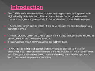
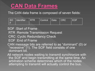
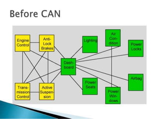
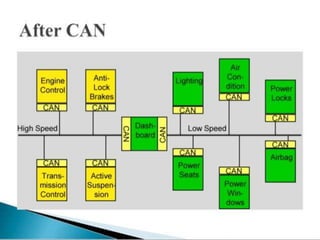
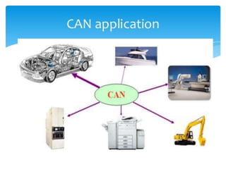
 Introduction
 CAN history
 CAN Data frames
 Arbitration
 Control and Data fields
 Before CAN
 After CAN
 Applications
 Advantages
 Limitations
 The CAN is serial communication protocol that supports real time systems with
high reliability. It detects the collisions; it also detects the errors, retransmits
corrupt messages and gives priority to the received and transmitted messages.
 The identifier length can be either 11 bits or 29 bits and the data length can vary
from 0 to 8 bytes.
 The fast growing use of the CAN protocol in the Industrial applications resulted in
development of the CAN based network.
 It is a message based communication, not address base.
 In CAN based distributed control system, the major problem is the size of
distributed area. The maximum speed of the CAN protocol is 1mbps for 50metres
and 500kbps for 100metres. Sleep mode and wakeup are available options for
each node to reduce power consumption.
 Bosch originally developed and released
CAN to address automotive network
requirements to reduce the cost and weight
of vehicle wiring harnesses . The first
release of the protocol came in 1985.
 In the 1990s CAN was standardized by ISO
11898.
The CAN data frame is composed of seven fields:
SOF :Start of Frame
RTR :Remote Transmission Request
CRC :Cyclic Redundancy Check
EOF :End of Frame
CAN message bits are referred to as “dominant” (0) or
“recessive” (1). The SOF field consists of one
dominant bit.
All network nodes waiting to transmit synchronize with
the SOF and begin transmitting at the same time. An
arbitration scheme determines which of the nodes
attempting to transmit will actually control the bus.
SO
F
Identifier RTR Control Data CRC EOF
 The arbitration field of the CAN message consists of an
11- or 29-bit identifier and a remote transmission(RTR)
bit. The CAN arbitration scheme is called “carrier sense
multiple access with collision detection”or CSMA/CD,
and assures that the highest priority message is
broadcast.
 Message priority is determined by the numerical value of
the identifier in the arbitration field, with the lowest
numerical value having the highest priority.
 Non-destructive, bit-wise arbitration resolves conflicts
among competing transmitters. This means that the bus
can be thought of as acting like an AND gate: If any
node writes a dominant (0) bit on the bus, every node
will read a dominant bit regardless of the value written
by that node.
 Every transmitting node always reads back the bus
value for each bit transmitted. If a node transmits a
recessive bit and reads back a dominant bit, it
immediately stops transmitting.
 The RTR bit simply distinguishes between data
frames and remote frames. In data frames, the RTR
bit must be dominant; in remote frames it must be
recessive.
 Arbitration is illustrated in the following Figure.
 The control field of the data frame consists of 6
bits (of which only the lower 4 are used) that
indicate the amount of data in the message.
 Since up to 8 bytes of data may be sent in one
message, the control field may take values
ranging from 000000 to 000111.
 The data to be transmitted are contained in the
data field.
 The most significant bit (MSB) of a data byte is
sent first.
 It reduces wiring since it is a distributed control and this
ensures enhancing of the system performance.
 Many CAN chip manufactures provided the data link
layer and the physical layer interfaced to the chip and all
the software developer needs to do only is to develop
the application coding.
 It provides the ability to work in different electrical
environment and ensures noise free transmission.
 Traffic congestion is eliminated as the messages are
transmitted based on their priority and it allows the
entire network to meet the timing constraints.
 It provides for error free transmission as each node can
check for errors during the transmission of the message
and send the error frame.
 Unfair access- node with a high priority can
“hog” the network.
 Poor latency for low priority nodes.
 The physical length limitation of the CAN bus
is 2km at the rate of 20kbps.
CAN is ideally suited in applications requiring
a large of short messages with high reliability
in rugged operating environments. Because
CAN is message based not address based
,it is especially well suited when data is
needed by more than one location and
system-wide data consistency is mandatory.
 https://www.elprocus.com
 SLIDESHARE: by V.Phani Krishna
 Controller Area Network (CAN): EECS 461, Fall
2008,J. A. Cook ,J. S. Freudenberg
 Vehicle Applications of Controller Area Network
:Karl Henrik Johansson , Martin T¨orngren ,
Lars Nielsen
 www.ijetae.com
Controller area network

Controller area network

  • 2.
     Introduction  CANhistory  CAN Data frames  Arbitration  Control and Data fields  Before CAN  After CAN  Applications  Advantages  Limitations
  • 3.
     The CANis serial communication protocol that supports real time systems with high reliability. It detects the collisions; it also detects the errors, retransmits corrupt messages and gives priority to the received and transmitted messages.  The identifier length can be either 11 bits or 29 bits and the data length can vary from 0 to 8 bytes.  The fast growing use of the CAN protocol in the Industrial applications resulted in development of the CAN based network.  It is a message based communication, not address base.  In CAN based distributed control system, the major problem is the size of distributed area. The maximum speed of the CAN protocol is 1mbps for 50metres and 500kbps for 100metres. Sleep mode and wakeup are available options for each node to reduce power consumption.
  • 4.
     Bosch originallydeveloped and released CAN to address automotive network requirements to reduce the cost and weight of vehicle wiring harnesses . The first release of the protocol came in 1985.  In the 1990s CAN was standardized by ISO 11898.
  • 5.
    The CAN dataframe is composed of seven fields: SOF :Start of Frame RTR :Remote Transmission Request CRC :Cyclic Redundancy Check EOF :End of Frame CAN message bits are referred to as “dominant” (0) or “recessive” (1). The SOF field consists of one dominant bit. All network nodes waiting to transmit synchronize with the SOF and begin transmitting at the same time. An arbitration scheme determines which of the nodes attempting to transmit will actually control the bus. SO F Identifier RTR Control Data CRC EOF
  • 7.
     The arbitrationfield of the CAN message consists of an 11- or 29-bit identifier and a remote transmission(RTR) bit. The CAN arbitration scheme is called “carrier sense multiple access with collision detection”or CSMA/CD, and assures that the highest priority message is broadcast.  Message priority is determined by the numerical value of the identifier in the arbitration field, with the lowest numerical value having the highest priority.  Non-destructive, bit-wise arbitration resolves conflicts among competing transmitters. This means that the bus can be thought of as acting like an AND gate: If any node writes a dominant (0) bit on the bus, every node will read a dominant bit regardless of the value written by that node.
  • 8.
     Every transmittingnode always reads back the bus value for each bit transmitted. If a node transmits a recessive bit and reads back a dominant bit, it immediately stops transmitting.  The RTR bit simply distinguishes between data frames and remote frames. In data frames, the RTR bit must be dominant; in remote frames it must be recessive.  Arbitration is illustrated in the following Figure.
  • 9.
     The controlfield of the data frame consists of 6 bits (of which only the lower 4 are used) that indicate the amount of data in the message.  Since up to 8 bytes of data may be sent in one message, the control field may take values ranging from 000000 to 000111.  The data to be transmitted are contained in the data field.  The most significant bit (MSB) of a data byte is sent first.
  • 13.
     It reduceswiring since it is a distributed control and this ensures enhancing of the system performance.  Many CAN chip manufactures provided the data link layer and the physical layer interfaced to the chip and all the software developer needs to do only is to develop the application coding.  It provides the ability to work in different electrical environment and ensures noise free transmission.  Traffic congestion is eliminated as the messages are transmitted based on their priority and it allows the entire network to meet the timing constraints.  It provides for error free transmission as each node can check for errors during the transmission of the message and send the error frame.
  • 14.
     Unfair access-node with a high priority can “hog” the network.  Poor latency for low priority nodes.  The physical length limitation of the CAN bus is 2km at the rate of 20kbps.
  • 15.
    CAN is ideallysuited in applications requiring a large of short messages with high reliability in rugged operating environments. Because CAN is message based not address based ,it is especially well suited when data is needed by more than one location and system-wide data consistency is mandatory.
  • 16.
     https://www.elprocus.com  SLIDESHARE:by V.Phani Krishna  Controller Area Network (CAN): EECS 461, Fall 2008,J. A. Cook ,J. S. Freudenberg  Vehicle Applications of Controller Area Network :Karl Henrik Johansson , Martin T¨orngren , Lars Nielsen  www.ijetae.com