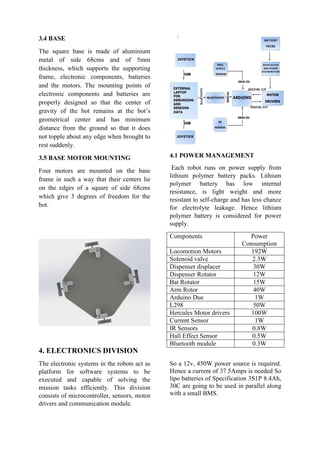
This document provides an overview of the system design and implementation of a semi-autonomous badminton playing robot. It describes the mechanical, electrical, and software systems that were developed including the robotic arm, dispenser, power management, microcontroller, sensors, motor drivers, and controls software. The overall goal was to develop an efficient robot that can compete in an annual competition by playing doubles badminton matches autonomously.
Unit IV Solved Question Bank- Robotics EngineeringSanjay Singh
This Question Bank for Robotics Engineering is only for academic purpose and not for any commercial use. Students of Anna University and other Universities can use it for reference and knowledge.
How UVC Robot disinfects Patient Room/ Operation theaters and any area that is suspected to be infected.
Also used in the food industry and Environmental services.
[EBOOK] MẪU KẾ HOẠCH DIGITAL MARKETING 2020 CHO DOANH NGHIỆPNaveeCorporation
Nội dung Ebook này được đúc kết từ nhiều nguồn thông tin chính thống và uy tín. NAVEE tin rằng nó sẽ giúp ích cho bạn trong việc xây dựng hoặc điều chỉnh các kế hoạch, giúp bạn tận dụng tốt hơn các cơ hội tuyệt vời từ Digital Marketing.
Introduction to Mechatronics – Systems – Concepts of Mechatronics approach – Need for
Mechatronics – Emerging areas of Mechatronics – Classification of Mechatronics. Sensors and
Transducers: Static and dynamic Characteristics of Sensor, Potentiometers – LVDT – Capacitance
sensors – Strain gauges – Eddy current sensor – Hall effect sensor – Temperature sensors – Light
sensors
Revolution Precrafted - NOAH19 Tel AvivNOAH Advisors
Industrial Digitisation: Company presentation by Robbie Antonio, Founder & CEO of Revolution Precrafted at the NOAH Conference 2019 in Tel Aviv, Hangar 11, 10-11 April 2019.
Project report on injection molding machineAmol Torane
This ppt contains, the working of injection molding machine, type of plastic granules used, reshaping the old plastic products into a new shape and design, the clamping mechanism used and lots more..
Autonomous Terrain Mapping Using COTS HardwareJames Anderson
Undergraduate paper submission for 2012 International Telemetering Conference
Abstract: The paper describes the development of a robotic platform which can autonomously map terrain using a COTS infrared imaging and ranging system. The robotic system is based on an omni-directional platform, and can navigate typical commercial indoor environments. An on-board processor performs surface reconstruction, and condenses the point clouds generated by the ranging system to mesh models which can be more easily stored and transmitted. The processor then correlates new frames with the existing world model by using sensor odomerty. The robot will autonomously determine the best areas of the environment to map, and gather complete three dimensional color models of arbitrary environments.
Obstacle Avoiding Robot
Robotics is a branch of science that deals with Mechanical, Electrical and Software fields. Robots are the machines that are used in our day-to-day to life to reduce men power and work accurately without any distortions. Robots can be classified into two different sections basing upon their skills as Automated and Manual. Obstacle detector is a Automated robot which itself recognizes the obstacle in its path and moves in free direction. Robot detects the obstacle by using two IR Sensors placed in front.
The IR sensors are placed on left and right side of the robot through which continuous Infrared radiation is emitted for detection of obstacles in the path. These IR Sensors are connected to a controlling element AT89c51 µc. When a obstacle is placed in the path of robot IR beam is reflected to the sensor from the obstacle. On detecting obstacle in the path sensor sends 0 volts to µc. This 0 voltage is detected by Microcontroller which avoids the obstacle by taking left or right turn. Similarly if the sensor sends +5v to Microcontroller, the Microcontroller assumes it as clear path and makes the robot to move in straight.
Two motors namely right motor and left motor are connected to Motor driver IC (L293D). L293D is interface with Microcontroller. Microcontroller sends logic 0 & logic 1 as per the programming to driver IC which makes motors to rotate in clockwise and anticlockwise direction. Wheels attached to the motors rotate accordingly with the motor shaft causing in the moment of the robot by wheels. In front portion of the robot a free wheel is attached to move the robot easily in any direction as per the requirement.
A 12Volts DC battery is attached to the circuit. As the microcontroller and sensors requires only 5v, set of resistors and capacitors are used to supply 5v DC to them. Power Management System is not maintained in the circuit as the battery can be removed after the usage of robot. So it does not cause any loss in the power of battery.
This type of robots has multiple applications in various fields. They can be used to know the strength of the opposite army in defense system. They can be used as floor and wall cleaners. They are used in automated GPS vehicles to calculate the moment of the vehicle overhead. These robots are easy to construct and cheaper in cost with long durability.
Experimental Study of Railway Track Crack Detection Using Arduino
ROBOCON 2015 Documentation
1. System Design and Implementation
of Semi-Autonomous Badminton
playing robot
G.Vamsi Krishna, K.Vamsi Krishna, N.Mithun Babu, K.Rama Krishna,
B.Sravya, Cyan Subhra Mishra, Narendra Dehury, Vikrant Sahu, Pratikshya
Panigrahi, Shri Pragnya, Vishruti Ranjan, Swati Sahoo, C.Ravi Teja, A.Sai
Anudeep, Sweta Patnaik, Prasanmit Nath, Ankit Pani, Rajat Pradhan, Anjan
Behera, Sagnik Basu, Hansa Mohapatra
2. 1. INTRODUCTION
With the introduction of robotics in the
field of sports like Badminton, Tennis the
need for advancement and modification
has grown important. Since they find
applications; from sports industry as
serving machines, sports playing machines
for practice etc., besides for observation
purposes.
Team Morpheus is a group of
multidisciplinary students studying at NIT
Rourkela in Mechanical, Electronics and
Electrical departments. The goal of our
team to develop an efficient semi-
autonomous robot that can compete at an
annual competition (ROBOCON) that is
going to be held in Pune, 2015. Two
robots are built and are expected to play
together in a badminton doubles game.
This is our second attempt in ABU-
ROBOCON hence the objective has been
to rectify our previous mistakes and to get
the basic systems of mechanical, electronic
and software tightly integrated before
advancing towards further complexities.
Based on the requirements, the team has
been divided into three division’s namely
mechanical design team, electronics and
circuit team and coding team.
2. DESIGN OVERVIEW
The design of the vehicle has been
done with utmost emphasis on
modularity, ease of control,
consistency in output and simplicity
besides the design constraints set forth
by the competition.
The four motors attached to the wheels
contribute in a 4WD that gives 3
degrees of freedom to the bot. One
motor and one pneumatic system that
is attached to the racquet and one
motor that is attached to the platform
gives 3 degrees of freedom to the
racquet. The bot can operate at a linear
velocity of 10m/s. Weighing 12kgs, the
bot measures 68cms in length, 68cms
in breadth and 70cms in height without
racquet. On board lithium polymer
batteries can sustain the vehicle
operation for at least 40 minutes. In-
house designed electronics maintains
the modularity in power management
and motion control. The software stack
has been built keeping in mind
portability, user-friendliness,
reusability and efficiency. The
debugging system is designed
efficiently for ease and accuracy.
3. MECHANICAL DIVISION
The mechanical division of the team
focuses on the design, prototyping and
manufacturing of dispenser, robotic
arm and supporting truss. The
electronics and batteries are housed in
a box with cables penetrating out to
sensors, actuators and motors. The
motors and are mounted on optimized
positions of the frame for complete
ease in movement of the bat and bot.
3. 3.1 DISPENSER
The design is focused primarily in the
areas of:
1) Ease of assembly and
disassembly.
2) Accuracy in shuttle dropping
mechanism.
3) Providing no hindrance to the
bat movement
The dispenser has a cylindrical design with
a base diameter of 115 mm and height of
76mm with 3 slots and one slot has a hole
in it for shuttle drop. The dispenser rests
on a horizontal platform which recedes
after servicing is done. This mechanism
helps in avoiding the hindrance for the
racquet.
3.2 ROBOTIC ARM
The robotic arm rests upon a DC motor
which is inclined at an angle of 40degrees
with horizontal. For the racquet control the
arm is encompassed with a motor which
controls the yaw motion and a pneumatic
which controls the pitch motion. For a
smooth and efficient movement the arm
rests upon castor wheels which can take
the load and inertia created by either
pneumatic or motor. A compressor is
mounted on other end of the bot. The
following considerations are made for
selection of the materials:
i) Light weight.
ii) Less corrosive when exposed to air.
iii) Availability and ease in machining.
3.3 STRUCTURAL ANALYSIS
Static structural analysis of the frame is
done using ANSYS CAE finite element
analysis (FEA) software package. To
withstand a load of 20N, the optimum
thickness of the member is evaluated and
the obtained results have been tested
experimentally.
The total deformation and stress values are
obtained from ANSYS CAE. Major
emphasis is laid on modularity, static and
dynamic performance besides robustness
of the frame. Aluminum L sections are
used to construct the bot’s frame as it
serves the primary purpose of strength and
in-plane alignment of all the motors. This
offers an innate flexibility in placement
and adjustment of motors positions to alter
the dynamic behavior of the vehicle.
4. 3.4 BASE
The square base is made of aluminium
metal of side 68cms and of 5mm
thickness, which supports the supporting
frame, electronic components, batteries
and the motors. The mounting points of
electronic components and batteries are
properly designed so that the center of
gravity of the bot remains at the bot’s
geometrical center and has minimum
distance from the ground so that it does
not topple about any edge when brought to
rest suddenly.
3.5 BASE MOTOR MOUNTING
Four motors are mounted on the base
frame in such a way that their centers lie
on the edges of a square of side 68cms
which give 3 degrees of freedom for the
bot.
4. ELECTRONICS DIVISION
The electronic systems in the robots act as
platform for software systems to be
executed and capable of solving the
mission tasks efficiently. This division
consists of microcontroller, sensors, motor
drivers and communication module.
4.1 POWER MANAGEMENT
Each robot runs on power supply from
lithium polymer battery packs. Lithium
polymer battery has low internal
resistance, is light weight and more
resistant to self-charge and has less chance
for electrolyte leakage. Hence lithium
polymer battery is considered for power
supply.
Components Power
Consumption
Locomotion Motors 192W
Solenoid valve 2.3W
Dispenser displacer 30W
Dispenser Rotator 12W
Bat Rotator 15W
Arm Rotor 40W
Arduino Due 1W
L298 50W
Hercules Motor drivers 100W
Current Sensor 1W
IR Sensors 0.8W
Hall Effect Sensor 0.5W
Bluetooth module 0.3W
So a 12v, 450W power source is required.
Hence a current of 37.5Amps is needed So
lipo batteries of Specification 3S1P 8.4Ah,
30C are going to be used in parallel along
with a small BMS.
5. 4.2 MICRO CONTROLLER
ARDUINO DUE
Arduino Due is a microcontroller board
based on Atmel SAM3X8E ARM Cortex-
M3 CPU. It has 54 digital input/output
pins,12 analog inputs,4 UARTs ,a 84 MHz
clock, an USB OTG capable connection, a
power jack. The primary reason for
choosing Arduino Due as it has 32-bit
ARM core that allows operations on 4
bytes wide data within a single CPU clock
when compared to other arduino boards. It
has number of facilities for communicating
with computer and other microcontrollers.
4.4 SENSORS AND ACTUATORS
Hall Effect Sensor:
A Hall Effect Sensor is a transducer that
varies its output voltage in response to
a magnetic field. Hall effect sensors of
MH 281 are used in each robot to
determine the RPM of wheels. A magnet is
mounted on wheel and a hall effect sensor
is placed at some distance away from the
wheel. During wheel rotation, the magnet
position is noted as initial position and the
Hall Effect sensor delivers output voltage
and the timer is started. It is stopped when
the magnet comes to initial position after
rotation. This time is noted and calculated
for one minute. Hence RPM of wheel is
calculated. To increase the efficiency
multiple magnets are used.
IR sensor:
A typical system for detecting infrared
radiation is given in following block
diagram
An IR sensor is used to detect obstacles in
front of robot or to differentiate between
colors depending on configuration of
sensor. The circuit required to make IR
sensor consists of two parts; the emitter
and receiver.
The emitter is simply an IR LED and the
detector is simply an IR photodiode which
is sensitive to IR light of same wavelength
as that emitted by IR LED. When IR light
falls on the photodiode, its resistance and
correspondingly, its output voltage, change in
proportion to the magnitude of the IR light
received. IR sensors are used in each robot
to make it a semi-autonomous such that
preventing the robot from getting out of
arena.
6. Motor Drivers:
A motor driver is a device that is
essentially current amplifier. The function
of which is to take a low-current control
signal and turn it into a proportionally
higher-current power source that can drive
a motor. There are two types of motor
drivers used in each robot.
Motor driver type Peak Output
Current
Hercules Motor
Driver
30A
Motor driver with
IC L298
2A
Motor Driver with IC L298:
Two motor drivers of this type are used in
each robot to drive motors of dispenser
displacer and dispenser rotator and
solenoid valve.
Hercules Motor Driver:
A total of five hercules motor drivers are
used in each robot to drive motors of
locomotion and platform.
Current Sensors:
These are Hall Effect current sensors(ACS
709) that are used by the power board to
get a feedback of current been consumed
from the batteries.
5. SOFTWARE DIVISION
Software and firmware development are
needed on different platforms. Firmware
requirements for power management,
motion controller are the major needs. For
ease of testing and quality user experience
a debugging platform is also developed.
Two joysticks are used to control two
robots. Each joystick is connected to
7. converter which sends some data values to
laptop through USB cable which are
processed in GUI made by VISUAL
STUDIO Software in embedded C.
Since the serial communication is used, a
COM PORT is created and the data
processed is sent via this COM PORT to
the Bluetooth of laptop.
When the Bluetooth of laptop is paired
with the Bluetooth of the robot connected
to Arduino Board, the data is sent to the
Bluetooth module in the robot.
The data received to the Bluetooth of robot
is automatically processed in Arduino
Board and the data thus processed in used
to control the robot.
A debug code is primarly flashed in
Arduino Board of each robot. The working
status of all the modules and actuators
used in robot are displayed in GUI using
VISUAL STUDIO Software in laptop with
this debugging code. By this we can
rectify any failure in the system.
6. CONTROLS AND STRATEGY
Two joysticks are used to operate two
robots by two operators. At certain instant
one robot is operated by two operators,
one operator for the locomotion of robot
and the other for the arm motion. This is
done so because the operation of both
locomotion and arm motion of the robot at
the same time by one operator will be
difficult.
As the game is doubles, two robots are
used. One of the robots will be played in
the front-side and the other robot in the
back-side. Some of the parts are made
autonomous.
7. APPROACH
Since the team is working on a badminton
playing robot for the first time, it
necessitated the perfection of basic
systems of each division. Till the hardware
was designed, prototyped and fabricated,
the software team started building the
framework for the same. A GUI has been
developed for interfacing a USB joystick
and acquiring data from it and take some
decisions and send appropriate commands
to the Bluetooth module (HC-05) which
will be present in the robot via the laptop’s
Bluetooth. The same GUI is also used for
debugging the bot i.e. acquiring present
battery status and working status of the
motors and other module for making the
debugging easy. Meanwhile the electronics
team has tested hall-effect sensor used for
measuring wheel RPM, used Arduino for
various purposes and a PCB has been
designed for the bot which will include all
the modules used for the bot. Meanwhile
the mechanical design team has developed
a prototype of dispenser mechanism and
the free fall of the shuttle is analyzed
thoroughly, readings were noted,
understood and it is re-designed. The
design of the dispenser was revised 2 times
and prototyped once.