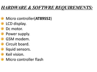
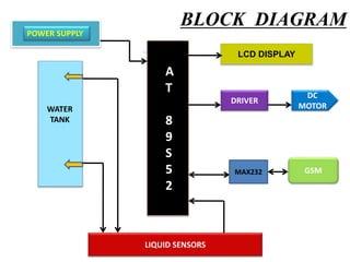
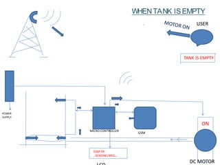
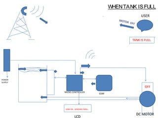
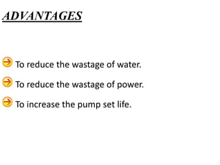
INTERNAL GUIDE
P.RAMU- Associative Professor.
M.V.PAVAN KUMAR
CONTENTS
INTRODUCTION
CURRENT SCENARIO & PROPOSED SOLUTIONS
HARDWARE AND SOFTWARE REQUIREMENTS
BLOCK DIAGRAM
FEATURES OF AT89S52 MICRO CONTROLLER
PIN CONFIGURATION
LCD ( LIQUID CRYSTAL DISPLAY)
GSM(GLOBAL SYSTEM FOR MOBILE)
MAX 232
LIQUID SENSORS
WORKING PROCEDURE
ADVANTAGES
LIMITATIONS & FUTURE SCOPE
APPLICATIONS
Generally we all know that water is more precious resource and
also there exist less amount of useful(drinking) water sources in the
nature.
So it is our reponsibility to control the wastage of water.
Inorder to over come the wastage of water we had developed a
new project i.e. “water level controller using gsm.”
In this project,the sensors will sens the water level and sends the
information to the gsm,then it sends to user.Depending upon the
received information,user may ON/OFF the motor.
INTRODUCTION
PROPOSED SOLUTIONS
The sensor will sense the water level and sends the information to
the driver of the micro controller. And the micro controller will sends
the information to the motor driver and the motor will be set to
on/off depending up on the signal .
At the same time the GSM will send the message to the user
whether the motor is on/off.
CURRENT SCENARIO
The water is wasted due to over flow.
At the same time, power is also wasted.
Micro controller(AT89S52)
LCD display.
Dc motor.
Power supply.
GSM modem.
Circuit board.
liquid sensors.
Keil vision.
Micro controller flash
HARDWARE & SOFTWRE REQUIREMENTS:
BLOCK DIAGRAM
LCD DISPLAY
DRIVER
DC
MOTOR
GSM
LIQUID SENSORS
A
T
8
9
S
5
2
POWER SUPPLY
WATER
TANK
MAX232
8K Bytes of In-System Programmable (ISP) Flash Memory
4.0V to 5.5V Operating Range
256K Internal RAM
32 Programmable I/O Lines
Three 16-bit Timer/Counters
Eight Interrupt Sources
Full Duplex UART Serial Channel
Interrupt Recovery from Power-down Mode
Watchdog Timer
Dual Data Pointer
Power-off Flag
FEATURES OF AT89S52
(A15)
(A14)
(A13)
(A12)
(A11)
(A10)
(A9)
(A8)
PIN CONFIGURATION:
RST
vccP1.0
P1.1
P1.2
P1.3
P1.4
P1.5
P1.6
P1.7
P3.0
P3.1
P3.2
P3.3
P3.4
P3.5
P3.6
P3.7
XTAL 1
XTAL 2
GND
( T2)
(T2EX)
(MOSI)
(MISO)
(SCK)
(RXD)
(TXD)
(INT0)
(INT1)
T0
T1
(WR)
(RD)
P0.0
P0.1
P0.2
P0.3
P0.4
P0.5
P0.6
P0.7
ALE/PROG
PSEN
P2.7
P2.6
P2.5
P2.4
P2.3
P2.2
P2.1
P2.0
(ADO)
(AD1)
(AD2)
(AD3)
(AD4)
(AD5)
(AD6)
(AD7)
(AD8)
A
T
8
9
S
5
2
1
2
3
4
5
6
7
8
9
10
11
12
13
14
15
16
17
18
19
20
40
39
38
37
36
35
34
33
32
31
30
29
28
27
26
25
24
23
22
21
EA
A liquid crystal display (LCD) is a thin, flat display device made up of
any number of color or monochrome pixels arrayed in front of a light
source or reflector
Common LCDs connected to the controllers sews are 16X1, 16x2 and
20x2 displays. This means 16 characters per line by 1 line 16 characters
per line by 2 lines and 20 characters per line by 2 lines, respectively
LCD (liquid crystal display)
GSM is a cellular network, which
means that mobile phones connect
to it by searching for cells in the
immediate vicinity.
GSM networks operate in four
different frequency ranges. Most
GSM networks operate in the 900
MHz or 1800 MHz bands.
It is interfaced through
TX,RX(P3.0,P3.1) of the
microcontroller .
GSM(globalsystemformobilecommunication)
It is a level shifter.
operates with single 5v
power supply.
To convert TTL logic, say
TXD,RXD pins of the
microcontroller thus need a
converter chip.
It has 4level translators,
two of which are RS232
transmitters and two of which
are RS 232 receivers.
MAX 232
It has a resistive output that varies with
the level of the fluid.
It does away with clunky mechanical
floats, and easily interfaces with electronic
control systems.
This results in a change in resistance that
corresponds to the distance from the top of
the sensor to the surface of the fluid.
The sensor's resistive output is inversely
proportional to the height of the liquid.
The lower the liquid level, the higher the
output resistance the higher the liquid level,
the lower the output resistance.
LIQUID SENSORS
WORKING PROCEDURE
USER
DC MOTOR
MICRO CONTROLLER
GSM
POWER
SUPPLY
ON
GSM OK
..SENDINGMSG…
TANK IS EMPTY
WHENTANK ISEMPTY
USER
DC MOTOR
MICRO CONTROLLER
GSM
POWER
SUPPLY
LCD
GSM OK...SENDING MSG…
TANK IS FULL
OFF
WHENTANK ISFULL
To reduce the wastage of water.
To reduce the wastage of power.
To increase the pump set life.
ADVANTAGES
LIMITATION:
It works only when the power is in ‘ON’ state.
Due to the network problems, the message send by
GSM/USER may not be send within the in time.
FUTURE SCOPE:
By using solar panels we can give power supply to the
sensor circuit and then we can monitor the water level
during power cut also.
LIMITATIONS & FUTURE SCOPE
Applicable in agricultural fields.
Applicable at reservoirs.
Applicable at oil refineries.
Applicable at water plants.
APPLICATIONS
automatic water level controlling using gsm system

automatic water level controlling using gsm system

  • 1.
    INTERNAL GUIDE P.RAMU- AssociativeProfessor. M.V.PAVAN KUMAR
  • 2.
    CONTENTS INTRODUCTION CURRENT SCENARIO &PROPOSED SOLUTIONS HARDWARE AND SOFTWARE REQUIREMENTS BLOCK DIAGRAM FEATURES OF AT89S52 MICRO CONTROLLER PIN CONFIGURATION LCD ( LIQUID CRYSTAL DISPLAY) GSM(GLOBAL SYSTEM FOR MOBILE) MAX 232 LIQUID SENSORS WORKING PROCEDURE ADVANTAGES LIMITATIONS & FUTURE SCOPE APPLICATIONS
  • 3.
    Generally we allknow that water is more precious resource and also there exist less amount of useful(drinking) water sources in the nature. So it is our reponsibility to control the wastage of water. Inorder to over come the wastage of water we had developed a new project i.e. “water level controller using gsm.” In this project,the sensors will sens the water level and sends the information to the gsm,then it sends to user.Depending upon the received information,user may ON/OFF the motor. INTRODUCTION
  • 4.
    PROPOSED SOLUTIONS The sensorwill sense the water level and sends the information to the driver of the micro controller. And the micro controller will sends the information to the motor driver and the motor will be set to on/off depending up on the signal . At the same time the GSM will send the message to the user whether the motor is on/off. CURRENT SCENARIO The water is wasted due to over flow. At the same time, power is also wasted.
  • 5.
    Micro controller(AT89S52) LCD display. Dcmotor. Power supply. GSM modem. Circuit board. liquid sensors. Keil vision. Micro controller flash HARDWARE & SOFTWRE REQUIREMENTS:
  • 6.
    BLOCK DIAGRAM LCD DISPLAY DRIVER DC MOTOR GSM LIQUIDSENSORS A T 8 9 S 5 2 POWER SUPPLY WATER TANK MAX232
  • 7.
    8K Bytes ofIn-System Programmable (ISP) Flash Memory 4.0V to 5.5V Operating Range 256K Internal RAM 32 Programmable I/O Lines Three 16-bit Timer/Counters Eight Interrupt Sources Full Duplex UART Serial Channel Interrupt Recovery from Power-down Mode Watchdog Timer Dual Data Pointer Power-off Flag FEATURES OF AT89S52
  • 8.
    (A15) (A14) (A13) (A12) (A11) (A10) (A9) (A8) PIN CONFIGURATION: RST vccP1.0 P1.1 P1.2 P1.3 P1.4 P1.5 P1.6 P1.7 P3.0 P3.1 P3.2 P3.3 P3.4 P3.5 P3.6 P3.7 XTAL 1 XTAL2 GND ( T2) (T2EX) (MOSI) (MISO) (SCK) (RXD) (TXD) (INT0) (INT1) T0 T1 (WR) (RD) P0.0 P0.1 P0.2 P0.3 P0.4 P0.5 P0.6 P0.7 ALE/PROG PSEN P2.7 P2.6 P2.5 P2.4 P2.3 P2.2 P2.1 P2.0 (ADO) (AD1) (AD2) (AD3) (AD4) (AD5) (AD6) (AD7) (AD8) A T 8 9 S 5 2 1 2 3 4 5 6 7 8 9 10 11 12 13 14 15 16 17 18 19 20 40 39 38 37 36 35 34 33 32 31 30 29 28 27 26 25 24 23 22 21 EA
  • 9.
    A liquid crystaldisplay (LCD) is a thin, flat display device made up of any number of color or monochrome pixels arrayed in front of a light source or reflector Common LCDs connected to the controllers sews are 16X1, 16x2 and 20x2 displays. This means 16 characters per line by 1 line 16 characters per line by 2 lines and 20 characters per line by 2 lines, respectively LCD (liquid crystal display)
  • 10.
    GSM is acellular network, which means that mobile phones connect to it by searching for cells in the immediate vicinity. GSM networks operate in four different frequency ranges. Most GSM networks operate in the 900 MHz or 1800 MHz bands. It is interfaced through TX,RX(P3.0,P3.1) of the microcontroller . GSM(globalsystemformobilecommunication)
  • 12.
    It is alevel shifter. operates with single 5v power supply. To convert TTL logic, say TXD,RXD pins of the microcontroller thus need a converter chip. It has 4level translators, two of which are RS232 transmitters and two of which are RS 232 receivers. MAX 232
  • 13.
    It has aresistive output that varies with the level of the fluid. It does away with clunky mechanical floats, and easily interfaces with electronic control systems. This results in a change in resistance that corresponds to the distance from the top of the sensor to the surface of the fluid. The sensor's resistive output is inversely proportional to the height of the liquid. The lower the liquid level, the higher the output resistance the higher the liquid level, the lower the output resistance. LIQUID SENSORS
  • 14.
  • 15.
    USER DC MOTOR MICRO CONTROLLER GSM POWER SUPPLY ON GSMOK ..SENDINGMSG… TANK IS EMPTY WHENTANK ISEMPTY
  • 16.
    USER DC MOTOR MICRO CONTROLLER GSM POWER SUPPLY LCD GSMOK...SENDING MSG… TANK IS FULL OFF WHENTANK ISFULL
  • 17.
    To reduce thewastage of water. To reduce the wastage of power. To increase the pump set life. ADVANTAGES
  • 18.
    LIMITATION: It works onlywhen the power is in ‘ON’ state. Due to the network problems, the message send by GSM/USER may not be send within the in time. FUTURE SCOPE: By using solar panels we can give power supply to the sensor circuit and then we can monitor the water level during power cut also. LIMITATIONS & FUTURE SCOPE
  • 19.
    Applicable in agriculturalfields. Applicable at reservoirs. Applicable at oil refineries. Applicable at water plants. APPLICATIONS