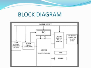
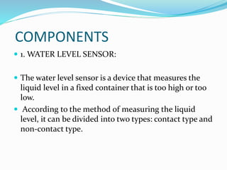
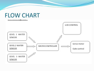
“ AUTOMATIC DAM SHUTTER
OPENING SYSTEM”
Department of Electronics And Instrumentation
Institute Of Engineering And Technology Lucknow
GUIDED BY : SUBMITTED BY:
DR. PRERNA SAUMYA RAI
( 2000520320051)
OVERVIEW
INTRODUCTION
PROBLEM
OBJECTIVE
BLOCK DIAGRAM
COMPONENTS
WORKING
FLOW CHART
CONCLUSION
INTRODUCTION
• This is an innovative system that automates the system
inside the dam. In traditional method the water level
was sensed and operated manually.
• This consumes manpower .
* It needs to be monitoired periodically .so that water
does not affect the dam walls and should not overflow
over the dam gates .
MOTIVATION
 Dam failure is one of the biggest disaster that could
happen .
 Manual dams management system cannnot be 100%
reliable .
 So there is a need of 100% automated sensor based
dam system .
 Hence the main purpose of the project is to control the
dam shutter automatically on sensing the water level .
PROBLEM
 Failure of dam is simply an uncontrolled release of
water from a reservior through dam as a result of
structural failure .
 As in the recent years dam failure has caused floods in
many cities which gave rise to many disease and many
other disaster to the human livelihood .
 So we need automation in this field to prevent such
massive disaster .
OBJECTIVE
 To reduce the load on operator .
 To decrease the cost of maitaineance on the system.
 To reduce the only use of mechanical linkages and
different mechanism in the system .
 Using this the floods and the risk of disaster can be
reduced upto certain extent .
 Therefore we need automation in this field to
maintain human liveliood .
BLOCK DIAGRAM
COMPONENTS
 1. WATER LEVEL SENSOR:
 The water level sensor is a device that measures the
liquid level in a fixed container that is too high or too
low.
 According to the method of measuring the liquid
level, it can be divided into two types: contact type and
non-contact type.
TRANSFORMER
 Transformer is the simplest device that is used to
transfer electrical energy from one alternating-current
circuit to another circuit or multiple circuits, through
the process of electromagnetic induction.
 A transformer works on the principle of
electromagnetic induction to step up or step down
voltage.
 The basic principle behind working of a transformer
is the phenomenon of mutual induction between two
windings linked by common magnetic flux.
MICROCONTROLLER
 A microcontroller is a small and low-cost
microcomputer, which is designed to perform the
specific tasks of embedded systems like displaying
microwave’s information, receiving remote signals, etc.
 The general microcontroller consists of the processor,
the memory (RAM, ROM, EPROM), Serial ports,
peripherals (timers, counters), etc.
 It is also called as a computer on a single chip.
AURDINO
 Arduino UNO is based on an ATmega328P microcontroller.
It is easy to use compared to other boards, such as the
Arduino Mega board, etc.
 The board consists of digital and analog Input/Output pins
(I/O), shields, and other circuits.
 The Arduino UNO includes 6 analog pin inputs, 14 digital
pins, a USB connector, a power jack.
 It is programmed based on IDE, which stands for
Integrated Development Environment. It can run on both
online and offline platforms.
LCD
 The term LCD stands for liquid crystal display.
 It is one kind of electronic display module used in an extensive
range of applications like various circuits & devices like mobile
phones, calculators, computers, TV sets, etc.
 These displays are mainly preferred for multi-segment light-
emitting diodes and seven segments.
 The main benefits of using this module are inexpensive; simply
programmable, animations, and there are no limitations for
displaying custom characters, special and even animations, etc.
MOTOR DRIVING RELAY CIRCUIT
 A relay is an electrically operated switch.
 The switch may have any number of contacts in
multiple contact forms, such as make contacts, break
contacts, or combination.
 Relays are used where it is necessary to control a
circuit by an independent low-power signal, or where
several circuits must be controlled by one signalations
thereof.
CONSTRUCTION
 The series of water sensors are fitted in such a way that the gate
will open partially or fully as per the requirement of water to pass
from one side to another .
 The water sensors are connected to microcontroller through
aurdino and then interfaced with lcd screen to display the level
of water .
 The transformer is connected to lcd screen through bridge
rectifiers and voltage regulator so as to convert low ac voltage to
high current and high voltage to low current .
 The microcontroller is also connected through Gate which
completes the circuit .
Working
 When the current is supplied the transformer converts it as per
requirement.
 The supply reaches to gate and microcontroller.
 When the water level touches the first sensor fixed at bottom ,
the signal is sent to microcontroller which further send the
signal to the gate and the gate opens partially.
 Now when the water touches the second sensor the gate opens
little wider .
 Same as with the topmost sensor which senses in the condition
of overflow thus the gate opens completely to aviod damage .
FLOW CHART
CONCLUSION
 The proposed way reduces the wastage of water upto
greater extent .
 Ensures efficint use of water resources for industries and
generates more precise and accurate result .
 Just one operator sufficient for closing and opening of gate
according to sensor output .
 Because of this the cost is reduced as we have used aurdino
and microcontroller instead of plc which reduces the cost .
DOC-20230916-WA0003..pptx

DOC-20230916-WA0003..pptx

  • 1.
    “ AUTOMATIC DAMSHUTTER OPENING SYSTEM” Department of Electronics And Instrumentation Institute Of Engineering And Technology Lucknow GUIDED BY : SUBMITTED BY: DR. PRERNA SAUMYA RAI ( 2000520320051)
  • 2.
  • 3.
    INTRODUCTION • This isan innovative system that automates the system inside the dam. In traditional method the water level was sensed and operated manually. • This consumes manpower . * It needs to be monitoired periodically .so that water does not affect the dam walls and should not overflow over the dam gates .
  • 4.
    MOTIVATION  Dam failureis one of the biggest disaster that could happen .  Manual dams management system cannnot be 100% reliable .  So there is a need of 100% automated sensor based dam system .  Hence the main purpose of the project is to control the dam shutter automatically on sensing the water level .
  • 5.
    PROBLEM  Failure ofdam is simply an uncontrolled release of water from a reservior through dam as a result of structural failure .  As in the recent years dam failure has caused floods in many cities which gave rise to many disease and many other disaster to the human livelihood .  So we need automation in this field to prevent such massive disaster .
  • 6.
    OBJECTIVE  To reducethe load on operator .  To decrease the cost of maitaineance on the system.  To reduce the only use of mechanical linkages and different mechanism in the system .  Using this the floods and the risk of disaster can be reduced upto certain extent .  Therefore we need automation in this field to maintain human liveliood .
  • 7.
  • 8.
    COMPONENTS  1. WATERLEVEL SENSOR:  The water level sensor is a device that measures the liquid level in a fixed container that is too high or too low.  According to the method of measuring the liquid level, it can be divided into two types: contact type and non-contact type.
  • 9.
    TRANSFORMER  Transformer isthe simplest device that is used to transfer electrical energy from one alternating-current circuit to another circuit or multiple circuits, through the process of electromagnetic induction.  A transformer works on the principle of electromagnetic induction to step up or step down voltage.  The basic principle behind working of a transformer is the phenomenon of mutual induction between two windings linked by common magnetic flux.
  • 10.
    MICROCONTROLLER  A microcontrolleris a small and low-cost microcomputer, which is designed to perform the specific tasks of embedded systems like displaying microwave’s information, receiving remote signals, etc.  The general microcontroller consists of the processor, the memory (RAM, ROM, EPROM), Serial ports, peripherals (timers, counters), etc.  It is also called as a computer on a single chip.
  • 11.
    AURDINO  Arduino UNOis based on an ATmega328P microcontroller. It is easy to use compared to other boards, such as the Arduino Mega board, etc.  The board consists of digital and analog Input/Output pins (I/O), shields, and other circuits.  The Arduino UNO includes 6 analog pin inputs, 14 digital pins, a USB connector, a power jack.  It is programmed based on IDE, which stands for Integrated Development Environment. It can run on both online and offline platforms.
  • 12.
    LCD  The termLCD stands for liquid crystal display.  It is one kind of electronic display module used in an extensive range of applications like various circuits & devices like mobile phones, calculators, computers, TV sets, etc.  These displays are mainly preferred for multi-segment light- emitting diodes and seven segments.  The main benefits of using this module are inexpensive; simply programmable, animations, and there are no limitations for displaying custom characters, special and even animations, etc.
  • 13.
    MOTOR DRIVING RELAYCIRCUIT  A relay is an electrically operated switch.  The switch may have any number of contacts in multiple contact forms, such as make contacts, break contacts, or combination.  Relays are used where it is necessary to control a circuit by an independent low-power signal, or where several circuits must be controlled by one signalations thereof.
  • 14.
    CONSTRUCTION  The seriesof water sensors are fitted in such a way that the gate will open partially or fully as per the requirement of water to pass from one side to another .  The water sensors are connected to microcontroller through aurdino and then interfaced with lcd screen to display the level of water .  The transformer is connected to lcd screen through bridge rectifiers and voltage regulator so as to convert low ac voltage to high current and high voltage to low current .  The microcontroller is also connected through Gate which completes the circuit .
  • 15.
    Working  When thecurrent is supplied the transformer converts it as per requirement.  The supply reaches to gate and microcontroller.  When the water level touches the first sensor fixed at bottom , the signal is sent to microcontroller which further send the signal to the gate and the gate opens partially.  Now when the water touches the second sensor the gate opens little wider .  Same as with the topmost sensor which senses in the condition of overflow thus the gate opens completely to aviod damage .
  • 16.
  • 17.
    CONCLUSION  The proposedway reduces the wastage of water upto greater extent .  Ensures efficint use of water resources for industries and generates more precise and accurate result .  Just one operator sufficient for closing and opening of gate according to sensor output .  Because of this the cost is reduced as we have used aurdino and microcontroller instead of plc which reduces the cost .

Editor's Notes

  • #11 A microcontroller is a small and low-cost microcomputer, which is designed to perform the specific tasks of embedded systems like displaying microwave’s information, receiving remote signals, etc.
  • #14 A relay is an electrically operated switch. It consists of a set of input terminals for a single or multiple control signals, and a set of operating contact terminals. The switch may have any number of contacts in multiple contact forms, such as make contacts, break contacts, or combinations thereof. Relays are used where it is necessary to control a circuit by an independent low-power signal, or where several circuits must be controlled by one signal. Relays were first used in long-distance telegraph circuits as signal repeaters: they refresh the signal coming in from one circuit by tra