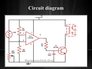
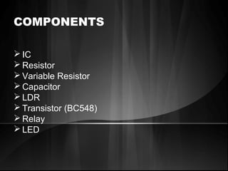
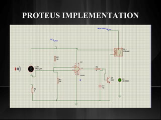
Automatic Street Light control using
LDR
GROUP MEMEBERS
M Asif UW-13-ME-BSC-052
Jawad Arshad UW-13-ME-BSC-056
Ahsan Nasim UW-13-ME-BSC-092
Circuit diagram
COMPONENTS
 IC
 Resistor
 Variable Resistor
 Capacitor
 LDR
 Transistor (BC548)
 Relay
 LED
WORKINGWORKING
• The working of circuit is very much easy to
understand. In this circuit, we used IC CA3140
which is basically an operational amplifier. Pins
2 and 3 of these IC are used to compare the
voltage and give us the output in return i.e. it
works as a potential divider in its inverting and
non-inverting inputs (pins 2 and 3).
• In this LDR and VR1 form one potential divider
which is used to provide a variable voltage at the
inverting input (that is 2) and the second potential
divider is built around non-inverting input (pin 3)
with the help of R1 and R2 which will grant half
of the supply voltage to non inverting pin.
• As we know property of LDR that during the time
of day resistance is low therefore voltage at the
inverting input ( IE pin 2) is higher than the
voltage at the non-inverting input (pin3) hence
the output at the pin6 is low so the transistor goes
into the cutoff state which means LED or bulb
will not glow.
• But in dimness or in night we know that
resistance of LDR is high hence voltage at
inverting input pin 2 of the IC CA3140
decreases than the non inverting input pin 3 as a
result output pin 6 moves to high state which
make transistor to conduct and the LED or bulb
associated to it start simmering.
PROTEUS IMPLEMENTATIONPROTEUS IMPLEMENTATION
AdvantagesAdvantages
No man power required.No man power required.
Simple Construction.Simple Construction.
Efficient method.Efficient method.
 Less Consumption of electrical energy.Less Consumption of electrical energy.
Less maintenance.Less maintenance.
Cheap and economical.Cheap and economical.
Automatic street light control system

Automatic street light control system

  • 2.
    Automatic Street Lightcontrol using LDR
  • 3.
    GROUP MEMEBERS M AsifUW-13-ME-BSC-052 Jawad Arshad UW-13-ME-BSC-056 Ahsan Nasim UW-13-ME-BSC-092
  • 4.
  • 5.
    COMPONENTS  IC  Resistor Variable Resistor  Capacitor  LDR  Transistor (BC548)  Relay  LED
  • 6.
    WORKINGWORKING • The workingof circuit is very much easy to understand. In this circuit, we used IC CA3140 which is basically an operational amplifier. Pins 2 and 3 of these IC are used to compare the voltage and give us the output in return i.e. it works as a potential divider in its inverting and non-inverting inputs (pins 2 and 3).
  • 7.
    • In thisLDR and VR1 form one potential divider which is used to provide a variable voltage at the inverting input (that is 2) and the second potential divider is built around non-inverting input (pin 3) with the help of R1 and R2 which will grant half of the supply voltage to non inverting pin. • As we know property of LDR that during the time of day resistance is low therefore voltage at the inverting input ( IE pin 2) is higher than the voltage at the non-inverting input (pin3) hence the output at the pin6 is low so the transistor goes into the cutoff state which means LED or bulb will not glow.
  • 8.
    • But indimness or in night we know that resistance of LDR is high hence voltage at inverting input pin 2 of the IC CA3140 decreases than the non inverting input pin 3 as a result output pin 6 moves to high state which make transistor to conduct and the LED or bulb associated to it start simmering.
  • 9.
  • 10.
    AdvantagesAdvantages No man powerrequired.No man power required. Simple Construction.Simple Construction. Efficient method.Efficient method.  Less Consumption of electrical energy.Less Consumption of electrical energy. Less maintenance.Less maintenance. Cheap and economical.Cheap and economical.