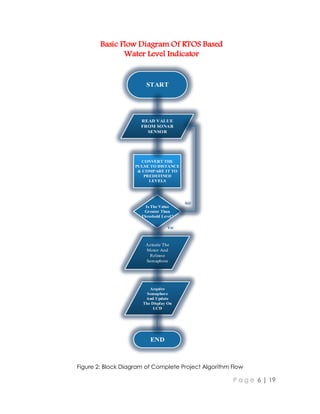
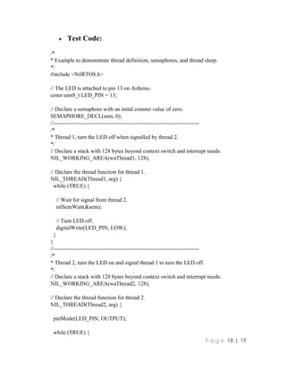
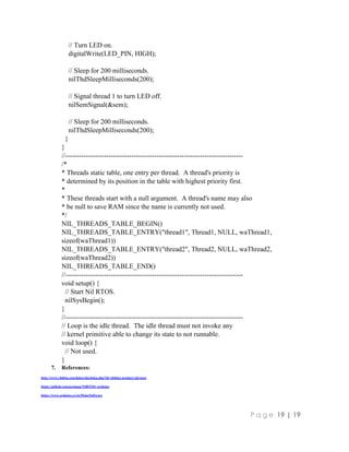
This document describes a project to monitor and control water level in a tank using an ultrasonic sensor and Arduino with a real-time operating system. It uses an ultrasonic sensor to constantly monitor water level and a pump to fill the tank when needed. The system is modeled as 4 tasks - one to read sensor data, one to control the pump, one to update an LCD display, and an idle task. The tasks communicate using semaphores to synchronize access to shared resources.
The paper presents an Arduino-based wireless sensor network to monitor parking lots using a non-standard low-power energy-balanced system. The event-driven routing protocol follows the hierarchical clustering philosophy. Energy is saved by minimising the number of transmissions needed to forward information to the base station. The smart sensor platform is build using the popular Arduino development platform, Sharp IR distance sensors and nRF24 low-power radio modules. Our practical results show that this platform is easy to use, but not the most appropriate platform to develop low-power wireless sensor network applications.
Webinar: Practical DDR Testing for Compliance, Validation and Debugteledynelecroy
Join Teledyne LeCroy for this free webinar as we first cover the basics of a DDR interface with a focus on physical-layer test challenges and solutions to common problems. We will then outline the general procedures and considerations for compliance, debug and validation test scenarios. Finally, case studies will illustrate how to apply sophisticated test tools to solve real-life problems.
Essential principles of jitter part 2 the components of jitterteledynelecroy
-The power of statistical analysis
-The five fundamental types of jitter: ISI, DCD, Periodic, Random, Other
-Their statistical “signature”
-The jitter “tree”
-Synthesizing examples based on their root cause
PAM4 Analysis and Measurement Considerations WebinarHilary Lustig
This webinar explores the acquisition and analysis of PAM4 waveforms. We will show PAM4 Test Configurations, Compliance Measurements and Debug Techniques.
Webinar Slides: Probing Techniques and Tradeoffs – What to Use and Whyteledynelecroy
Engineers must commonly probe low and high frequency signals with high signal fidelity. Typical passive probes with high input impedance and capacitance provide good response at lower frequencies, but inappropriately load the circuit and distort signals at higher frequencies.
Join Teledyne LeCroy for this webinar as we discuss:
- Selecting the right probing techniques to maximize the accuracy of your measurements
- Probe specifications and their implications on the measured signal
- Variety of probes and accessories available for measurement
- Virtual probing software tools that allow the user to probe the signal when direct access is physically impossible
This session combines the high speed analog signal chain from RF to baseband with FPGA-based digital signal processing for wireless communications. Topics include the high speed analog signal chain, direct conversion radio architecture, the high speed data converter interface, and FPGA-based digital signal processing for software-defined radio. The demo board uses the latest generation of Analog Devices’ high speed data converters, RF, and clocking devices, along with the Xilinx Zynq-7000 SoC. Other topics of discussion include the imperfections introduced by the modulator/demodulator with particular focus on the effect of temperature and frequency changes. In-factory and in-field algorithms that reduce the effect of these imperfections, with particular emphasis on the efficacy of in-factory set-and-forget algorithms, are examined.
Essentials of jitter part 3 webinar slidesteledynelecroy
In this final part, we will explore how we measure and analyze jitter in high speed serial links.
We will look at how to take a measurement on less than a million bits and extrapolate the total jitter to a million times as many bits and when we need to find the root cause of jitter, how to decompose the total jitter into its five components.
USB 3.1 Gen 2 Compliance Testing and Debug Webinarteledynelecroy
Join Teledyne LeCroy for this free webinar as we analyze the major changes in the standard compared to its previous versions and offer solutions for compliance testing and debug to help in analysis and characterization of USB 3.1 Gen 2 signals and interfaces.
The USB 2.0 standard is widely deployed in both computer and embedded systems. Compliance testing for this standard includes signal integrity as well as a number of low-level protocol tests.
This presentation provides an overview of the test requirements for USB 2.0 compliance and provide background on each test case. Details of fixtures and signal integrity requirements are highlighted in detail.
For more information visit http://rohde-schwarz-scopes.com or call (888) 837-8772 to speak to a local Rohde & Schwarz expert.
Jitter measurements are commonly done taking small snapshots in time, yet systems often experience jitter from sources that occur over relatively long time intervals, which may not be accounted for using short time interval measurements methods.
In this webinar we will present the application of a real time, digital clock recovery and trigger system to the measurement of jitter on clock and data signals. Details of the measurement methodology will be provided along with measurement examples on both clock and data signals.
You Will Learn:
- What is Jitter
- Different types of Jitter
- Jitter measurement techniques
- Benefits of Jitter analysis using real-time DDC techniques
Nov 12 Webcast: Eliminate Pitfalls of DDR Memory Testing
Join Teledyne LeCroy's, Mike Hertz, for this free webinar on using an oscilloscope for validation and debug of DDR2/3/4 physical layer measurements.
Topics covered will include: probing, connectivity, recommended device patterns, de-embedding, examples of good and bad waveforms, and debugging steps and techniques.
Mike Hertz has been a Field Applications Engineer with Teledyne LeCroy in Michigan for 14 years.
Small, widely available and dirt-cheap ultrasonic sensors enable us to design both simple and lavish measuring devices for all kinds of ranging. Take one of these modules, add a display, a couple of press-buttons and a micro-controller loaded with software, and you now have all the ingredients for a circuit of this kind.
Automatic water level monitoring and control system using IoTDanish Mehraj
This is the documentation for making Automatic water level monitoring and control system using Internet of Thimgs (IoT) which will help is to save water and removes the efforts to take care of watering u[ the tanks in homes and offices.
Traffic density dependent taffic light controller pdf NAVODITA KUMARI
By using this system configuration we can reduce the possibilities of traffic jams caused by traffic lights to an extent. The number of passing vehicles on the road decides the density range of traffics and on the basis of vehicle count microcontroller decides the traffic light delays.
Ijeee 33-36-surveillance system for coal mines based on wireless sensor networkKumar Goud
Abstract: The foremost critical task for coal mine is of keeping track of miners spread out across a large mining areas .It becomes even difficult when mine tunnels collapse. Many mines use a radio system to track miners, but when a collapse occurs, the base stations connected by a thin wire often are rendered useless. In this project to overcome the demerits of radio system we used wireless technology for tracking the miners. For this purpose a small RF transmitter module is equipped to each person entering a mine. Each transceiver placed in the mine look after the location of miners. The transceivers communicate with base stations through Zigbee module. In addition of tracking the location of miners we also include sensors such as temperature & humidity to intimate the base station & miners when some atmosphere changes occur. Mine operators are now able to monitor the real-time locations of each miner to better pinpoint their locations in the event of an emergency. Even after a full-day of use, mine operators can locate an individual miner within ten feet.
Key Words: Wireless sensor networks (WSN), ZIGBEE, and LPC2148.
Analysis and Construction of a Robot controlled by a Universal Remote ControlIJERD Editor
This paper aims at controlling a robot that is a tank like vehicle using a universal infrared remote
control. The infrared signal sent from the universal infrared remote control is received by IR receiver and
decoded by the microcontroller PIC16F873A using an algorithm embedded in the microcontroller. The output
from the microcontroller is fed to the motor driver which drives the left and right motors. The robot‟s motor
control can be speed controlled by using PWM/PDM (Pulse Width Modulation/ Pulse Duration Modulation)
technique
Automation in agriculture field using arm 7 based roboteSAT Journals
Abstract This paper is about the smart agriculture robot which superimposed the all types of huddles in farming issues, for which the web of several adverse system are interfaced, the most important issue of the farming are water resource management, conservation and watering on the plant in the appropriate manner with exact quantity. In which the second obstacle strikes is the exact quantity and proportion. which is going to be detected by the soil moisture sensor. The water sprinkling is done by the robot on the response of moisture reading, using water sprinkler. The sensitivity curve of moisture sensor is drafted by analysis of the soil moisture sensor is shown, simulation result of system along with the circuit diagram are presented, working algorithm is also explained which is designed such as to work simultaneously in association with the system.. Keywords- farming water resourcemen; soil moisture sensor; water sprinkler; AVR ATMEGA 8; ARM LPC2138
• As now a days railway accidents are occuring more and more, large amount of people lost their lives, and economical impact of it is also very high. This all happens due to improper management, and less control available!!
Due to this project lot of information gets gather about train, and so it will help for BETTER MANAGEMENT.
• Due to this, human labor can be minimized, so government can plant this labor at other work and it can improve other system also.
• By automatic signals, accidents of train on same track will get minimized so health of people traveling through train gets highly ensured.
Its about over head water management system, to control the over flow of water on the over head water tank, reduce the manpower power and it can automate the motors, wireless . if any one interest to for there development the project, please feel free no contact me.
Floor cleaning robot(autonomus mannual) vatsal shah-ec_4th year
ESD_Project-Report
1. P a g e 0 | 19
Project Report
Submitted By:
Ahmad Faizan
Humayun Akhtar
Submitted To:
Dr. Shahzad Ahmad Butt
2. P a g e 1 | 19
1. INTRODUCTION:
This is simple water level controller but the new thing we’ll be using is modeling this
application in a real time embedded system using RTOS (Real Time Operating System).
What this Embedded system will do is plain simple. It will constantly monitor the level of
our water tank using an “Ultrasonic Sound Sensor” (SONAR) and check the level of
water using the reelection of sound it receives back generated from the speaker.
After that it will check if the water Tank is full or not according to the readings it received
from the sensor. If the level of water is not at the specified position. It will simply actuate
the water pump using “Arduino’s ATmega328P” until it is reached to the “full” level.
All of the status is being shown on “16x2 LCD display” which will display information
like current motor status, water tank level percentage. ]
Why SONAR sensor?
We have two methods for sensing water level
a) Contact methods are resistive method, capacitive and inductive methods
(magnetostriction).
b) Contactless methods are optical method, radar and ultrasonic method. Because we
didn’t want to affect the quality of water in tank we implement one of the
contactless methods i-e ultrasonic sensor
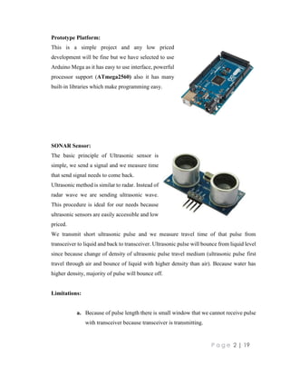
2. Equipment:
a. Arduino Mega w/(AT mega 2560)
b. SONAR sensor HC SR04
c. 16x2 characters Alphanumeric LCD
d. Ethernet cables for extension
e. Water Tank
f. Battery Pack 5v/Charger
3. P a g e 2 | 19
Prototype Platform:
This is a simple project and any low priced
development will be fine but we have selected to use
Arduino Mega as it has easy to use interface, powerful
processor support (ATmega2560) also it has many
built-in libraries which make programming easy.
SONAR Sensor:
The basic principle of Ultrasonic sensor is
simple, we send a signal and we measure time
that send signal needs to come back.
Ultrasonic method is similar to radar. Instead of
radar wave we are sending ultrasonic wave.
This procedure is ideal for our needs because
ultrasonic sensors are easily accessible and low
priced.
We transmit short ultrasonic pulse and we measure travel time of that pulse from
transceiver to liquid and back to transceiver. Ultrasonic pulse will bounce from liquid level
since because change of density of ultrasonic pulse travel medium (ultrasonic pulse first
travel through air and bounce of liquid with higher density than air). Because water has
higher density, majority of pulse will bounce off.
Limitations:
a. Because of pulse length there is small window that we cannot receive pulse
with transceiver because transceiver is transmitting.
4. P a g e 3 | 19
Solution: This problem is simple to solve: we placed our sensor higher from
maximum water level for few centimeters allowing receiver to start
receiving.
b. Because of the beam width we are limited with tank diameter. If tank
diameter is too small, signal could bounce of tank’s walls and could cause
false readings.
Solution:
By using a tank whose diameter is reasonably large we can avoid this
problem
3. RTOS (Real-Time Operating System):
There are many compatible RTOS’s for Atmel’s AVR microprocessors like FreeRTOS,
RTuinOS, ChibiOS/RT, etc. But I have chosen ChibiOS as it is free to use under GPL
license. ChibiOS/Nil is designed for embedded applications on 8, 16 and 32 bit
microcontrollers; size and execution efficiency are the main project goals. It’s very easy to
use and scalable as compared to FreeRTOS.
ChibiOS/Nil Features:
NIL has been created with the idea to bring RTOS functionalities to very small devices and
yet to be a full-fledged RTOS.
In Brief
Tiny RTOS, below 1kB of code space in its maximum configuration.
Small size of memory objects like Thread, Semaphores etc.
Focus on memory size, the target is to keep it below 1kB in its maximum
configuration. Common objects must take the minimal amount of RAM.
Scalable from 8 bits architectures upward.
Upward compatible with RT.
Reasonable API. Common features must be supported, it has to be an usable
RTOS not just minimal.
Fully Static Architecture.
Static tasks table, all tasks are declared statically.
Clean and elegant code base.
5. P a g e 4 | 19
Predictable and Deterministic.
Fully compliant with HAL OSAL.
MISRA 2012 compliance.
Fully static architecture.
4. Detailed Algorithm Explained:
Basically we’ll model this real time problem into 4
tasks as following:
a) Task 1:
In Thread 1 we’re configuring Sonar sensor for
measuring distances and once the Distance is measure
then it will compare it will hardcoded values for
different levels of water if it detect tank is not full it will signal a Binary Semaphore using
Wait and Signal Synchronization. Otherwise it will only signal it for LCD display without
changing output of motor.
1. First we Configure Sonar sensor Trigger and Echo pins on our uC.
2. Next in a while loop configuration and measuring the distance method starts.
3. Trig pin is set to high for 10 microseconds.
4. Pulse in function is used.
5. Pulse in function give us the duration from when the function called and specific
value being set on the pin we pass through the function.
6. Distance is measure in centimeters according to the formula given in Datasheet
7. On the value of distance decision is made if the distance is equal to 7cm or less
then 7cm then the Water pump is turned on.
8. If the distance is has increased to a certain threshold then the Motor is turned on
to fill the Tank.
ChibiOs/Nil
6. P a g e 5 | 19
Figure 1: Figure showing How Ultrasonic Waves propagate and reflect back after hitting
any object in its path
b) Task 2:
Basic Purpose of this Task is to show the Led Status and Turn on the Realy if the
Semaphore is available released in second task if the certain distance thresholds are met.
1. It first set out pin mods.
2. Then if the Semaphore is available it simply acquires it and turn on the Relay which
drives the motor and Status Led’s.
3. After that it release semaphore for Display to show the status of Water Tank in cm.
c) Task 3:
Basic Purpose of this task is to control the Display mechanism it will show distance in
cm.It will try the semaphore and check if it is available or not, if it’s available then it will
acquire it and show the level of water tank by displaying it on LCD display
7. P a g e 6 | 19
START
READ VALUE
FROM SONAR
SENSOR
CONVERT THE
PULSE TO DISTANCE
& COMPARE IT TO
PREDEFINED
LEVELS
Is The Value
Greater Than
Threshold Level?
Actuate The
Motor And
Release
Semaphore
Acquire
Semaphore
And Update
The Display On
LCD
END
NO
Yes
Basic Flow Diagram Of RTOS Based
Water Level Indicator
Figure 2: Block Diagram of Complete Project Algorithm Flow
9. P a g e 8 | 19
5. Hardware implementation:
6. Arduino Code:
#include <avr_heap.h>
#include <nil.h>
#include <nilconf.h>
#include <nilcore.h>
#include <NilFIFO.h>
#include <NilRTOS.h>
#include <NilSerial.h>
#include <niltypes.h>
#include <LiquidCrystal.h>
10. P a g e 9 | 19
/*
* Example to demonstrate thread definition, semaphores, and thread sleep.
*/
// Declare a semaphore with an inital counter value of zero.
SEMAPHORE_DECL(semOn, 0);
//SEMAPHORE_DECL(semOff, 0);
SEMAPHORE_DECL(semDisplay, 0);
//------------------------------------------------------------------------------
/*
HC-SR04 Ping distance sensor:
VCC to arduino 5v
GND to arduino GND
Echo to Arduino pin 9
Trig to Arduino pin 8*/
#define echopin 9 // echo pin
#define trigpin 8 // Trigger pin
LiquidCrystal lcd1(12,10, 5, 4, 3, 2);
11. P a g e 10 | 19
long duration, distance;
//------------------------------------------------------------------------------
/*
* Thread 1, turn the LED off when signalled by thread 2.
*/
// Declare a stack with 128 bytes beyond context switch and interrupt needs.
NIL_WORKING_AREA(waThread1, 128);
int change=0;
int newd=0;
// Declare the thread function for thread 1.
NIL_THREAD(Thread1, arg) {
pinMode (trigpin, OUTPUT);
pinMode (echopin, INPUT );
while (TRUE) {
digitalWrite(trigpin,LOW);
delayMicroseconds(2);
digitalWrite(trigpin,HIGH);
delayMicroseconds(10);
duration=pulseIn (echopin,HIGH);
distance= duration/58.2;
12. P a g e 11 | 19
distance+=1;
if (distance >= 12 )
{
if(newd-distance<=1)
{
nilSemSignal(&semOn);//signal semaphore to turn the relay on
}
}
else if (distance <=7)
{
digitalWrite (53,LOW);
digitalWrite (51,LOW);
if(newd-distance<=1)
{
nilSemSignal(&semDisplay);
}
}
nilThdSleepMilliseconds(50);
newd=distance;
}
}
//------------------------------------------------------------------------------
/*
* Thread 2, turn the LED on and signal thread 1 to turn the LED off.
*/
13. P a g e 12 | 19
// Declare a stack with 128 bytes beyond context switch and interrupt needs.
NIL_WORKING_AREA(waThread2, 128);
// Declare the thread function for thread 2.
NIL_THREAD(Thread2, arg) {
pinMode (53, OUTPUT);//relay
pinMode (51,OUTPUT);//led status
while (TRUE) {
//nilThdSleepMilliseconds(50);
nilSemWait(&semOn);
digitalWrite (53,HIGH);
digitalWrite (51,HIGH);
nilSemReset(&semOn,0);
nilSemSignal(&semDisplay);
}
}
//------------------------------------------------------------------------------
//Thread 3,
// Declare a stack with 128 bytes beyond context switch and interrupt needs.
NIL_WORKING_AREA(waThread3, 128);
// Declare the thread function for thread 2.
long count=0;
NIL_THREAD(Thread3, arg) {
while (TRUE) {
14. P a g e 13 | 19
//nilThdSleepMilliseconds(50);
// if(nilSemGetCounterI(&semDisplay)==1)
//{
//lcd1.clear();
nilSemWait(&semDisplay);
count=0;
lcd1.setCursor(0,0);
lcd1.print("---*********---");
lcd1.setCursor(0,1);
lcd1.print("Distance: ");
lcd1.print(distance);
//lcd1.setCursor(14,1);
lcd1.print(" cm");
/*if(millis()-count>1000)
{
lcd1.clear();
count=millis();
}
nilSemReset(&semDisplay,0);*/
nilThdSleepMilliseconds(200);
lcd1.clear();
//}
}
}
//------------------------------------------------------------------------------
/*
15. P a g e 14 | 19
* Threads static table, one entry per thread. A thread's priority is
* determined by its position in the table with highest priority first.
*
* These threads start with a null argument. A thread's name may also
* be null to save RAM since the name is currently not used.
*/
NIL_THREADS_TABLE_BEGIN()
NIL_THREADS_TABLE_ENTRY("thread2", Thread2, NULL, waThread2, sizeof(waThread2))//Relay
on-off
NIL_THREADS_TABLE_ENTRY("thread1", Thread1, NULL, waThread1, sizeof(waThread1))//read
sonar
NIL_THREADS_TABLE_ENTRY("thread3", Thread3, NULL, waThread3, sizeof(waThread3))//lcd1
display
NIL_THREADS_TABLE_END()
//------------------------------------------------------------------------------
void setup() {
//-------
lcd1.begin(16,2);
lcd1.clear();
lcd1.setCursor(0,0);
lcd1.print("RTOS based Water Level Indicator...");
lcd1.setCursor(0,1);
lcd1.print(" Ahmad Faizan :)");
for (int positionCounter = 0; positionCounter <20; positionCounter++) {
// scroll one position left:
lcd1.scrollDisplayLeft();
// wait a bit:
delay(150);
16. P a g e 15 | 19
}
// scroll 29 positions (string length + display length) to the right
// to move it offscreen right:
for (int positionCounter = 0; positionCounter < 22; positionCounter++) {
// scroll one position right:
lcd1.scrollDisplayRight();
// wait a bit:
delay(150);
}
lcd1.clear();
//---------------
// Start Nil RTOS.
nilSysBegin();
}
//------------------------------------------------------------------------------
// Loop is the idle thread. The idle thread must not invoke any
// kernel primitive able to change its state to not runnable.
void loop() {
// Not used.
}
7. PORTING NilRTOS on Arduino
17. P a g e 16 | 19
Guide for porting NilRTOS:
1. Download NilRTOS (library version) from the following link:
https://github.com/greiman/NilRTOS-Arduino
2. After that extract the zip file named as NilRTOS-Arduino-master.zip and double click
on library.
3. Copy all the files in it.
4. Paste in the library path of your Arduino IDE in the following path:
C:Program Files (x86)Arduinolibraries
18. P a g e 17 | 19
5. Now open up your Arduino IDE, select Sketch =>Include Library=>NilRTOS
Click on NilRTOS library.
6. Congratulation! You just ported NilRTOS on your Arduino IDE.
For API documentation, double click on NilRTOS.html found in NilRTOS-Arduino-
master.zip file.
19. P a g e 18 | 19
Test Code:
/*
* Example to demonstrate thread definition, semaphores, and thread sleep.
*/
#include <NilRTOS.h>
// The LED is attached to pin 13 on Arduino.
const uint8_t LED_PIN = 13;
// Declare a semaphore with an inital counter value of zero.
SEMAPHORE_DECL(sem, 0);
//------------------------------------------------------------------------------
/*
* Thread 1, turn the LED off when signalled by thread 2.
*/
// Declare a stack with 128 bytes beyond context switch and interrupt needs.
NIL_WORKING_AREA(waThread1, 128);
// Declare the thread function for thread 1.
NIL_THREAD(Thread1, arg) {
while (TRUE) {
// Wait for signal from thread 2.
nilSemWait(&sem);
// Turn LED off.
digitalWrite(LED_PIN, LOW);
}
}
//------------------------------------------------------------------------------
/*
* Thread 2, turn the LED on and signal thread 1 to turn the LED off.
*/
// Declare a stack with 128 bytes beyond context switch and interrupt needs.
NIL_WORKING_AREA(waThread2, 128);
// Declare the thread function for thread 2.
NIL_THREAD(Thread2, arg) {
pinMode(LED_PIN, OUTPUT);
while (TRUE) {
20. P a g e 19 | 19
// Turn LED on.
digitalWrite(LED_PIN, HIGH);
// Sleep for 200 milliseconds.
nilThdSleepMilliseconds(200);
// Signal thread 1 to turn LED off.
nilSemSignal(&sem);
// Sleep for 200 milliseconds.
nilThdSleepMilliseconds(200);
}
}
//------------------------------------------------------------------------------
/*
* Threads static table, one entry per thread. A thread's priority is
* determined by its position in the table with highest priority first.
*
* These threads start with a null argument. A thread's name may also
* be null to save RAM since the name is currently not used.
*/
NIL_THREADS_TABLE_BEGIN()
NIL_THREADS_TABLE_ENTRY("thread1", Thread1, NULL, waThread1,
sizeof(waThread1))
NIL_THREADS_TABLE_ENTRY("thread2", Thread2, NULL, waThread2,
sizeof(waThread2))
NIL_THREADS_TABLE_END()
//------------------------------------------------------------------------------
void setup() {
// Start Nil RTOS.
nilSysBegin();
}
//------------------------------------------------------------------------------
// Loop is the idle thread. The idle thread must not invoke any
// kernel primitive able to change its state to not runnable.
void loop() {
// Not used.
}
7. References:
http://www.chibios.org/dokuwiki/doku.php?id=chibios:product:nil:start
https://github.com/greiman/NilRTOS-Arduino
https://www.arduino.cc/en/Main/Software