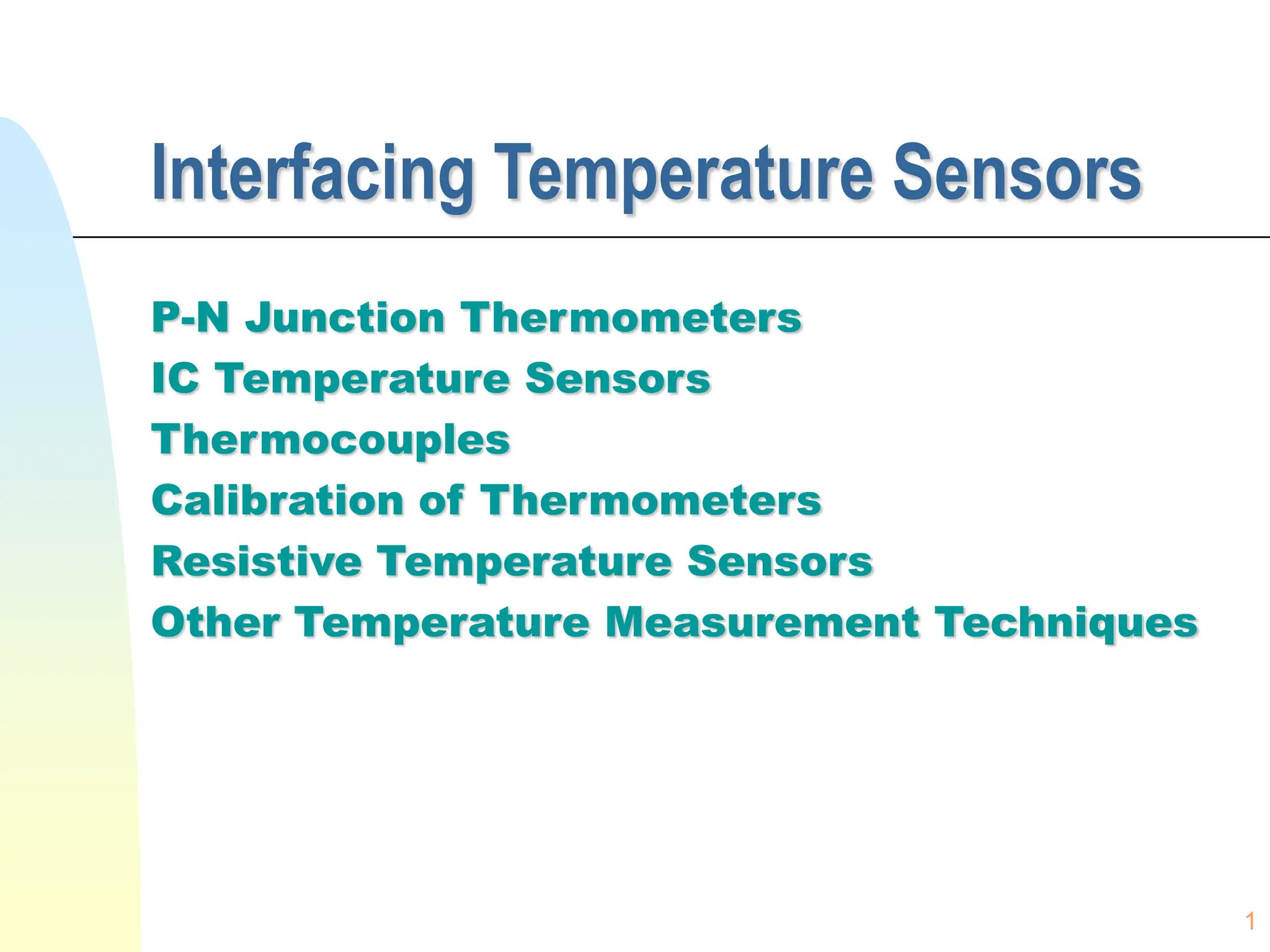
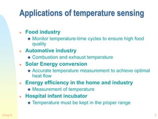
This document discusses various temperature sensing techniques including P-N junction thermometers, IC temperature sensors, thermocouples, and resistive temperature sensors. It provides details on the principles and applications of different types of temperature sensors like diode thermometers, transistor thermometers, IC sensors like LM135 and AD590, thermocouples, platinum resistance thermometers, and thermistors. The document also covers topics like calibration of thermometers, interfacing temperature sensors, and conversion of thermal voltage to temperature.
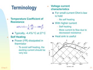
![Chap 0 4
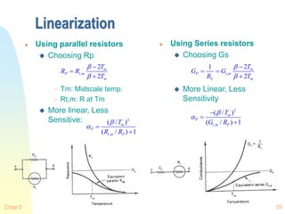
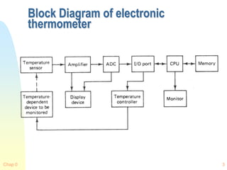
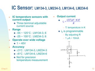
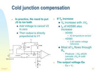
P-N Junction Thermometers
Principle of Diode
Thermometer
Forward Biased Current
Voltage
Where T is in K
Voltage vs. Temperature
Useful range
40 ~ 400K
[exp( ) 1]
2
s
qV
I I
kT
4.6
(ln ln )
g
E kT
V M I
q q
](https://image.slidesharecdn.com/7temperaturesensor-240302135949-70e3e6b9/85/7_Temperature_Sensor-ppt_ajinkya_xxxxxxxx-4-320.jpg)
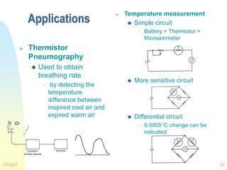
![Chap 0 5
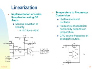
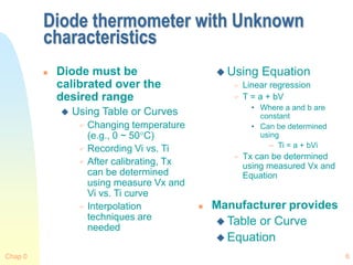
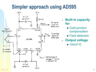
Diode thermometer with known
characteristics
Motorola MTS 105
Calibrate Diode to obtain
accurate output
Constant Current source
must be very stable
1C accuracy
0.002K with precision
GaAs Diode
Calibration Procedures
Determine VBE at
extremes (-40C and
150C)
Plot line using VBE(-40C) and
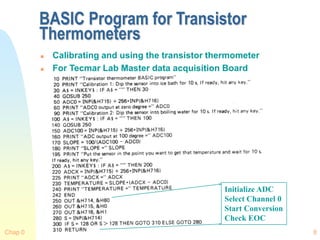
VBE(150C)
Given VBE(Tx), Tx can be found
using curve from step 2 or
equation
Diode are more sensitive and
linear than others
Wide range
Less repeatable
Affected by Magnetic (>
2.25 0.003( 600) /
c BE
T V mV C
[ ( ) (25 )]/ 25
x BE x BE c
T V T V C T
](https://image.slidesharecdn.com/7temperaturesensor-240302135949-70e3e6b9/85/7_Temperature_Sensor-ppt_ajinkya_xxxxxxxx-5-320.jpg)
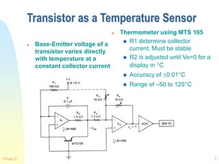
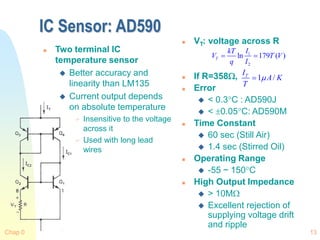
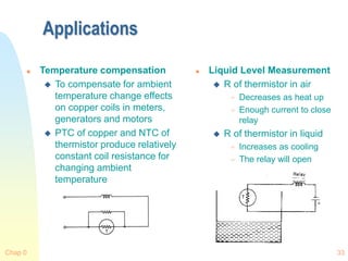
![Chap 0 26
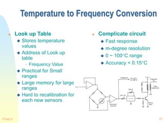
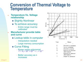
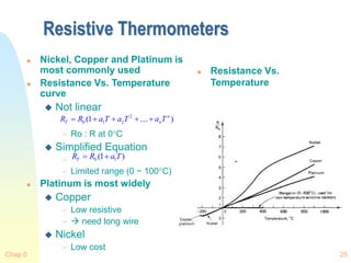
Platinum Thermometers
SPRT
Standard Platinum
Resistance
Thermometer
Range
13.81K ~ 903.89K
Some are designed to
1050C
Callendar-Van Dusen
Equation
-183 ~ 630C Range
Typically
0
3
[ (0.01 1)(0.01 )
(0.01 1)(0.01 ) ]
T
R R T T T
T T
1
0
0.00392
1.49
0( 0),0.11( 0)
100
C
T T
R
](https://image.slidesharecdn.com/7temperaturesensor-240302135949-70e3e6b9/85/7_Temperature_Sensor-ppt_ajinkya_xxxxxxxx-26-320.jpg)
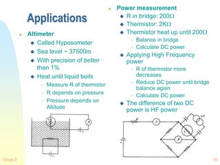
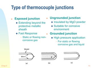
![Chap 0 30
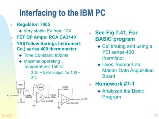
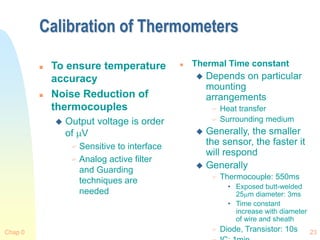
Empirical Correction
Basic Characteristics
Where
Ro : R at known To
• Usually 298.15K
: Material constant for
thermistor in K
• Determined from R
obtained at 0 and 50C
• 1500 ~ 6000K range
– Typically, 4000K
Few ~ 10M range
Steinhart-Hart Equation
Where
A, B, C are found by
solving three equations
with known R and T
Accuracy < 0.01C
More narrow range
-40C < T1, T2, T3 <150C,
|T2-T1|<50C, |T3-T2|<50C
0
0
1 1
exp[ ( )]
T
R R
T T
3
1
ln (ln )
A B R C R
T
1
ln
B
C
T R A
](https://image.slidesharecdn.com/7temperaturesensor-240302135949-70e3e6b9/85/7_Temperature_Sensor-ppt_ajinkya_xxxxxxxx-30-320.jpg)