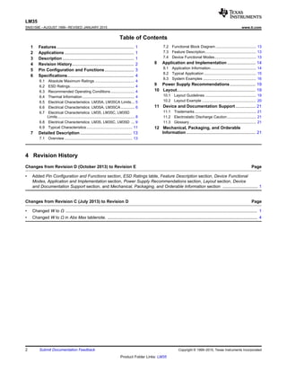
LM35
+VS
R1
VOUT
JVS
LM35
+VS
(4 V to 20 V)
OUTPUT
0 mV + 10.0 mV/°C
Product
Folder
Sample &
Buy
Technical
Documents
Tools &
Software
Support &
Community
LM35
SNIS159E –AUGUST 1999–REVISED JANUARY 2015
LM35 Precision Centigrade Temperature Sensors
1 Features 3 Description
The LM35 series are precision integrated-circuit1• Calibrated Directly in Celsius (Centigrade)
temperature devices with an output voltage linearly-
• Linear + 10-mV/°C Scale Factor proportional to the Centigrade temperature. The
• 0.5°C Ensured Accuracy (at 25°C) LM35 device has an advantage over linear
temperature sensors calibrated in Kelvin, as the user• Rated for Full −55°C to 150°C Range
is not required to subtract a large constant voltage• Suitable for Remote Applications
from the output to obtain convenient Centigrade
• Low-Cost Due to Wafer-Level Trimming scaling. The LM35 device does not require any
external calibration or trimming to provide typical• Operates from 4 V to 30 V
accuracies of ±¼°C at room temperature and ±¾°C• Less than 60-μA Current Drain
over a full −55°C to 150°C temperature range. Lower
• Low Self-Heating, 0.08°C in Still Air cost is assured by trimming and calibration at the
• Non-Linearity Only ±¼°C Typical wafer level. The low-output impedance, linear output,
and precise inherent calibration of the LM35 device• Low-Impedance Output, 0.1 Ω for 1-mA Load
makes interfacing to readout or control circuitry
especially easy. The device is used with single power2 Applications
supplies, or with plus and minus supplies. As the
• Power Supplies LM35 device draws only 60 μA from the supply, it has
very low self-heating of less than 0.1°C in still air. The• Battery Management
LM35 device is rated to operate over a −55°C to• HVAC
150°C temperature range, while the LM35C device is
• Appliances rated for a −40°C to 110°C range (−10° with
improved accuracy). The LM35-series devices are
available packaged in hermetic TO transistor
packages, while the LM35C, LM35CA, and LM35D
devices are available in the plastic TO-92 transistor
package. The LM35D device is available in an 8-lead
surface-mount small-outline package and a plastic
TO-220 package.
Device Information(1)
PART NUMBER PACKAGE BODY SIZE (NOM)
TO-CAN (3) 4.699 mm × 4.699 mm
TO-92 (3) 4.30 mm × 4.30 mm
LM35
SOIC (8) 4.90 mm × 3.91 mm
TO-220 (3) 14.986 mm × 10.16 mm
(1) For all available packages, see the orderable addendum at
the end of the datasheet.
Basic Centigrade Temperature Sensor
Full-Range Centigrade Temperature Sensor(2°C to 150°C)
Choose R1 = –VS / 50 µA
VOUT = 1500 mV at 150°C
VOUT = 250 mV at 25°C
VOUT = –550 mV at –55°C
1
An IMPORTANT NOTICE at the end of this data sheet addresses availability, warranty, changes, use in safety-critical applications,
intellectual property matters and other important disclaimers. PRODUCTION DATA.
LM35
SNIS159E –AUGUST 1999–REVISED JANUARY 2015 www.ti.com
Table of Contents
7.2 Functional Block Diagram ....................................... 131 Features.................................................................. 1
7.3 Feature Description................................................. 132 Applications ........................................................... 1
7.4 Device Functional Modes........................................ 133 Description ............................................................. 1
8 Application and Implementation ........................ 144 Revision History..................................................... 2
8.1 Application Information............................................ 14
5 Pin Configuration and Functions......................... 3
8.2 Typical Application .................................................. 15
6 Specifications......................................................... 4
8.3 System Examples ................................................... 16
6.1 Absolute Maximum Ratings ...................................... 4
9 Power Supply Recommendations...................... 196.2 ESD Ratings.............................................................. 4
10 Layout................................................................... 196.3 Recommended Operating Conditions....................... 4
10.1 Layout Guidelines ................................................. 196.4 Thermal Information.................................................. 4
10.2 Layout Example .................................................... 206.5 Electrical Characteristics: LM35A, LM35CA Limits... 5
11 Device and Documentation Support ................. 216.6 Electrical Characteristics: LM35A, LM35CA ............. 6
11.1 Trademarks........................................................... 216.7 Electrical Characteristics: LM35, LM35C, LM35D
Limits.......................................................................... 8 11.2 Electrostatic Discharge Caution............................ 21
6.8 Electrical Characteristics: LM35, LM35C, LM35D ... 9 11.3 Glossary................................................................ 21
6.9 Typical Characteristics............................................ 11 12 Mechanical, Packaging, and Orderable
Information ........................................................... 217 Detailed Description ............................................ 13
7.1 Overview ................................................................. 13
4 Revision History
Changes from Revision D (October 2013) to Revision E Page
• Added Pin Configuration and Functions section, ESD Ratings table, Feature Description section, Device Functional
Modes, Application and Implementation section, Power Supply Recommendations section, Layout section, Device
and Documentation Support section, and Mechanical, Packaging, and Orderable Information section .............................. 1
Changes from Revision C (July 2013) to Revision D Page
• Changed W to Ω .................................................................................................................................................................... 1
• Changed W to Ω in Abs Max tablenote. ................................................................................................................................ 4
2 Submit Documentation Feedback Copyright © 1999–2015, Texas Instruments Incorporated
Product Folder Links: LM35
+VS VOUT GND
+VSVOUT
GND
N.C.
N.C.
N.C.
N.C.
N.C.
1
2
3
4
8
7
6
5
+VS VOUT
GND
LM
35DT
+VS VOUT
GND J
LM35
www.ti.com SNIS159E –AUGUST 1999–REVISED JANUARY 2015
5 Pin Configuration and Functions
NDV Package
NEB Package3-Pin TO-CAN
3-Pin TO-220(Top View)
(Top View)
Case is connected to negative pin (GND)
D Package
8-PIN SOIC
(Top View)
Tab is connected to the negative pin
(GND).
NOTE: The LM35DT pinout is different thanN.C. = No connection
the discontinued LM35DP
LP Package
3-Pin TO-92
(Bottom View)
Pin Functions
PIN
TYPE DESCRIPTION
NAME TO46 TO92 TO220 SO8
VOUT — — — 1 O Temperature Sensor Analog Output
— — — 2
N.C. — No Connection
— — — 3
Device ground pin, connect to power supply negative
GND — — — 4 GROUND
terminal
— — — 5
N.C. — — — 6 — No Connection
— — — 7
+VS — — — 8 POWER Positive power supply pin
Copyright © 1999–2015, Texas Instruments Incorporated Submit Documentation Feedback 3
Product Folder Links: LM35
LM35
SNIS159E –AUGUST 1999–REVISED JANUARY 2015 www.ti.com
6 Specifications
6.1 Absolute Maximum Ratings
over operating free-air temperature range (unless otherwise noted)(1)(2)
MIN MAX UNIT
Supply voltage –0.2 35 V
Output voltage –1 6 V
Output current 10 mA
Maximum Junction Temperature, TJmax 150 °C
TO-CAN, TO-92 Package –60 150
Storage Temperature, Tstg °C
TO-220, SOIC Package –65 150
(1) If Military/Aerospace specified devices are required, please contact the Texas Instruments Sales Office/ Distributors for availability and
specifications.
(2) Absolute Maximum Ratings indicate limits beyond which damage to the device may occur. DC and AC electrical specifications do not
apply when operating the device beyond its rated operating conditions.
6.2 ESD Ratings
VALUE UNIT
V(ESD) Electrostatic discharge Human-body model (HBM), per ANSI/ESDA/JEDEC JS-001(1)
±2500 V
(1) JEDEC document JEP155 states that 500-V HBM allows safe manufacturing with a standard ESD control process.
6.3 Recommended Operating Conditions
over operating free-air temperature range (unless otherwise noted)
MIN MAX UNIT
LM35, LM35A –55 150
Specified operating temperature: TMIN to
LM35C, LM35CA –40 110 °C
TMAX
LM35D 0 100
Supply Voltage (+VS) 4 30 V
6.4 Thermal Information
LM35
THERMAL METRIC(1)(2)
NDV LP D NEB UNIT
3 PINS 8 PINS 3 PINS
RθJA Junction-to-ambient thermal resistance 400 180 220 90
°C/W
RθJC(top) Junction-to-case (top) thermal resistance 24 — — —
(1) For more information about traditional and new thermal metrics, see the IC Package Thermal Metrics application report, SPRA953.
(2) For additional thermal resistance information, see Typical Application.
4 Submit Documentation Feedback Copyright © 1999–2015, Texas Instruments Incorporated
Product Folder Links: LM35
LM35
www.ti.com SNIS159E –AUGUST 1999–REVISED JANUARY 2015
6.5 Electrical Characteristics: LM35A, LM35CA Limits
Unless otherwise noted, these specifications apply: −55°C ≤ TJ ≤ 150°C for the LM35 and LM35A; −40°C ≤ TJ ≤ 110°C for the
LM35C and LM35CA; and 0°C ≤ TJ ≤ 100°C for the LM35D. VS = 5 Vdc and ILOAD = 50 μA, in the circuit of Full-Range
Centigrade Temperature Sensor. These specifications also apply from 2°C to TMAX in the circuit of Figure 14.
LM35A LM35CA
PARAMETER TEST CONDITIONS UNITTYP TESTED DESIGN TYP TESTED DESIGN
LIMIT(1)
LIMIT(2)
LIMIT(1)
LIMIT(2)
TA = 25°C ±0.2 ±0.5 ±0.2 ±0.5
TA = –10°C ±0.3 ±0.3 ±1
Accuracy(3)
°C
TA = TMAX ±0.4 ±1 ±0.4 ±1
TA = TMIN ±0.4 ±1 ±0.4 ±1.5
TMIN ≤ TA ≤ TMAX,
Nonlinearity(4)
±0.18 ±0.35 ±0.15 ±0.3 °C
–40°C ≤ TJ ≤ 125°C
TMIN ≤ TA ≤ TMAX 10 9.9 10 9.9Sensor gain
mV/°C
(average slope) –40°C ≤ TJ ≤ 125°C 10 10.1 10 10.1
TA = 25°C ±0.4 ±1 ±0.4 ±1
Load regulation(5)
mV/mATMIN ≤ TA ≤ TMAX,0 ≤ IL ≤ 1 mA ±0.5 ±3 ±0.5 ±3
–40°C ≤ TJ ≤ 125°C
TA = 25°C ±0.01 ±0.05 ±0.01 ±0.05
Line regulation(5)
mV/V4 V ≤ VS ≤ 30 V,
±0.02 ±0.1 ±0.02 ±0.1
–40°C ≤ TJ ≤ 125°C
VS = 5 V, 25°C 56 67 56 67
VS = 5 V, –40°C ≤ TJ ≤ 125°C 105 131 91 114
Quiescent current(6)
µA
VS = 30 V, 25°C 56.2 68 56.2 68
VS = 30 V, –40°C ≤ TJ ≤ 125°C 105.5 133 91.5 116
4 V ≤ VS ≤ 30 V, 25°C 0.2 1 0.2 1
Change of quiescent
µA4 V ≤ VS ≤ 30 V,current(5)
0.5 2 0.5 2
–40°C ≤ TJ ≤ 125°C
Temperature
coefficient of –40°C ≤ TJ ≤ 125°C 0.39 0.5 0.39 0.5 µA/°C
quiescent current
Minimum temperature
In circuit of Figure 14, IL = 0 1.5 2 1.5 2 °C
for rate accuracy
Long term stability TJ = TMAX, for 1000 hours ±0.08 ±0.08 °C
(1) Tested Limits are ensured and 100% tested in production.
(2) Design Limits are ensured (but not 100% production tested) over the indicated temperature and supply voltage ranges. These limits are
not used to calculate outgoing quality levels.
(3) Accuracy is defined as the error between the output voltage and 10 mv/°C times the case temperature of the device, at specified
conditions of voltage, current, and temperature (expressed in °C).
(4) Non-linearity is defined as the deviation of the output-voltage-versus-temperature curve from the best-fit straight line, over the rated
temperature range of the device.
(5) Regulation is measured at constant junction temperature, using pulse testing with a low duty cycle. Changes in output due to heating
effects can be computed by multiplying the internal dissipation by the thermal resistance.
(6) Quiescent current is defined in the circuit of Figure 14.
Copyright © 1999–2015, Texas Instruments Incorporated Submit Documentation Feedback 5
Product Folder Links: LM35
LM35
SNIS159E –AUGUST 1999–REVISED JANUARY 2015 www.ti.com
6.6 Electrical Characteristics: LM35A, LM35CA
Unless otherwise noted, these specifications apply: −55°C ≤ TJ ≤ 150°C for the LM35 and LM35A; −40°C ≤ TJ ≤ 110°C for the
LM35C and LM35CA; and 0°C ≤ TJ ≤ 100°C for the LM35D. VS = 5 Vdc and ILOAD = 50 μA, in the circuit of Full-Range
Centigrade Temperature Sensor. These specifications also apply from 2°C to TMAX in the circuit of Figure 14.
LM35A LM35CA
PARAMETER TEST CONDITIONS UNIT
MIN TYP MAX TYP TYP MAX
±0.2 ±0.2
TA = 25°C Tested Limit(2)
±0.5 ±0.5
Design Limit(3)
±0.3 ±0.3
TA = –10°C Tested Limit(2)
Design Limit(3)
±1
Accuracy(1)
°C
±0.4 ±0.4
TA = TMAX Tested Limit(2)
±1 ±1
Design Limit(3)
±0.4 ±0.4
TA = TMIN Tested Limit(2)
±1
Design Limit(3)
±1.5
±0.18 ±0.15
TMIN ≤ TA ≤ TMAX,
Nonlinearity(4)
Tested Limit(2)
°C
–40°C ≤ TJ ≤ 125°C
Design Limit(3)
±0.35 ±0.3
10 10
TMIN ≤ TA ≤ TMAX Tested Limit(2)
9.9
Design Limit(3)
9.9Sensor gain
mV/°C
(average slope) 10 10
–40°C ≤ TJ ≤ 125°C Tested Limit(2)
10.1
Design Limit(3)
10.1
±0.4 ±0.4
TA = 25°C Tested Limit(2)
±1 ±1
Design Limit(3)
Load regulation(5)
mV/mA
0 ≤ IL ≤ 1 mA ±0.5 ±0.5
TMIN ≤ TA ≤ TMAX,
Tested Limit(2)
–40°C ≤ TJ ≤ 125°C
Design Limit(3)
±3 ±3
±0.01 ±0.01
TA = 25°C Tested Limit(2)
±0.05 ±0.05
Design Limit(3)
Line regulation(5)
mV/V
±0.02 ±0.02
4 V ≤ VS ≤ 30 V,
Tested Limit(2)
–40°C ≤ TJ ≤ 125°C
Design Limit(3)
±0.1 ±0.1
(1) Accuracy is defined as the error between the output voltage and 10 mv/°C times the case temperature of the device, at specified
conditions of voltage, current, and temperature (expressed in °C).
(2) Tested Limits are ensured and 100% tested in production.
(3) Design Limits are ensured (but not 100% production tested) over the indicated temperature and supply voltage ranges. These limits are
not used to calculate outgoing quality levels.
(4) Non-linearity is defined as the deviation of the output-voltage-versus-temperature curve from the best-fit straight line, over the rated
temperature range of the device.
(5) Regulation is measured at constant junction temperature, using pulse testing with a low duty cycle. Changes in output due to heating
effects can be computed by multiplying the internal dissipation by the thermal resistance.
6 Submit Documentation Feedback Copyright © 1999–2015, Texas Instruments Incorporated
Product Folder Links: LM35
LM35
www.ti.com SNIS159E –AUGUST 1999–REVISED JANUARY 2015
Electrical Characteristics: LM35A, LM35CA (continued)
Unless otherwise noted, these specifications apply: −55°C ≤ TJ ≤ 150°C for the LM35 and LM35A; −40°C ≤ TJ ≤ 110°C for the
LM35C and LM35CA; and 0°C ≤ TJ ≤ 100°C for the LM35D. VS = 5 Vdc and ILOAD = 50 μA, in the circuit of Full-Range
Centigrade Temperature Sensor. These specifications also apply from 2°C to TMAX in the circuit of Figure 14.
LM35A LM35CA
PARAMETER TEST CONDITIONS UNIT
MIN TYP MAX TYP TYP MAX
56 56
VS = 5 V, 25°C Tested Limit(2)
67 67
Design Limit(3)
105 91
VS = 5 V,
Tested Limit(2)
–40°C ≤ TJ ≤ 125°C
Design Limit(3)
131 114Quiescent
µA
current(6)
56.2 56.2
VS = 30 V, 25°C Tested Limit(2)
68 68
Design Limit(3)
105.5 91.5
VS = 30 V,
Tested Limit(2)
–40°C ≤ TJ ≤ 125°C
Design Limit(3)
133 116
0.2 0.2
4 V ≤ VS ≤ 30 V, 25°C Tested Limit(2)
1 1
Change of Design Limit(3)
quiescent µA
0.5 0.5current(5)
4 V ≤ VS ≤ 30 V,
Tested Limit(2)
–40°C ≤ TJ ≤ 125°C
Design Limit(3)
2 2
0.39 0.39
Temperature
coefficient of –40°C ≤ TJ ≤ 125°C Tested Limit(2)
µA/°C
quiescent current
Design Limit(3)
0.5 0.5
1.5 1.5
Minimum
In circuit of Figure 14, IL =
temperature for Tested Limit(2)
°C
0
rate accuracy
Design Limit(3)
2 2
Long term ±0.08 ±0.08
TJ = TMAX, for 1000 hours °C
stability
(6) Quiescent current is defined in the circuit of Figure 14.
Copyright © 1999–2015, Texas Instruments Incorporated Submit Documentation Feedback 7
Product Folder Links: LM35
LM35
SNIS159E –AUGUST 1999–REVISED JANUARY 2015 www.ti.com
6.7 Electrical Characteristics: LM35, LM35C, LM35D Limits
Unless otherwise noted, these specifications apply: −55°C ≤ TJ ≤ 150°C for the LM35 and LM35A; −40°C ≤ TJ ≤ 110°C for the
LM35C and LM35CA; and 0°C ≤ TJ ≤ 100°C for the LM35D. VS = 5 Vdc and ILOAD = 50 μA, in the circuit of Full-Range
Centigrade Temperature Sensor. These specifications also apply from 2°C to TMAX in the circuit of Figure 14.
LM35 LM35C, LM35D
PARAMETER TEST CONDITIONS UNITTYP TESTED DESIGN TYP TESTED DESIGN
LIMIT(1)
LIMIT(2)
LIMIT(1)
LIMIT(2)
TA = 25°C ±0.4 ±1 ±0.4 ±1
TA = –10°C ±0.5 ±0.5 ±1.5Accuracy, LM35,
°C
LM35C(3)
TA = TMAX ±0.8 ±1.5 ±0.8 ±1.5
TA = TMIN ±0.8 ±1.5 ±0.8 ±2
TA = 25°C ±0.6 ±1.5
Accuracy, LM35D(3)
TA = TMAX ±0.9 ±2 °C
TA = TMIN ±0.9 ±2
TMIN ≤ TA ≤ TMAX,
Nonlinearity(4)
±0.3 ±0.5 ±0.2 ±0.5 °C
–40°C ≤ TJ ≤ 125°C
TMIN ≤ TA ≤ TMAX,
10 9.8 10 9.8Sensor gain –40°C ≤ TJ ≤ 125°C mV/°C
(average slope)
10 10.2 10 10.2
TA = 25°C ±0.4 ±2 ±0.4 ±2
Load regulation(5)
mV/mATMIN ≤ TA ≤ TMAX,0 ≤ IL ≤ 1 mA ±0.5 ±5 ±0.5 ±5
–40°C ≤ TJ ≤ 125°C
TA = 25°C ±0.01 ±0.1 ±0.01 ±0.1
Line regulation(5)
mV/V4 V ≤ VS ≤ 30 V,
±0.02 ±0.2 ±0.02 ±0.2
–40°C ≤ TJ ≤ 125°C
VS = 5 V, 25°C 56 80 56 80
VS = 5 V, –40°C ≤ TJ ≤ 125°C 105 158 91 138
Quiescent current(6)
µA
VS = 30 V, 25°C 56.2 82 56.2 82
VS = 30 V, –40°C ≤ TJ ≤ 125°C 105.5 161 91.5 141
4 V ≤ VS ≤ 30 V, 25°C 0.2 2 0.2 2
Change of quiescent
µA4 V ≤ VS ≤ 30 V,current(5)
0.5 3 0.5 3
–40°C ≤ TJ ≤ 125°C
Temperature
coefficient of –40°C ≤ TJ ≤ 125°C 0.39 0.7 0.39 0.7 µA/°C
quiescent current
Minimum temperature
In circuit of Figure 14, IL = 0 1.5 2 1.5 2 °C
for rate accuracy
Long term stability TJ = TMAX, for 1000 hours ±0.08 ±0.08 °C
(1) Tested Limits are ensured and 100% tested in production.
(2) Design Limits are ensured (but not 100% production tested) over the indicated temperature and supply voltage ranges. These limits are
not used to calculate outgoing quality levels.
(3) Accuracy is defined as the error between the output voltage and 10 mv/°C times the case temperature of the device, at specified
conditions of voltage, current, and temperature (expressed in °C).
(4) Non-linearity is defined as the deviation of the output-voltage-versus-temperature curve from the best-fit straight line, over the rated
temperature range of the device.
(5) Regulation is measured at constant junction temperature, using pulse testing with a low duty cycle. Changes in output due to heating
effects can be computed by multiplying the internal dissipation by the thermal resistance.
(6) Quiescent current is defined in the circuit of Figure 14.
8 Submit Documentation Feedback Copyright © 1999–2015, Texas Instruments Incorporated
Product Folder Links: LM35
LM35
www.ti.com SNIS159E –AUGUST 1999–REVISED JANUARY 2015
6.8 Electrical Characteristics: LM35, LM35C, LM35D
Unless otherwise noted, these specifications apply: −55°C ≤ TJ ≤ 150°C for the LM35 and LM35A; −40°C ≤ TJ ≤ 110°C for the
LM35C and LM35CA; and 0°C ≤ TJ ≤ 100°C for the LM35D. VS = 5 Vdc and ILOAD = 50 μA, in the circuit of Full-Range
Centigrade Temperature Sensor. These specifications also apply from 2°C to TMAX in the circuit of Figure 14.
LM35 LM35C, LM35D
PARAMETER TEST CONDITIONS UNIT
MIN TYP MAX MIN TYP MAX
±0.4 ±0.4
TA = 25°C Tested Limit(2)
±1 ±1
Design Limit(3)
±0.5 ±0.5
TA = –10°C Tested Limit(2)
Design Limit(3)
±1.5Accuracy, LM35,
°C
LM35C(1)
±0.8 ±0.8
TA = TMAX Tested Limit(2)
±1.5
Design Limit(3)
±1.5
±0.8 ±0.8
TA = TMIN Tested Limit(2)
Design Limit(3)
±1.5 ±2
±0.6
TA = 25°C Tested Limit(2)
±1.5
Design Limit(3)
±0.9
Accuracy,
TA = TMAX Tested Limit(2)
°C
LM35D(1)
Design Limit(3)
±2
±0.9
TA = TMIN Tested Limit(2)
Design Limit(3)
±2
±0.3 ±0.2
TMIN ≤ TA ≤ TMAX,
Nonlinearity(4)
Tested Limit(2)
°C
–40°C ≤ TJ ≤ 125°C
Design Limit(3)
±0.5 ±0.5
10 10
TMIN ≤ TA ≤ TMAX,
Tested Limit(2)
9.8
–40°C ≤ TJ ≤ 125°C
Design Limit(3)
9.8Sensor gain
mV/°C
(average slope) 10 10
Tested Limit(2)
10.2
Design Limit(3)
10.2
±0.4 ±0.4
TA = 25°C Tested Limit(2)
±2 ±2
Design Limit(3)
Load regulation(5)
mV/mA
0 ≤ IL ≤ 1 mA ±0.5 ±0.5
TMIN ≤ TA ≤ TMAX,
Tested Limit(2)
–40°C ≤ TJ ≤ 125°C
Design Limit(3)
±5 ±5
(1) Accuracy is defined as the error between the output voltage and 10 mv/°C times the case temperature of the device, at specified
conditions of voltage, current, and temperature (expressed in °C).
(2) Tested Limits are ensured and 100% tested in production.
(3) Design Limits are ensured (but not 100% production tested) over the indicated temperature and supply voltage ranges. These limits are
not used to calculate outgoing quality levels.
(4) Non-linearity is defined as the deviation of the output-voltage-versus-temperature curve from the best-fit straight line, over the rated
temperature range of the device.
(5) Regulation is measured at constant junction temperature, using pulse testing with a low duty cycle. Changes in output due to heating
effects can be computed by multiplying the internal dissipation by the thermal resistance.
Copyright © 1999–2015, Texas Instruments Incorporated Submit Documentation Feedback 9
Product Folder Links: LM35
LM35
SNIS159E –AUGUST 1999–REVISED JANUARY 2015 www.ti.com
Electrical Characteristics: LM35, LM35C, LM35D (continued)
Unless otherwise noted, these specifications apply: −55°C ≤ TJ ≤ 150°C for the LM35 and LM35A; −40°C ≤ TJ ≤ 110°C for the
LM35C and LM35CA; and 0°C ≤ TJ ≤ 100°C for the LM35D. VS = 5 Vdc and ILOAD = 50 μA, in the circuit of Full-Range
Centigrade Temperature Sensor. These specifications also apply from 2°C to TMAX in the circuit of Figure 14.
LM35 LM35C, LM35D
PARAMETER TEST CONDITIONS UNIT
MIN TYP MAX MIN TYP MAX
±0.01 ±0.01
TA = 25°C Tested Limit(2)
±0.1
Design Limit(3)
±0.1
Line regulation(5)
mV/V
±0.02 ±0.02
4 V ≤ VS ≤ 30 V,
Tested Limit(2)
–40°C ≤ TJ ≤ 125°C
Design Limit(3)
±0.2 ±0.2
56 56
VS = 5 V, 25°C Tested Limit(2)
80 80
Design Limit(3)
105 91
VS = 5 V, –40°C ≤ TJ ≤
Tested Limit(2)
125°C
Design Limit(3)
158 138Quiescent
µA
current(6)
56.2 56.2
VS = 30 V, 25°C Tested Limit(2)
82 82
Design Limit(3)
105.5 91.5
VS = 30 V,
Tested Limit(2)
–40°C ≤ TJ ≤ 125°C
Design Limit(3)
161 141
0.2 0.2
4 V ≤ VS ≤ 30 V, 25°C Tested Limit(2)
2
Change of Design Limit(3)
2
quiescent µA
0.5 0.5current(5)
4 V ≤ VS ≤ 30 V,
Tested Limit(2)
–40°C ≤ TJ ≤ 125°C
Design Limit(3)
3 3
0.39 0.39
Temperature
coefficient of –40°C ≤ TJ ≤ 125°C Tested Limit(2)
µA/°C
quiescent current
Design Limit(3)
0.7 0.7
1.5 1.5
Minimum
temperature for In circuit of Figure 14, IL = 0 Tested Limit(2)
°C
rate accuracy
Design Limit(3)
2 2
Long term ±0.08 ±0.08
TJ = TMAX, for 1000 hours °C
stability
(6) Quiescent current is defined in the circuit of Figure 14.
10 Submit Documentation Feedback Copyright © 1999–2015, Texas Instruments Incorporated
Product Folder Links: LM35
0
20
40
60
80
100
120
140
160
±75 ±25 25 75 125 175
QUIESCENTCURRENT(A)
TEMPERATURE (ƒC) C006
2.4
2.6
2.8
3.0
3.2
3.4
3.6
3.8
4.0
4.2
4.4
±75 ±25 25 75 125 175
SUPPLYVOLTAGE(V)
TEMPERATURE (ƒC) C005
TYPICAL
IOUT = 2.0 mA
TYPICAL
IOUT = 1.0 mA
TYPICAL
IOUT = 0 A or 50 A
±20
0
20
40
60
80
100
120
0 2 4 6 8
PERCENTOFFINALVALUE(%)
TIME (MINUTES) C003
±20
0
20
40
60
80
100
120
0 2 4 6 8
PERCENTOFFINALVALUE(%)
TIME (SEC) C004
T0-46
T0-92
0
100
200
300
400
0 400 800 1200 1600 2000
THERMALRESISTANCE(SC/W)
AIR VELOCITY (FPM) C001
T0-46
T0-92
0
5
10
15
20
25
30
35
40
45
0 400 800 1200 1600 2000
TIMECONSTANT(SEC)
AIR VELOCITY (FPM) C002
T0-46
T0-92
LM35
www.ti.com SNIS159E –AUGUST 1999–REVISED JANUARY 2015
6.9 Typical Characteristics
Figure 1. Thermal Resistance Junction To Air Figure 2. Thermal Time Constant
Figure 3. Thermal Response In Still Air Figure 4. Thermal Response In Stirred Oil Bath
Figure 5. Minimum Supply Voltage vs Temperature Figure 6. Quiescent Current vs Temperature (in Circuit of
Figure 14)
Copyright © 1999–2015, Texas Instruments Incorporated Submit Documentation Feedback 11
Product Folder Links: LM35
-20 -10 0 10 20 30 40 50 60
-0.2
0
0.2
0.4
0.6
0
2
4
6
TIME (SEC) C011
VOUT(V)VIN(V)
±2.5
±2.0
±1.5
±1.0
±0.5
0.0
0.5
1.0
1.5
2.0
2.5
±75 ±25 25 75 125 175
TEMPERATUREERROR(ƒC)
TEMPERATURE (ƒC) C009
LM35C
LM35CA
LM35D
LM35C
TYPICAL
LM35CA
10 100 1k 10k 100k
0
200
400
600
800
1000
1200
1400
1600
Noise(nV/aHz)
FREQUENCY (Hz) C010
40
60
80
100
120
140
160
180
200
±75 ±25 25 75 125 175
QUIESCENTCURRENT(A)
TEMPERATURE (ƒC) C007
±2.0
±1.5
±1.0
±0.5
0.0
0.5
1.0
1.5
2.0
±75 ±25 25 75 125 175
TEMPERATUREERROR(ƒC)
TEMPERATURE (ƒC) C008
LM35
LM35A
LM35
LM35A
TYPICAL
LM35
SNIS159E –AUGUST 1999–REVISED JANUARY 2015 www.ti.com
Typical Characteristics (continued)
Figure 7. Quiescent Current vs Temperature (in Circuit of Figure 8. Accuracy vs Temperature (Ensured)
Full-Range Centigrade Temperature Sensor)
Figure 10. Noise VoltageFigure 9. Accuracy vs Temperature (Ensured)
Figure 11. Start-Up Response
12 Submit Documentation Feedback Copyright © 1999–2015, Texas Instruments Incorporated
Product Folder Links: LM35
.125 R2
VOUT = 10 mV/°C
+
+VS
R2
A2
A1
V0
nR1
i
8.8 mV/°C
nR1
Q1 Q2
10E E
1.38 VPTAT
LM35
www.ti.com SNIS159E –AUGUST 1999–REVISED JANUARY 2015
7 Detailed Description
7.1 Overview
The LM35-series devices are precision integrated-circuit temperature sensors, with an output voltage linearly
proportional to the Centigrade temperature. The LM35 device has an advantage over linear temperature sensors
calibrated in Kelvin, as the user is not required to subtract a large constant voltage from the output to obtain
convenient Centigrade scaling. The LM35 device does not require any external calibration or trimming to provide
typical accuracies of ± ¼ °C at room temperature and ± ¾ °C over a full −55°C to 150°C temperature range.
Lower cost is assured by trimming and calibration at the wafer level. The low output impedance, linear output,
and precise inherent calibration of the LM35 device makes interfacing to readout or control circuitry especially
easy. The device is used with single power supplies, or with plus and minus supplies. As the LM35 device draws
only 60 μA from the supply, it has very low self-heating of less than 0.1°C in still air. The LM35 device is rated to
operate over a −55°C to 150°C temperature range, while the LM35C device is rated for a −40°C to 110°C range
(−10° with improved accuracy). The temperature-sensing element is comprised of a delta-V BE architecture.
The temperature-sensing element is then buffered by an amplifier and provided to the VOUT pin. The amplifier
has a simple class A output stage with typical 0.5-Ω output impedance as shown in the Functional Block
Diagram. Therefore the LM35 can only source current and it's sinking capability is limited to 1 μA.
7.2 Functional Block Diagram
7.3 Feature Description
7.3.1 LM35 Transfer Function
The accuracy specifications of the LM35 are given with respect to a simple linear transfer function:
VOUT = 10 mv/°F × T
where
• VOUT is the LM35 output voltage
• T is the temperature in °C (1)
7.4 Device Functional Modes
The only functional mode of the LM35 is that it has an analog output directly proportional to temperature.
Copyright © 1999–2015, Texas Instruments Incorporated Submit Documentation Feedback 13
Product Folder Links: LM35
LM35
+
OUT
HEAVY CAPACITIVE LOAD, WIRING, ETC.
TO A HIGH-IMPEDANCE LOAD
L 75
1 2F
0.01 2F BYPASS
OPTONAL
LM35
+
OUT
2 k
HEAVY CAPACITIVE LOAD, WIRING, ETC.
TO A HIGH-IMPEDANCE LOAD
L
LM35
SNIS159E –AUGUST 1999–REVISED JANUARY 2015 www.ti.com
8 Application and Implementation
NOTE
Information in the following applications sections is not part of the TI component
specification, and TI does not warrant its accuracy or completeness. TI’s customers are
responsible for determining suitability of components for their purposes. Customers should
validate and test their design implementation to confirm system functionality.
8.1 Application Information
The features of the LM35 make it suitable for many general temperature sensing applications. Multiple package
options expand on it's flexibility.
8.1.1 Capacitive Drive Capability
Like most micropower circuits, the LM35 device has a limited ability to drive heavy capacitive loads. Alone, the
LM35 device is able to drive 50 pF without special precautions. If heavier loads are anticipated, isolating or
decoupling the load with a resistor is easy (see Figure 12). The tolerance of capacitance can be improved with a
series R-C damper from output to ground (see Figure 13).
When the LM35 device is applied with a 200-Ω load resistor as shown in Figure 16, Figure 17, or Figure 19, the
device is relatively immune to wiring capacitance because the capacitance forms a bypass from ground to input
and not on the output. However, as with any linear circuit connected to wires in a hostile environment,
performance is affected adversely by intense electromagnetic sources (such as relays, radio transmitters, motors
with arcing brushes, and SCR transients), because the wiring acts as a receiving antenna and the internal
junctions act as rectifiers. For best results in such cases, a bypass capacitor from VIN to ground and a series R-C
damper, such as 75 Ω in series with 0.2 or 1 μF from output to ground, are often useful. Examples are shown in
Figure 13, Figure 24, and Figure 25.
Figure 12. LM35 with Decoupling from Capacitive Load
Figure 13. LM35 with R-C Damper
14 Submit Documentation Feedback Copyright © 1999–2015, Texas Instruments Incorporated
Product Folder Links: LM35
±2.0
±1.5
±1.0
±0.5
0.0
0.5
1.0
1.5
2.0
±75 ±25 25 75 125 175
TEMPERATUREERROR(ƒC)
TEMPERATURE (ƒC) C008
LM35
LM35A
LM35
LM35A
TYPICAL
LM35
+VS
(4 V to 20 V)
OUTPUT
0 mV + 10.0 mV/°C
LM35
www.ti.com SNIS159E –AUGUST 1999–REVISED JANUARY 2015
8.2 Typical Application
8.2.1 Basic Centigrade Temperature Sensor
Figure 14. Basic Centigrade Temperature Sensor (2 °C to 150 °C)
8.2.1.1 Design Requirements
Table 1. Design Parameters
PARAMETER VALUE
Accuracy at 25°C ±0.5°C
Accuracy from –55 °C to 150°C ±1°C
Temperature Slope 10 mV/°C
8.2.1.2 Detailed Design Procedure
Because the LM35 device is a simple temperature sensor that provides an analog output, design requirements
related to layout are more important than electrical requirements. For a detailed description, refer to the Layout.
8.2.1.3 Application Curve
Figure 15. Accuracy vs Temperature (Ensured)
Copyright © 1999–2015, Texas Instruments Incorporated Submit Documentation Feedback 15
Product Folder Links: LM35
+VS
LM35
18 k
10%
VOUT
+
L
1N914
LM35
+
OUT
VOUT = 10 mV/°C (TAMBIENT = 10 °C)
FROM J 5 °C TO + 40 °C
5 V
200
1%
200
1%
TWISTED PAIR
0.01 2F
BYPASS
OPTIONAL
2 k
1%
2 k
1%
LM35
+
OUT
VOUT = 10 mV/°C (TAMBIENT = 1 °C)
FROM + 2 °C TO + 40 °C
L
5 V
200
1%
6.8 k
5%
200
1%
TWISTED PAIR
HEAT
FINS
+
L
LM35
+
OUT
VOUT = 10 mV/°C (TAMBIENT = 1 °C)
FROM + 2 °C TO + 40 °C
L
5 V
200
1%
6.8 k
5%
OR 10K RHEOSTAT
FOR GAIN ADJUST
200
1%
TWISTED PAIR
HEAT
FINS
LM35
SNIS159E –AUGUST 1999–REVISED JANUARY 2015 www.ti.com
8.3 System Examples
Figure 16. Two-Wire Remote Temperature Sensor Figure 17. Two-Wire Remote Temperature Sensor
(Grounded Sensor) (Output Referred to Ground)
Figure 18. Temperature Sensor, Single Supply Figure 19. Two-Wire Remote Temperature Sensor
(−55° to +150°C) (Output Referred to Ground)
16 Submit Documentation Feedback Copyright © 1999–2015, Texas Instruments Incorporated
Product Folder Links: LM35
LM35
9 V
1 k
25.5 kLM385-
2.5
100 A,
60 mV
FULL-
SCALE
LM35
5 V
LM35
+VS
(6 V to 20 V)
45.5 kO
1%
10 kO
1%
26.4 kO
1%
1 MO
1%
18 kOLM385-1.2
VOUT = +1 mV/°F
LM35 LM317
402
1%
50
OUT
OFFSET
ADJUST
+
L
OUT
62.5
0.5%
4.7 k
IN
ADJ
+ 5 V TO + 30 V
2N2907
LM35
www.ti.com SNIS159E –AUGUST 1999–REVISED JANUARY 2015
System Examples (continued)
Figure 20. 4-To-20 mA Current Source Figure 21. Fahrenheit Thermometer
(0°C to 100°C)
Figure 22. Centigrade Thermometer Figure 23. Fahrenheit Thermometer, Expanded
Scale Thermometer(Analog Meter)
(50°F to 80°F, for Example Shown)
Copyright © 1999–2015, Texas Instruments Incorporated Submit Documentation Feedback 17
Product Folder Links: LM35
LM35
+
OUT
200*
1.5 k*
HEAT
FINS
VA
RA
1 k
1 2F
+
20 2F
+
LM3914 LM3914
1.2 k*
67 68 69 70 71 72 73 74 75 76 77 78 79 80 81 82 83 84 85 86
10
20 k
18
1 2 3
7 V
4 5 6 7 8 9 1 2 3 4 5 6 7 8 9
NC
VBVC
499*499*
10 18
7 V
7 V
1.5 k*
RC
1 k
1 k*
RB
1 k
20 LEDs
°F
LM35
LM131
47
+
GND
8
6 V
100 k
0.01 2F
100 k 1 2F
12 k
5 k
FULL
SCALE
ADJ
1 2 4
6
7
0.01 2F
LOW TEMPCO
3
5
1 k6.8 k
4N28
fOUT
LM35
+
OUT
GND
75
1 2F
16 k
ADC0804
+
2 k
1 k +
IN
VREF
0.64 V
5 V
8
PARALLEL
DATA
OUTPUT
INTR
CS
RD
WR
GND
LM35
+
OUT
GND
75
1 2F
3.9 k
+
10 k
100k
+
IN
5 V
SERIAL
DATA OUTPUT
CLOCK
ENABLE
GND
ADC08031
LM385FB
REF
1.28 V
LM35
SNIS159E –AUGUST 1999–REVISED JANUARY 2015 www.ti.com
System Examples (continued)
Figure 24. Temperature to Digital Converter Figure 25. Temperature to Digital Converter
(Serial Output) (Parallel TRI-STATE Outputs for Standard Data Bus
to μP Interface)(128°C Full Scale)
(128°C Full Scale)
*=1% or 2% film resistor
Trim RB for VB = 3.075 V
Trim RC for VC = 1.955 V
Trim RA for VA = 0.075 V + 100 mV/°C ×Tambient
Example, VA = 2.275 V at 22°C
Figure 26. Bar-Graph Temperature Display Figure 27. LM35 With Voltage-To-Frequency
Converter and Isolated Output(Dot Mode)
(2°C to 150°C; 20 to 1500 Hz)
18 Submit Documentation Feedback Copyright © 1999–2015, Texas Instruments Incorporated
Product Folder Links: LM35
LM35
www.ti.com SNIS159E –AUGUST 1999–REVISED JANUARY 2015
9 Power Supply Recommendations
The LM35 device has a very wide 4-V to 5.5-V power supply voltage range, which makes it ideal for many
applications. In noisy environments, TI recommends adding a 0.1 μF from V+ to GND to bypass the power
supply voltage. Larger capacitances maybe required and are dependent on the power-supply noise.
10 Layout
10.1 Layout Guidelines
The LM35 is easily applied in the same way as other integrated-circuit temperature sensors. Glue or cement the
device to a surface and the temperature should be within about 0.01°C of the surface temperature.
The 0.01°C proximity presumes that the ambient air temperature is almost the same as the surface temperature.
If the air temperature were much higher or lower than the surface temperature, the actual temperature of the
LM35 die would be at an intermediate temperature between the surface temperature and the air temperature;
this is especially true for the TO-92 plastic package. The copper leads in the TO-92 package are the principal
thermal path to carry heat into the device, so its temperature might be closer to the air temperature than to the
surface temperature.
Ensure that the wiring leaving the LM35 device is held at the same temperature as the surface of interest to
minimize the temperature problem. The easiest fix is to cover up these wires with a bead of epoxy. The epoxy
bead will ensure that the leads and wires are all at the same temperature as the surface, and that the
temperature of the LM35 die is not affected by the air temperature.
The TO-46 metal package can also be soldered to a metal surface or pipe without damage. Of course, in that
case the V− terminal of the circuit will be grounded to that metal. Alternatively, mount the LM35 inside a sealed-
end metal tube, and then dip into a bath or screw into a threaded hole in a tank. As with any IC, the LM35 device
and accompanying wiring and circuits must be kept insulated and dry, to avoid leakage and corrosion. This is
especially true if the circuit may operate at cold temperatures where condensation can occur. Printed-circuit
coatings and varnishes such as a conformal coating and epoxy paints or dips are often used to insure that
moisture cannot corrode the LM35 device or its connections.
These devices are sometimes soldered to a small light-weight heat fin to decrease the thermal time constant and
speed up the response in slowly-moving air. On the other hand, a small thermal mass may be added to the
sensor, to give the steadiest reading despite small deviations in the air temperature.
Table 2. Temperature Rise of LM35 Due To Self-heating (Thermal Resistance, RθJA)
SOIC-8(2)
,
TO, no heat TO(1)
, small TO-92, no heat TO-92(2)
, small SOIC-8, no TO-220, no
small heat
sink heat fin sink heat fin heat sink heat sink
fin
Still air 400°C/W 100°C/W 180°C/W 140°C/W 220°C/W 110°C/W 90°C/W
Moving air 100°C/W 40°C/W 90°C/W 70°C/W 105°C/W 90°C/W 26°C/W
Still oil 100°C/W 40°C/W 90°C/W 70°C/W — — —
Stirred oil 50°C/W 30°C/W 45°C/W 40°C/W — — —
(Clamped to
metal, Infinite (24°C/W) — — (55°C/W) —
heat sink)
(1) Wakefield type 201, or 1-in disc of 0.02-in sheet brass, soldered to case, or similar.
(2) TO-92 and SOIC-8 packages glued and leads soldered to 1-in square of 1/16-in printed circuit board with 2-oz foil or similar.
Copyright © 1999–2015, Texas Instruments Incorporated Submit Documentation Feedback 19
Product Folder Links: LM35
VOUT
N.C.
N.C.
+VS
N.C.
0.01 µF
VIA to ground plane
VIA to power plane
GND N.C.
N.C.
LM35
SNIS159E –AUGUST 1999–REVISED JANUARY 2015 www.ti.com
10.2 Layout Example
Figure 28. Layout Example
20 Submit Documentation Feedback Copyright © 1999–2015, Texas Instruments Incorporated
Product Folder Links: LM35
LM35
www.ti.com SNIS159E –AUGUST 1999–REVISED JANUARY 2015
11 Device and Documentation Support
11.1 Trademarks
All trademarks are the property of their respective owners.
11.2 Electrostatic Discharge Caution
These devices have limited built-in ESD protection. The leads should be shorted together or the device placed in conductive foam
during storage or handling to prevent electrostatic damage to the MOS gates.
11.3 Glossary
SLYZ022 — TI Glossary.
This glossary lists and explains terms, acronyms, and definitions.
12 Mechanical, Packaging, and Orderable Information
The following pages include mechanical, packaging, and orderable information. This information is the most
current data available for the designated devices. This data is subject to change without notice and revision of
this document. For browser-based versions of this data sheet, refer to the left-hand navigation.
Copyright © 1999–2015, Texas Instruments Incorporated Submit Documentation Feedback 21
Product Folder Links: LM35
PACKAGE OPTION ADDENDUM
www.ti.com 8-Apr-2015
Addendum-Page 1
PACKAGING INFORMATION
Orderable Device Status
(1)
Package Type Package
Drawing
Pins Package
Qty
Eco Plan
(2)
Lead/Ball Finish
(6)
MSL Peak Temp
(3)
Op Temp (°C) Device Marking
(4/5)
Samples
LM35AH ACTIVE TO NDV 3 1000 TBD Call TI Call TI -55 to 150 ( LM35AH ~ LM35AH)
LM35AH/NOPB ACTIVE TO NDV 3 1000 Green (RoHS
 no Sb/Br)
Call TI Level-1-NA-UNLIM -55 to 150 ( LM35AH ~ LM35AH)
LM35CAH ACTIVE TO NDV 3 1000 TBD Call TI Call TI -40 to 110 ( LM35CAH ~
LM35CAH)
LM35CAH/NOPB ACTIVE TO NDV 3 1000 Green (RoHS
 no Sb/Br)
Call TI Level-1-NA-UNLIM -40 to 110 ( LM35CAH ~
LM35CAH)
LM35CAZ/LFT4 ACTIVE TO-92 LP 3 2000 Green (RoHS
 no Sb/Br)
CU SN N / A for Pkg Type LM35
CAZ
LM35CAZ/NOPB ACTIVE TO-92 LP 3 1800 Green (RoHS
 no Sb/Br)
CU SN N / A for Pkg Type -40 to 110 LM35
CAZ
LM35CH ACTIVE TO NDV 3 1000 TBD Call TI Call TI -40 to 110 ( LM35CH ~ LM35CH)
LM35CH/NOPB ACTIVE TO NDV 3 1000 Green (RoHS
 no Sb/Br)
Call TI Level-1-NA-UNLIM -40 to 110 ( LM35CH ~ LM35CH)
LM35CZ/LFT1 ACTIVE TO-92 LP 3 2000 Green (RoHS
 no Sb/Br)
CU SN N / A for Pkg Type LM35
CZ
LM35CZ/LFT4 ACTIVE TO-92 LP 3 2000 TBD Call TI Call TI
LM35CZ/NOPB ACTIVE TO-92 LP 3 1800 Green (RoHS
 no Sb/Br)
CU SN N / A for Pkg Type -40 to 110 LM35
CZ
LM35DH ACTIVE TO NDV 3 1000 TBD Call TI Call TI 0 to 70 ( LM35DH ~ LM35DH)
LM35DH/NOPB ACTIVE TO NDV 3 1000 Green (RoHS
 no Sb/Br)
Call TI | POST-PLATE Level-1-NA-UNLIM 0 to 70 ( LM35DH ~ LM35DH)
LM35DM NRND SOIC D 8 95 TBD Call TI Call TI 0 to 100 LM35D
M
LM35DM/NOPB ACTIVE SOIC D 8 95 Green (RoHS
 no Sb/Br)
CU SN Level-1-260C-UNLIM 0 to 100 LM35D
M
LM35DMX NRND SOIC D 8 2500 TBD Call TI Call TI 0 to 100 LM35D
M
LM35DMX/NOPB ACTIVE SOIC D 8 2500 Green (RoHS
 no Sb/Br)
CU SN Level-1-260C-UNLIM 0 to 100 LM35D
M
LM35DT NRND TO-220 NEB 3 45 TBD Call TI Call TI 0 to 100 LM35DT
PACKAGE OPTION ADDENDUM
www.ti.com 8-Apr-2015
Addendum-Page 2
Orderable Device Status
(1)
Package Type Package
Drawing
Pins Package
Qty
Eco Plan
(2)
Lead/Ball Finish
(6)
MSL Peak Temp
(3)
Op Temp (°C) Device Marking
(4/5)
Samples
LM35DT/NOPB ACTIVE TO-220 NEB 3 45 Green (RoHS
 no Sb/Br)
CU SN Level-1-NA-UNLIM 0 to 100 LM35DT
LM35DZ OBSOLETE TO-92 LP 3 TBD Call TI Call TI
LM35DZ/LFT1 ACTIVE TO-92 LP 3 2000 Green (RoHS
 no Sb/Br)
CU SN N / A for Pkg Type LM35
DZ
LM35DZ/LFT2 ACTIVE TO-92 LP 3 2000 Green (RoHS
 no Sb/Br)
CU SN N / A for Pkg Type LM35
DZ
LM35DZ/LFT4 ACTIVE TO-92 LP 3 2000 Green (RoHS
 no Sb/Br)
CU SN N / A for Pkg Type LM35
DZ
LM35DZ/LFT7 ACTIVE TO-92 LP 3 2000 Green (RoHS
 no Sb/Br)
CU SN N / A for Pkg Type LM35
DZ
LM35DZ/NOPB ACTIVE TO-92 LP 3 1800 Green (RoHS
 no Sb/Br)
CU SN N / A for Pkg Type 0 to 100 LM35
DZ
LM35H ACTIVE TO NDV 3 1000 TBD Call TI Call TI -55 to 150 ( LM35H ~ LM35H)
LM35H/NOPB ACTIVE TO NDV 3 1000 Green (RoHS
 no Sb/Br)
Call TI Level-1-NA-UNLIM -55 to 150 ( LM35H ~ LM35H)
(1)
The marketing status values are defined as follows:
ACTIVE: Product device recommended for new designs.
LIFEBUY: TI has announced that the device will be discontinued, and a lifetime-buy period is in effect.
NRND: Not recommended for new designs. Device is in production to support existing customers, but TI does not recommend using this part in a new design.
PREVIEW: Device has been announced but is not in production. Samples may or may not be available.
OBSOLETE: TI has discontinued the production of the device.
(2)
Eco Plan - The planned eco-friendly classification: Pb-Free (RoHS), Pb-Free (RoHS Exempt), or Green (RoHS  no Sb/Br) - please check http://www.ti.com/productcontent for the latest availability
information and additional product content details.
TBD: The Pb-Free/Green conversion plan has not been defined.
Pb-Free (RoHS): TI's terms Lead-Free or Pb-Free mean semiconductor products that are compatible with the current RoHS requirements for all 6 substances, including the requirement that
lead not exceed 0.1% by weight in homogeneous materials. Where designed to be soldered at high temperatures, TI Pb-Free products are suitable for use in specified lead-free processes.
Pb-Free (RoHS Exempt): This component has a RoHS exemption for either 1) lead-based flip-chip solder bumps used between the die and package, or 2) lead-based die adhesive used between
the die and leadframe. The component is otherwise considered Pb-Free (RoHS compatible) as defined above.
Green (RoHS  no Sb/Br): TI defines Green to mean Pb-Free (RoHS compatible), and free of Bromine (Br) and Antimony (Sb) based flame retardants (Br or Sb do not exceed 0.1% by weight
in homogeneous material)
(3)
MSL, Peak Temp. - The Moisture Sensitivity Level rating according to the JEDEC industry standard classifications, and peak solder temperature.
(4)
There may be additional marking, which relates to the logo, the lot trace code information, or the environmental category on the device.
PACKAGE OPTION ADDENDUM
www.ti.com 8-Apr-2015
Addendum-Page 3
(5)
Multiple Device Markings will be inside parentheses. Only one Device Marking contained in parentheses and separated by a ~ will appear on a device. If a line is indented then it is a continuation
of the previous line and the two combined represent the entire Device Marking for that device.
(6)
Lead/Ball Finish - Orderable Devices may have multiple material finish options. Finish options are separated by a vertical ruled line. Lead/Ball Finish values may wrap to two lines if the finish
value exceeds the maximum column width.
Important Information and Disclaimer:The information provided on this page represents TI's knowledge and belief as of the date that it is provided. TI bases its knowledge and belief on information
provided by third parties, and makes no representation or warranty as to the accuracy of such information. Efforts are underway to better integrate information from third parties. TI has taken and
continues to take reasonable steps to provide representative and accurate information but may not have conducted destructive testing or chemical analysis on incoming materials and chemicals.
TI and TI suppliers consider certain information to be proprietary, and thus CAS numbers and other limited information may not be available for release.
In no event shall TI's liability arising out of such information exceed the total purchase price of the TI part(s) at issue in this document sold by TI to Customer on an annual basis.
TAPE AND REEL INFORMATION
*All dimensions are nominal
Device Package
Type
Package
Drawing
Pins SPQ Reel
Diameter
(mm)
Reel
Width
W1 (mm)
A0
(mm)
B0
(mm)
K0
(mm)
P1
(mm)
W
(mm)
Pin1
Quadrant
LM35DMX SOIC D 8 2500 330.0 12.4 6.5 5.4 2.0 8.0 12.0 Q1
LM35DMX/NOPB SOIC D 8 2500 330.0 12.4 6.5 5.4 2.0 8.0 12.0 Q1
PACKAGE MATERIALS INFORMATION
www.ti.com 21-Oct-2014
Pack Materials-Page 1
*All dimensions are nominal
Device Package Type Package Drawing Pins SPQ Length (mm) Width (mm) Height (mm)
LM35DMX SOIC D 8 2500 367.0 367.0 35.0
LM35DMX/NOPB SOIC D 8 2500 367.0 367.0 35.0
PACKAGE MATERIALS INFORMATION
www.ti.com 21-Oct-2014
Pack Materials-Page 2
MECHANICAL DATA
NDV0003H
www.ti.com
H03H (Rev F)
IMPORTANT NOTICE
Texas Instruments Incorporated and its subsidiaries (TI) reserve the right to make corrections, enhancements, improvements and other
changes to its semiconductor products and services per JESD46, latest issue, and to discontinue any product or service per JESD48, latest
issue. Buyers should obtain the latest relevant information before placing orders and should verify that such information is current and
complete. All semiconductor products (also referred to herein as “components”) are sold subject to TI’s terms and conditions of sale
supplied at the time of order acknowledgment.
TI warrants performance of its components to the specifications applicable at the time of sale, in accordance with the warranty in TI’s terms
and conditions of sale of semiconductor products. Testing and other quality control techniques are used to the extent TI deems necessary
to support this warranty. Except where mandated by applicable law, testing of all parameters of each component is not necessarily
performed.
TI assumes no liability for applications assistance or the design of Buyers’ products. Buyers are responsible for their products and
applications using TI components. To minimize the risks associated with Buyers’ products and applications, Buyers should provide
adequate design and operating safeguards.
TI does not warrant or represent that any license, either express or implied, is granted under any patent right, copyright, mask work right, or
other intellectual property right relating to any combination, machine, or process in which TI components or services are used. Information
published by TI regarding third-party products or services does not constitute a license to use such products or services or a warranty or
endorsement thereof. Use of such information may require a license from a third party under the patents or other intellectual property of the
third party, or a license from TI under the patents or other intellectual property of TI.
Reproduction of significant portions of TI information in TI data books or data sheets is permissible only if reproduction is without alteration
and is accompanied by all associated warranties, conditions, limitations, and notices. TI is not responsible or liable for such altered
documentation. Information of third parties may be subject to additional restrictions.
Resale of TI components or services with statements different from or beyond the parameters stated by TI for that component or service
voids all express and any implied warranties for the associated TI component or service and is an unfair and deceptive business practice.
TI is not responsible or liable for any such statements.
Buyer acknowledges and agrees that it is solely responsible for compliance with all legal, regulatory and safety-related requirements
concerning its products, and any use of TI components in its applications, notwithstanding any applications-related information or support
that may be provided by TI. Buyer represents and agrees that it has all the necessary expertise to create and implement safeguards which
anticipate dangerous consequences of failures, monitor failures and their consequences, lessen the likelihood of failures that might cause
harm and take appropriate remedial actions. Buyer will fully indemnify TI and its representatives against any damages arising out of the use
of any TI components in safety-critical applications.
In some cases, TI components may be promoted specifically to facilitate safety-related applications. With such components, TI’s goal is to
help enable customers to design and create their own end-product solutions that meet applicable functional safety standards and
requirements. Nonetheless, such components are subject to these terms.
No TI components are authorized for use in FDA Class III (or similar life-critical medical equipment) unless authorized officers of the parties
have executed a special agreement specifically governing such use.
Only those TI components which TI has specifically designated as military grade or “enhanced plastic” are designed and intended for use in
military/aerospace applications or environments. Buyer acknowledges and agrees that any military or aerospace use of TI components
which have not been so designated is solely at the Buyer's risk, and that Buyer is solely responsible for compliance with all legal and
regulatory requirements in connection with such use.
TI has specifically designated certain components as meeting ISO/TS16949 requirements, mainly for automotive use. In any case of use of
non-designated products, TI will not be responsible for any failure to meet ISO/TS16949.
Products Applications
Audio www.ti.com/audio Automotive and Transportation www.ti.com/automotive
Amplifiers amplifier.ti.com Communications and Telecom www.ti.com/communications
Data Converters dataconverter.ti.com Computers and Peripherals www.ti.com/computers
DLP® Products www.dlp.com Consumer Electronics www.ti.com/consumer-apps
DSP dsp.ti.com Energy and Lighting www.ti.com/energy
Clocks and Timers www.ti.com/clocks Industrial www.ti.com/industrial
Interface interface.ti.com Medical www.ti.com/medical
Logic logic.ti.com Security www.ti.com/security
Power Mgmt power.ti.com Space, Avionics and Defense www.ti.com/space-avionics-defense
Microcontrollers microcontroller.ti.com Video and Imaging www.ti.com/video
RFID www.ti-rfid.com
OMAP Applications Processors www.ti.com/omap TI E2E Community e2e.ti.com
Wireless Connectivity www.ti.com/wirelessconnectivity
Mailing Address: Texas Instruments, Post Office Box 655303, Dallas, Texas 75265
Copyright © 2015, Texas Instruments Incorporated

Lm35

  • 1.
    LM35 +VS R1 VOUT JVS LM35 +VS (4 V to20 V) OUTPUT 0 mV + 10.0 mV/°C Product Folder Sample & Buy Technical Documents Tools & Software Support & Community LM35 SNIS159E –AUGUST 1999–REVISED JANUARY 2015 LM35 Precision Centigrade Temperature Sensors 1 Features 3 Description The LM35 series are precision integrated-circuit1• Calibrated Directly in Celsius (Centigrade) temperature devices with an output voltage linearly- • Linear + 10-mV/°C Scale Factor proportional to the Centigrade temperature. The • 0.5°C Ensured Accuracy (at 25°C) LM35 device has an advantage over linear temperature sensors calibrated in Kelvin, as the user• Rated for Full −55°C to 150°C Range is not required to subtract a large constant voltage• Suitable for Remote Applications from the output to obtain convenient Centigrade • Low-Cost Due to Wafer-Level Trimming scaling. The LM35 device does not require any external calibration or trimming to provide typical• Operates from 4 V to 30 V accuracies of ±¼°C at room temperature and ±¾°C• Less than 60-μA Current Drain over a full −55°C to 150°C temperature range. Lower • Low Self-Heating, 0.08°C in Still Air cost is assured by trimming and calibration at the • Non-Linearity Only ±¼°C Typical wafer level. The low-output impedance, linear output, and precise inherent calibration of the LM35 device• Low-Impedance Output, 0.1 Ω for 1-mA Load makes interfacing to readout or control circuitry especially easy. The device is used with single power2 Applications supplies, or with plus and minus supplies. As the • Power Supplies LM35 device draws only 60 μA from the supply, it has very low self-heating of less than 0.1°C in still air. The• Battery Management LM35 device is rated to operate over a −55°C to• HVAC 150°C temperature range, while the LM35C device is • Appliances rated for a −40°C to 110°C range (−10° with improved accuracy). The LM35-series devices are available packaged in hermetic TO transistor packages, while the LM35C, LM35CA, and LM35D devices are available in the plastic TO-92 transistor package. The LM35D device is available in an 8-lead surface-mount small-outline package and a plastic TO-220 package. Device Information(1) PART NUMBER PACKAGE BODY SIZE (NOM) TO-CAN (3) 4.699 mm × 4.699 mm TO-92 (3) 4.30 mm × 4.30 mm LM35 SOIC (8) 4.90 mm × 3.91 mm TO-220 (3) 14.986 mm × 10.16 mm (1) For all available packages, see the orderable addendum at the end of the datasheet. Basic Centigrade Temperature Sensor Full-Range Centigrade Temperature Sensor(2°C to 150°C) Choose R1 = –VS / 50 µA VOUT = 1500 mV at 150°C VOUT = 250 mV at 25°C VOUT = –550 mV at –55°C 1 An IMPORTANT NOTICE at the end of this data sheet addresses availability, warranty, changes, use in safety-critical applications, intellectual property matters and other important disclaimers. PRODUCTION DATA.
  • 2.
    LM35 SNIS159E –AUGUST 1999–REVISEDJANUARY 2015 www.ti.com Table of Contents 7.2 Functional Block Diagram ....................................... 131 Features.................................................................. 1 7.3 Feature Description................................................. 132 Applications ........................................................... 1 7.4 Device Functional Modes........................................ 133 Description ............................................................. 1 8 Application and Implementation ........................ 144 Revision History..................................................... 2 8.1 Application Information............................................ 14 5 Pin Configuration and Functions......................... 3 8.2 Typical Application .................................................. 15 6 Specifications......................................................... 4 8.3 System Examples ................................................... 16 6.1 Absolute Maximum Ratings ...................................... 4 9 Power Supply Recommendations...................... 196.2 ESD Ratings.............................................................. 4 10 Layout................................................................... 196.3 Recommended Operating Conditions....................... 4 10.1 Layout Guidelines ................................................. 196.4 Thermal Information.................................................. 4 10.2 Layout Example .................................................... 206.5 Electrical Characteristics: LM35A, LM35CA Limits... 5 11 Device and Documentation Support ................. 216.6 Electrical Characteristics: LM35A, LM35CA ............. 6 11.1 Trademarks........................................................... 216.7 Electrical Characteristics: LM35, LM35C, LM35D Limits.......................................................................... 8 11.2 Electrostatic Discharge Caution............................ 21 6.8 Electrical Characteristics: LM35, LM35C, LM35D ... 9 11.3 Glossary................................................................ 21 6.9 Typical Characteristics............................................ 11 12 Mechanical, Packaging, and Orderable Information ........................................................... 217 Detailed Description ............................................ 13 7.1 Overview ................................................................. 13 4 Revision History Changes from Revision D (October 2013) to Revision E Page • Added Pin Configuration and Functions section, ESD Ratings table, Feature Description section, Device Functional Modes, Application and Implementation section, Power Supply Recommendations section, Layout section, Device and Documentation Support section, and Mechanical, Packaging, and Orderable Information section .............................. 1 Changes from Revision C (July 2013) to Revision D Page • Changed W to Ω .................................................................................................................................................................... 1 • Changed W to Ω in Abs Max tablenote. ................................................................................................................................ 4 2 Submit Documentation Feedback Copyright © 1999–2015, Texas Instruments Incorporated Product Folder Links: LM35
  • 3.
    +VS VOUT GND +VSVOUT GND N.C. N.C. N.C. N.C. N.C. 1 2 3 4 8 7 6 5 +VSVOUT GND LM 35DT +VS VOUT GND J LM35 www.ti.com SNIS159E –AUGUST 1999–REVISED JANUARY 2015 5 Pin Configuration and Functions NDV Package NEB Package3-Pin TO-CAN 3-Pin TO-220(Top View) (Top View) Case is connected to negative pin (GND) D Package 8-PIN SOIC (Top View) Tab is connected to the negative pin (GND). NOTE: The LM35DT pinout is different thanN.C. = No connection the discontinued LM35DP LP Package 3-Pin TO-92 (Bottom View) Pin Functions PIN TYPE DESCRIPTION NAME TO46 TO92 TO220 SO8 VOUT — — — 1 O Temperature Sensor Analog Output — — — 2 N.C. — No Connection — — — 3 Device ground pin, connect to power supply negative GND — — — 4 GROUND terminal — — — 5 N.C. — — — 6 — No Connection — — — 7 +VS — — — 8 POWER Positive power supply pin Copyright © 1999–2015, Texas Instruments Incorporated Submit Documentation Feedback 3 Product Folder Links: LM35
  • 4.
    LM35 SNIS159E –AUGUST 1999–REVISEDJANUARY 2015 www.ti.com 6 Specifications 6.1 Absolute Maximum Ratings over operating free-air temperature range (unless otherwise noted)(1)(2) MIN MAX UNIT Supply voltage –0.2 35 V Output voltage –1 6 V Output current 10 mA Maximum Junction Temperature, TJmax 150 °C TO-CAN, TO-92 Package –60 150 Storage Temperature, Tstg °C TO-220, SOIC Package –65 150 (1) If Military/Aerospace specified devices are required, please contact the Texas Instruments Sales Office/ Distributors for availability and specifications. (2) Absolute Maximum Ratings indicate limits beyond which damage to the device may occur. DC and AC electrical specifications do not apply when operating the device beyond its rated operating conditions. 6.2 ESD Ratings VALUE UNIT V(ESD) Electrostatic discharge Human-body model (HBM), per ANSI/ESDA/JEDEC JS-001(1) ±2500 V (1) JEDEC document JEP155 states that 500-V HBM allows safe manufacturing with a standard ESD control process. 6.3 Recommended Operating Conditions over operating free-air temperature range (unless otherwise noted) MIN MAX UNIT LM35, LM35A –55 150 Specified operating temperature: TMIN to LM35C, LM35CA –40 110 °C TMAX LM35D 0 100 Supply Voltage (+VS) 4 30 V 6.4 Thermal Information LM35 THERMAL METRIC(1)(2) NDV LP D NEB UNIT 3 PINS 8 PINS 3 PINS RθJA Junction-to-ambient thermal resistance 400 180 220 90 °C/W RθJC(top) Junction-to-case (top) thermal resistance 24 — — — (1) For more information about traditional and new thermal metrics, see the IC Package Thermal Metrics application report, SPRA953. (2) For additional thermal resistance information, see Typical Application. 4 Submit Documentation Feedback Copyright © 1999–2015, Texas Instruments Incorporated Product Folder Links: LM35
  • 5.
    LM35 www.ti.com SNIS159E –AUGUST1999–REVISED JANUARY 2015 6.5 Electrical Characteristics: LM35A, LM35CA Limits Unless otherwise noted, these specifications apply: −55°C ≤ TJ ≤ 150°C for the LM35 and LM35A; −40°C ≤ TJ ≤ 110°C for the LM35C and LM35CA; and 0°C ≤ TJ ≤ 100°C for the LM35D. VS = 5 Vdc and ILOAD = 50 μA, in the circuit of Full-Range Centigrade Temperature Sensor. These specifications also apply from 2°C to TMAX in the circuit of Figure 14. LM35A LM35CA PARAMETER TEST CONDITIONS UNITTYP TESTED DESIGN TYP TESTED DESIGN LIMIT(1) LIMIT(2) LIMIT(1) LIMIT(2) TA = 25°C ±0.2 ±0.5 ±0.2 ±0.5 TA = –10°C ±0.3 ±0.3 ±1 Accuracy(3) °C TA = TMAX ±0.4 ±1 ±0.4 ±1 TA = TMIN ±0.4 ±1 ±0.4 ±1.5 TMIN ≤ TA ≤ TMAX, Nonlinearity(4) ±0.18 ±0.35 ±0.15 ±0.3 °C –40°C ≤ TJ ≤ 125°C TMIN ≤ TA ≤ TMAX 10 9.9 10 9.9Sensor gain mV/°C (average slope) –40°C ≤ TJ ≤ 125°C 10 10.1 10 10.1 TA = 25°C ±0.4 ±1 ±0.4 ±1 Load regulation(5) mV/mATMIN ≤ TA ≤ TMAX,0 ≤ IL ≤ 1 mA ±0.5 ±3 ±0.5 ±3 –40°C ≤ TJ ≤ 125°C TA = 25°C ±0.01 ±0.05 ±0.01 ±0.05 Line regulation(5) mV/V4 V ≤ VS ≤ 30 V, ±0.02 ±0.1 ±0.02 ±0.1 –40°C ≤ TJ ≤ 125°C VS = 5 V, 25°C 56 67 56 67 VS = 5 V, –40°C ≤ TJ ≤ 125°C 105 131 91 114 Quiescent current(6) µA VS = 30 V, 25°C 56.2 68 56.2 68 VS = 30 V, –40°C ≤ TJ ≤ 125°C 105.5 133 91.5 116 4 V ≤ VS ≤ 30 V, 25°C 0.2 1 0.2 1 Change of quiescent µA4 V ≤ VS ≤ 30 V,current(5) 0.5 2 0.5 2 –40°C ≤ TJ ≤ 125°C Temperature coefficient of –40°C ≤ TJ ≤ 125°C 0.39 0.5 0.39 0.5 µA/°C quiescent current Minimum temperature In circuit of Figure 14, IL = 0 1.5 2 1.5 2 °C for rate accuracy Long term stability TJ = TMAX, for 1000 hours ±0.08 ±0.08 °C (1) Tested Limits are ensured and 100% tested in production. (2) Design Limits are ensured (but not 100% production tested) over the indicated temperature and supply voltage ranges. These limits are not used to calculate outgoing quality levels. (3) Accuracy is defined as the error between the output voltage and 10 mv/°C times the case temperature of the device, at specified conditions of voltage, current, and temperature (expressed in °C). (4) Non-linearity is defined as the deviation of the output-voltage-versus-temperature curve from the best-fit straight line, over the rated temperature range of the device. (5) Regulation is measured at constant junction temperature, using pulse testing with a low duty cycle. Changes in output due to heating effects can be computed by multiplying the internal dissipation by the thermal resistance. (6) Quiescent current is defined in the circuit of Figure 14. Copyright © 1999–2015, Texas Instruments Incorporated Submit Documentation Feedback 5 Product Folder Links: LM35
  • 6.
    LM35 SNIS159E –AUGUST 1999–REVISEDJANUARY 2015 www.ti.com 6.6 Electrical Characteristics: LM35A, LM35CA Unless otherwise noted, these specifications apply: −55°C ≤ TJ ≤ 150°C for the LM35 and LM35A; −40°C ≤ TJ ≤ 110°C for the LM35C and LM35CA; and 0°C ≤ TJ ≤ 100°C for the LM35D. VS = 5 Vdc and ILOAD = 50 μA, in the circuit of Full-Range Centigrade Temperature Sensor. These specifications also apply from 2°C to TMAX in the circuit of Figure 14. LM35A LM35CA PARAMETER TEST CONDITIONS UNIT MIN TYP MAX TYP TYP MAX ±0.2 ±0.2 TA = 25°C Tested Limit(2) ±0.5 ±0.5 Design Limit(3) ±0.3 ±0.3 TA = –10°C Tested Limit(2) Design Limit(3) ±1 Accuracy(1) °C ±0.4 ±0.4 TA = TMAX Tested Limit(2) ±1 ±1 Design Limit(3) ±0.4 ±0.4 TA = TMIN Tested Limit(2) ±1 Design Limit(3) ±1.5 ±0.18 ±0.15 TMIN ≤ TA ≤ TMAX, Nonlinearity(4) Tested Limit(2) °C –40°C ≤ TJ ≤ 125°C Design Limit(3) ±0.35 ±0.3 10 10 TMIN ≤ TA ≤ TMAX Tested Limit(2) 9.9 Design Limit(3) 9.9Sensor gain mV/°C (average slope) 10 10 –40°C ≤ TJ ≤ 125°C Tested Limit(2) 10.1 Design Limit(3) 10.1 ±0.4 ±0.4 TA = 25°C Tested Limit(2) ±1 ±1 Design Limit(3) Load regulation(5) mV/mA 0 ≤ IL ≤ 1 mA ±0.5 ±0.5 TMIN ≤ TA ≤ TMAX, Tested Limit(2) –40°C ≤ TJ ≤ 125°C Design Limit(3) ±3 ±3 ±0.01 ±0.01 TA = 25°C Tested Limit(2) ±0.05 ±0.05 Design Limit(3) Line regulation(5) mV/V ±0.02 ±0.02 4 V ≤ VS ≤ 30 V, Tested Limit(2) –40°C ≤ TJ ≤ 125°C Design Limit(3) ±0.1 ±0.1 (1) Accuracy is defined as the error between the output voltage and 10 mv/°C times the case temperature of the device, at specified conditions of voltage, current, and temperature (expressed in °C). (2) Tested Limits are ensured and 100% tested in production. (3) Design Limits are ensured (but not 100% production tested) over the indicated temperature and supply voltage ranges. These limits are not used to calculate outgoing quality levels. (4) Non-linearity is defined as the deviation of the output-voltage-versus-temperature curve from the best-fit straight line, over the rated temperature range of the device. (5) Regulation is measured at constant junction temperature, using pulse testing with a low duty cycle. Changes in output due to heating effects can be computed by multiplying the internal dissipation by the thermal resistance. 6 Submit Documentation Feedback Copyright © 1999–2015, Texas Instruments Incorporated Product Folder Links: LM35
  • 7.
    LM35 www.ti.com SNIS159E –AUGUST1999–REVISED JANUARY 2015 Electrical Characteristics: LM35A, LM35CA (continued) Unless otherwise noted, these specifications apply: −55°C ≤ TJ ≤ 150°C for the LM35 and LM35A; −40°C ≤ TJ ≤ 110°C for the LM35C and LM35CA; and 0°C ≤ TJ ≤ 100°C for the LM35D. VS = 5 Vdc and ILOAD = 50 μA, in the circuit of Full-Range Centigrade Temperature Sensor. These specifications also apply from 2°C to TMAX in the circuit of Figure 14. LM35A LM35CA PARAMETER TEST CONDITIONS UNIT MIN TYP MAX TYP TYP MAX 56 56 VS = 5 V, 25°C Tested Limit(2) 67 67 Design Limit(3) 105 91 VS = 5 V, Tested Limit(2) –40°C ≤ TJ ≤ 125°C Design Limit(3) 131 114Quiescent µA current(6) 56.2 56.2 VS = 30 V, 25°C Tested Limit(2) 68 68 Design Limit(3) 105.5 91.5 VS = 30 V, Tested Limit(2) –40°C ≤ TJ ≤ 125°C Design Limit(3) 133 116 0.2 0.2 4 V ≤ VS ≤ 30 V, 25°C Tested Limit(2) 1 1 Change of Design Limit(3) quiescent µA 0.5 0.5current(5) 4 V ≤ VS ≤ 30 V, Tested Limit(2) –40°C ≤ TJ ≤ 125°C Design Limit(3) 2 2 0.39 0.39 Temperature coefficient of –40°C ≤ TJ ≤ 125°C Tested Limit(2) µA/°C quiescent current Design Limit(3) 0.5 0.5 1.5 1.5 Minimum In circuit of Figure 14, IL = temperature for Tested Limit(2) °C 0 rate accuracy Design Limit(3) 2 2 Long term ±0.08 ±0.08 TJ = TMAX, for 1000 hours °C stability (6) Quiescent current is defined in the circuit of Figure 14. Copyright © 1999–2015, Texas Instruments Incorporated Submit Documentation Feedback 7 Product Folder Links: LM35
  • 8.
    LM35 SNIS159E –AUGUST 1999–REVISEDJANUARY 2015 www.ti.com 6.7 Electrical Characteristics: LM35, LM35C, LM35D Limits Unless otherwise noted, these specifications apply: −55°C ≤ TJ ≤ 150°C for the LM35 and LM35A; −40°C ≤ TJ ≤ 110°C for the LM35C and LM35CA; and 0°C ≤ TJ ≤ 100°C for the LM35D. VS = 5 Vdc and ILOAD = 50 μA, in the circuit of Full-Range Centigrade Temperature Sensor. These specifications also apply from 2°C to TMAX in the circuit of Figure 14. LM35 LM35C, LM35D PARAMETER TEST CONDITIONS UNITTYP TESTED DESIGN TYP TESTED DESIGN LIMIT(1) LIMIT(2) LIMIT(1) LIMIT(2) TA = 25°C ±0.4 ±1 ±0.4 ±1 TA = –10°C ±0.5 ±0.5 ±1.5Accuracy, LM35, °C LM35C(3) TA = TMAX ±0.8 ±1.5 ±0.8 ±1.5 TA = TMIN ±0.8 ±1.5 ±0.8 ±2 TA = 25°C ±0.6 ±1.5 Accuracy, LM35D(3) TA = TMAX ±0.9 ±2 °C TA = TMIN ±0.9 ±2 TMIN ≤ TA ≤ TMAX, Nonlinearity(4) ±0.3 ±0.5 ±0.2 ±0.5 °C –40°C ≤ TJ ≤ 125°C TMIN ≤ TA ≤ TMAX, 10 9.8 10 9.8Sensor gain –40°C ≤ TJ ≤ 125°C mV/°C (average slope) 10 10.2 10 10.2 TA = 25°C ±0.4 ±2 ±0.4 ±2 Load regulation(5) mV/mATMIN ≤ TA ≤ TMAX,0 ≤ IL ≤ 1 mA ±0.5 ±5 ±0.5 ±5 –40°C ≤ TJ ≤ 125°C TA = 25°C ±0.01 ±0.1 ±0.01 ±0.1 Line regulation(5) mV/V4 V ≤ VS ≤ 30 V, ±0.02 ±0.2 ±0.02 ±0.2 –40°C ≤ TJ ≤ 125°C VS = 5 V, 25°C 56 80 56 80 VS = 5 V, –40°C ≤ TJ ≤ 125°C 105 158 91 138 Quiescent current(6) µA VS = 30 V, 25°C 56.2 82 56.2 82 VS = 30 V, –40°C ≤ TJ ≤ 125°C 105.5 161 91.5 141 4 V ≤ VS ≤ 30 V, 25°C 0.2 2 0.2 2 Change of quiescent µA4 V ≤ VS ≤ 30 V,current(5) 0.5 3 0.5 3 –40°C ≤ TJ ≤ 125°C Temperature coefficient of –40°C ≤ TJ ≤ 125°C 0.39 0.7 0.39 0.7 µA/°C quiescent current Minimum temperature In circuit of Figure 14, IL = 0 1.5 2 1.5 2 °C for rate accuracy Long term stability TJ = TMAX, for 1000 hours ±0.08 ±0.08 °C (1) Tested Limits are ensured and 100% tested in production. (2) Design Limits are ensured (but not 100% production tested) over the indicated temperature and supply voltage ranges. These limits are not used to calculate outgoing quality levels. (3) Accuracy is defined as the error between the output voltage and 10 mv/°C times the case temperature of the device, at specified conditions of voltage, current, and temperature (expressed in °C). (4) Non-linearity is defined as the deviation of the output-voltage-versus-temperature curve from the best-fit straight line, over the rated temperature range of the device. (5) Regulation is measured at constant junction temperature, using pulse testing with a low duty cycle. Changes in output due to heating effects can be computed by multiplying the internal dissipation by the thermal resistance. (6) Quiescent current is defined in the circuit of Figure 14. 8 Submit Documentation Feedback Copyright © 1999–2015, Texas Instruments Incorporated Product Folder Links: LM35
  • 9.
    LM35 www.ti.com SNIS159E –AUGUST1999–REVISED JANUARY 2015 6.8 Electrical Characteristics: LM35, LM35C, LM35D Unless otherwise noted, these specifications apply: −55°C ≤ TJ ≤ 150°C for the LM35 and LM35A; −40°C ≤ TJ ≤ 110°C for the LM35C and LM35CA; and 0°C ≤ TJ ≤ 100°C for the LM35D. VS = 5 Vdc and ILOAD = 50 μA, in the circuit of Full-Range Centigrade Temperature Sensor. These specifications also apply from 2°C to TMAX in the circuit of Figure 14. LM35 LM35C, LM35D PARAMETER TEST CONDITIONS UNIT MIN TYP MAX MIN TYP MAX ±0.4 ±0.4 TA = 25°C Tested Limit(2) ±1 ±1 Design Limit(3) ±0.5 ±0.5 TA = –10°C Tested Limit(2) Design Limit(3) ±1.5Accuracy, LM35, °C LM35C(1) ±0.8 ±0.8 TA = TMAX Tested Limit(2) ±1.5 Design Limit(3) ±1.5 ±0.8 ±0.8 TA = TMIN Tested Limit(2) Design Limit(3) ±1.5 ±2 ±0.6 TA = 25°C Tested Limit(2) ±1.5 Design Limit(3) ±0.9 Accuracy, TA = TMAX Tested Limit(2) °C LM35D(1) Design Limit(3) ±2 ±0.9 TA = TMIN Tested Limit(2) Design Limit(3) ±2 ±0.3 ±0.2 TMIN ≤ TA ≤ TMAX, Nonlinearity(4) Tested Limit(2) °C –40°C ≤ TJ ≤ 125°C Design Limit(3) ±0.5 ±0.5 10 10 TMIN ≤ TA ≤ TMAX, Tested Limit(2) 9.8 –40°C ≤ TJ ≤ 125°C Design Limit(3) 9.8Sensor gain mV/°C (average slope) 10 10 Tested Limit(2) 10.2 Design Limit(3) 10.2 ±0.4 ±0.4 TA = 25°C Tested Limit(2) ±2 ±2 Design Limit(3) Load regulation(5) mV/mA 0 ≤ IL ≤ 1 mA ±0.5 ±0.5 TMIN ≤ TA ≤ TMAX, Tested Limit(2) –40°C ≤ TJ ≤ 125°C Design Limit(3) ±5 ±5 (1) Accuracy is defined as the error between the output voltage and 10 mv/°C times the case temperature of the device, at specified conditions of voltage, current, and temperature (expressed in °C). (2) Tested Limits are ensured and 100% tested in production. (3) Design Limits are ensured (but not 100% production tested) over the indicated temperature and supply voltage ranges. These limits are not used to calculate outgoing quality levels. (4) Non-linearity is defined as the deviation of the output-voltage-versus-temperature curve from the best-fit straight line, over the rated temperature range of the device. (5) Regulation is measured at constant junction temperature, using pulse testing with a low duty cycle. Changes in output due to heating effects can be computed by multiplying the internal dissipation by the thermal resistance. Copyright © 1999–2015, Texas Instruments Incorporated Submit Documentation Feedback 9 Product Folder Links: LM35
  • 10.
    LM35 SNIS159E –AUGUST 1999–REVISEDJANUARY 2015 www.ti.com Electrical Characteristics: LM35, LM35C, LM35D (continued) Unless otherwise noted, these specifications apply: −55°C ≤ TJ ≤ 150°C for the LM35 and LM35A; −40°C ≤ TJ ≤ 110°C for the LM35C and LM35CA; and 0°C ≤ TJ ≤ 100°C for the LM35D. VS = 5 Vdc and ILOAD = 50 μA, in the circuit of Full-Range Centigrade Temperature Sensor. These specifications also apply from 2°C to TMAX in the circuit of Figure 14. LM35 LM35C, LM35D PARAMETER TEST CONDITIONS UNIT MIN TYP MAX MIN TYP MAX ±0.01 ±0.01 TA = 25°C Tested Limit(2) ±0.1 Design Limit(3) ±0.1 Line regulation(5) mV/V ±0.02 ±0.02 4 V ≤ VS ≤ 30 V, Tested Limit(2) –40°C ≤ TJ ≤ 125°C Design Limit(3) ±0.2 ±0.2 56 56 VS = 5 V, 25°C Tested Limit(2) 80 80 Design Limit(3) 105 91 VS = 5 V, –40°C ≤ TJ ≤ Tested Limit(2) 125°C Design Limit(3) 158 138Quiescent µA current(6) 56.2 56.2 VS = 30 V, 25°C Tested Limit(2) 82 82 Design Limit(3) 105.5 91.5 VS = 30 V, Tested Limit(2) –40°C ≤ TJ ≤ 125°C Design Limit(3) 161 141 0.2 0.2 4 V ≤ VS ≤ 30 V, 25°C Tested Limit(2) 2 Change of Design Limit(3) 2 quiescent µA 0.5 0.5current(5) 4 V ≤ VS ≤ 30 V, Tested Limit(2) –40°C ≤ TJ ≤ 125°C Design Limit(3) 3 3 0.39 0.39 Temperature coefficient of –40°C ≤ TJ ≤ 125°C Tested Limit(2) µA/°C quiescent current Design Limit(3) 0.7 0.7 1.5 1.5 Minimum temperature for In circuit of Figure 14, IL = 0 Tested Limit(2) °C rate accuracy Design Limit(3) 2 2 Long term ±0.08 ±0.08 TJ = TMAX, for 1000 hours °C stability (6) Quiescent current is defined in the circuit of Figure 14. 10 Submit Documentation Feedback Copyright © 1999–2015, Texas Instruments Incorporated Product Folder Links: LM35
  • 11.
    0 20 40 60 80 100 120 140 160 ±75 ±25 2575 125 175 QUIESCENTCURRENT(A) TEMPERATURE (ƒC) C006 2.4 2.6 2.8 3.0 3.2 3.4 3.6 3.8 4.0 4.2 4.4 ±75 ±25 25 75 125 175 SUPPLYVOLTAGE(V) TEMPERATURE (ƒC) C005 TYPICAL IOUT = 2.0 mA TYPICAL IOUT = 1.0 mA TYPICAL IOUT = 0 A or 50 A ±20 0 20 40 60 80 100 120 0 2 4 6 8 PERCENTOFFINALVALUE(%) TIME (MINUTES) C003 ±20 0 20 40 60 80 100 120 0 2 4 6 8 PERCENTOFFINALVALUE(%) TIME (SEC) C004 T0-46 T0-92 0 100 200 300 400 0 400 800 1200 1600 2000 THERMALRESISTANCE(SC/W) AIR VELOCITY (FPM) C001 T0-46 T0-92 0 5 10 15 20 25 30 35 40 45 0 400 800 1200 1600 2000 TIMECONSTANT(SEC) AIR VELOCITY (FPM) C002 T0-46 T0-92 LM35 www.ti.com SNIS159E –AUGUST 1999–REVISED JANUARY 2015 6.9 Typical Characteristics Figure 1. Thermal Resistance Junction To Air Figure 2. Thermal Time Constant Figure 3. Thermal Response In Still Air Figure 4. Thermal Response In Stirred Oil Bath Figure 5. Minimum Supply Voltage vs Temperature Figure 6. Quiescent Current vs Temperature (in Circuit of Figure 14) Copyright © 1999–2015, Texas Instruments Incorporated Submit Documentation Feedback 11 Product Folder Links: LM35
  • 12.
    -20 -10 010 20 30 40 50 60 -0.2 0 0.2 0.4 0.6 0 2 4 6 TIME (SEC) C011 VOUT(V)VIN(V) ±2.5 ±2.0 ±1.5 ±1.0 ±0.5 0.0 0.5 1.0 1.5 2.0 2.5 ±75 ±25 25 75 125 175 TEMPERATUREERROR(ƒC) TEMPERATURE (ƒC) C009 LM35C LM35CA LM35D LM35C TYPICAL LM35CA 10 100 1k 10k 100k 0 200 400 600 800 1000 1200 1400 1600 Noise(nV/aHz) FREQUENCY (Hz) C010 40 60 80 100 120 140 160 180 200 ±75 ±25 25 75 125 175 QUIESCENTCURRENT(A) TEMPERATURE (ƒC) C007 ±2.0 ±1.5 ±1.0 ±0.5 0.0 0.5 1.0 1.5 2.0 ±75 ±25 25 75 125 175 TEMPERATUREERROR(ƒC) TEMPERATURE (ƒC) C008 LM35 LM35A LM35 LM35A TYPICAL LM35 SNIS159E –AUGUST 1999–REVISED JANUARY 2015 www.ti.com Typical Characteristics (continued) Figure 7. Quiescent Current vs Temperature (in Circuit of Figure 8. Accuracy vs Temperature (Ensured) Full-Range Centigrade Temperature Sensor) Figure 10. Noise VoltageFigure 9. Accuracy vs Temperature (Ensured) Figure 11. Start-Up Response 12 Submit Documentation Feedback Copyright © 1999–2015, Texas Instruments Incorporated Product Folder Links: LM35
  • 13.
    .125 R2 VOUT =10 mV/°C + +VS R2 A2 A1 V0 nR1 i 8.8 mV/°C nR1 Q1 Q2 10E E 1.38 VPTAT LM35 www.ti.com SNIS159E –AUGUST 1999–REVISED JANUARY 2015 7 Detailed Description 7.1 Overview The LM35-series devices are precision integrated-circuit temperature sensors, with an output voltage linearly proportional to the Centigrade temperature. The LM35 device has an advantage over linear temperature sensors calibrated in Kelvin, as the user is not required to subtract a large constant voltage from the output to obtain convenient Centigrade scaling. The LM35 device does not require any external calibration or trimming to provide typical accuracies of ± ¼ °C at room temperature and ± ¾ °C over a full −55°C to 150°C temperature range. Lower cost is assured by trimming and calibration at the wafer level. The low output impedance, linear output, and precise inherent calibration of the LM35 device makes interfacing to readout or control circuitry especially easy. The device is used with single power supplies, or with plus and minus supplies. As the LM35 device draws only 60 μA from the supply, it has very low self-heating of less than 0.1°C in still air. The LM35 device is rated to operate over a −55°C to 150°C temperature range, while the LM35C device is rated for a −40°C to 110°C range (−10° with improved accuracy). The temperature-sensing element is comprised of a delta-V BE architecture. The temperature-sensing element is then buffered by an amplifier and provided to the VOUT pin. The amplifier has a simple class A output stage with typical 0.5-Ω output impedance as shown in the Functional Block Diagram. Therefore the LM35 can only source current and it's sinking capability is limited to 1 μA. 7.2 Functional Block Diagram 7.3 Feature Description 7.3.1 LM35 Transfer Function The accuracy specifications of the LM35 are given with respect to a simple linear transfer function: VOUT = 10 mv/°F × T where • VOUT is the LM35 output voltage • T is the temperature in °C (1) 7.4 Device Functional Modes The only functional mode of the LM35 is that it has an analog output directly proportional to temperature. Copyright © 1999–2015, Texas Instruments Incorporated Submit Documentation Feedback 13 Product Folder Links: LM35
  • 14.
    LM35 + OUT HEAVY CAPACITIVE LOAD,WIRING, ETC. TO A HIGH-IMPEDANCE LOAD L 75 1 2F 0.01 2F BYPASS OPTONAL LM35 + OUT 2 k HEAVY CAPACITIVE LOAD, WIRING, ETC. TO A HIGH-IMPEDANCE LOAD L LM35 SNIS159E –AUGUST 1999–REVISED JANUARY 2015 www.ti.com 8 Application and Implementation NOTE Information in the following applications sections is not part of the TI component specification, and TI does not warrant its accuracy or completeness. TI’s customers are responsible for determining suitability of components for their purposes. Customers should validate and test their design implementation to confirm system functionality. 8.1 Application Information The features of the LM35 make it suitable for many general temperature sensing applications. Multiple package options expand on it's flexibility. 8.1.1 Capacitive Drive Capability Like most micropower circuits, the LM35 device has a limited ability to drive heavy capacitive loads. Alone, the LM35 device is able to drive 50 pF without special precautions. If heavier loads are anticipated, isolating or decoupling the load with a resistor is easy (see Figure 12). The tolerance of capacitance can be improved with a series R-C damper from output to ground (see Figure 13). When the LM35 device is applied with a 200-Ω load resistor as shown in Figure 16, Figure 17, or Figure 19, the device is relatively immune to wiring capacitance because the capacitance forms a bypass from ground to input and not on the output. However, as with any linear circuit connected to wires in a hostile environment, performance is affected adversely by intense electromagnetic sources (such as relays, radio transmitters, motors with arcing brushes, and SCR transients), because the wiring acts as a receiving antenna and the internal junctions act as rectifiers. For best results in such cases, a bypass capacitor from VIN to ground and a series R-C damper, such as 75 Ω in series with 0.2 or 1 μF from output to ground, are often useful. Examples are shown in Figure 13, Figure 24, and Figure 25. Figure 12. LM35 with Decoupling from Capacitive Load Figure 13. LM35 with R-C Damper 14 Submit Documentation Feedback Copyright © 1999–2015, Texas Instruments Incorporated Product Folder Links: LM35
  • 15.
    ±2.0 ±1.5 ±1.0 ±0.5 0.0 0.5 1.0 1.5 2.0 ±75 ±25 2575 125 175 TEMPERATUREERROR(ƒC) TEMPERATURE (ƒC) C008 LM35 LM35A LM35 LM35A TYPICAL LM35 +VS (4 V to 20 V) OUTPUT 0 mV + 10.0 mV/°C LM35 www.ti.com SNIS159E –AUGUST 1999–REVISED JANUARY 2015 8.2 Typical Application 8.2.1 Basic Centigrade Temperature Sensor Figure 14. Basic Centigrade Temperature Sensor (2 °C to 150 °C) 8.2.1.1 Design Requirements Table 1. Design Parameters PARAMETER VALUE Accuracy at 25°C ±0.5°C Accuracy from –55 °C to 150°C ±1°C Temperature Slope 10 mV/°C 8.2.1.2 Detailed Design Procedure Because the LM35 device is a simple temperature sensor that provides an analog output, design requirements related to layout are more important than electrical requirements. For a detailed description, refer to the Layout. 8.2.1.3 Application Curve Figure 15. Accuracy vs Temperature (Ensured) Copyright © 1999–2015, Texas Instruments Incorporated Submit Documentation Feedback 15 Product Folder Links: LM35
  • 16.
    +VS LM35 18 k 10% VOUT + L 1N914 LM35 + OUT VOUT =10 mV/°C (TAMBIENT = 10 °C) FROM J 5 °C TO + 40 °C 5 V 200 1% 200 1% TWISTED PAIR 0.01 2F BYPASS OPTIONAL 2 k 1% 2 k 1% LM35 + OUT VOUT = 10 mV/°C (TAMBIENT = 1 °C) FROM + 2 °C TO + 40 °C L 5 V 200 1% 6.8 k 5% 200 1% TWISTED PAIR HEAT FINS + L LM35 + OUT VOUT = 10 mV/°C (TAMBIENT = 1 °C) FROM + 2 °C TO + 40 °C L 5 V 200 1% 6.8 k 5% OR 10K RHEOSTAT FOR GAIN ADJUST 200 1% TWISTED PAIR HEAT FINS LM35 SNIS159E –AUGUST 1999–REVISED JANUARY 2015 www.ti.com 8.3 System Examples Figure 16. Two-Wire Remote Temperature Sensor Figure 17. Two-Wire Remote Temperature Sensor (Grounded Sensor) (Output Referred to Ground) Figure 18. Temperature Sensor, Single Supply Figure 19. Two-Wire Remote Temperature Sensor (−55° to +150°C) (Output Referred to Ground) 16 Submit Documentation Feedback Copyright © 1999–2015, Texas Instruments Incorporated Product Folder Links: LM35
  • 17.
    LM35 9 V 1 k 25.5kLM385- 2.5 100 A, 60 mV FULL- SCALE LM35 5 V LM35 +VS (6 V to 20 V) 45.5 kO 1% 10 kO 1% 26.4 kO 1% 1 MO 1% 18 kOLM385-1.2 VOUT = +1 mV/°F LM35 LM317 402 1% 50 OUT OFFSET ADJUST + L OUT 62.5 0.5% 4.7 k IN ADJ + 5 V TO + 30 V 2N2907 LM35 www.ti.com SNIS159E –AUGUST 1999–REVISED JANUARY 2015 System Examples (continued) Figure 20. 4-To-20 mA Current Source Figure 21. Fahrenheit Thermometer (0°C to 100°C) Figure 22. Centigrade Thermometer Figure 23. Fahrenheit Thermometer, Expanded Scale Thermometer(Analog Meter) (50°F to 80°F, for Example Shown) Copyright © 1999–2015, Texas Instruments Incorporated Submit Documentation Feedback 17 Product Folder Links: LM35
  • 18.
    LM35 + OUT 200* 1.5 k* HEAT FINS VA RA 1 k 12F + 20 2F + LM3914 LM3914 1.2 k* 67 68 69 70 71 72 73 74 75 76 77 78 79 80 81 82 83 84 85 86 10 20 k 18 1 2 3 7 V 4 5 6 7 8 9 1 2 3 4 5 6 7 8 9 NC VBVC 499*499* 10 18 7 V 7 V 1.5 k* RC 1 k 1 k* RB 1 k 20 LEDs °F LM35 LM131 47 + GND 8 6 V 100 k 0.01 2F 100 k 1 2F 12 k 5 k FULL SCALE ADJ 1 2 4 6 7 0.01 2F LOW TEMPCO 3 5 1 k6.8 k 4N28 fOUT LM35 + OUT GND 75 1 2F 16 k ADC0804 + 2 k 1 k + IN VREF 0.64 V 5 V 8 PARALLEL DATA OUTPUT INTR CS RD WR GND LM35 + OUT GND 75 1 2F 3.9 k + 10 k 100k + IN 5 V SERIAL DATA OUTPUT CLOCK ENABLE GND ADC08031 LM385FB REF 1.28 V LM35 SNIS159E –AUGUST 1999–REVISED JANUARY 2015 www.ti.com System Examples (continued) Figure 24. Temperature to Digital Converter Figure 25. Temperature to Digital Converter (Serial Output) (Parallel TRI-STATE Outputs for Standard Data Bus to μP Interface)(128°C Full Scale) (128°C Full Scale) *=1% or 2% film resistor Trim RB for VB = 3.075 V Trim RC for VC = 1.955 V Trim RA for VA = 0.075 V + 100 mV/°C ×Tambient Example, VA = 2.275 V at 22°C Figure 26. Bar-Graph Temperature Display Figure 27. LM35 With Voltage-To-Frequency Converter and Isolated Output(Dot Mode) (2°C to 150°C; 20 to 1500 Hz) 18 Submit Documentation Feedback Copyright © 1999–2015, Texas Instruments Incorporated Product Folder Links: LM35
  • 19.
    LM35 www.ti.com SNIS159E –AUGUST1999–REVISED JANUARY 2015 9 Power Supply Recommendations The LM35 device has a very wide 4-V to 5.5-V power supply voltage range, which makes it ideal for many applications. In noisy environments, TI recommends adding a 0.1 μF from V+ to GND to bypass the power supply voltage. Larger capacitances maybe required and are dependent on the power-supply noise. 10 Layout 10.1 Layout Guidelines The LM35 is easily applied in the same way as other integrated-circuit temperature sensors. Glue or cement the device to a surface and the temperature should be within about 0.01°C of the surface temperature. The 0.01°C proximity presumes that the ambient air temperature is almost the same as the surface temperature. If the air temperature were much higher or lower than the surface temperature, the actual temperature of the LM35 die would be at an intermediate temperature between the surface temperature and the air temperature; this is especially true for the TO-92 plastic package. The copper leads in the TO-92 package are the principal thermal path to carry heat into the device, so its temperature might be closer to the air temperature than to the surface temperature. Ensure that the wiring leaving the LM35 device is held at the same temperature as the surface of interest to minimize the temperature problem. The easiest fix is to cover up these wires with a bead of epoxy. The epoxy bead will ensure that the leads and wires are all at the same temperature as the surface, and that the temperature of the LM35 die is not affected by the air temperature. The TO-46 metal package can also be soldered to a metal surface or pipe without damage. Of course, in that case the V− terminal of the circuit will be grounded to that metal. Alternatively, mount the LM35 inside a sealed- end metal tube, and then dip into a bath or screw into a threaded hole in a tank. As with any IC, the LM35 device and accompanying wiring and circuits must be kept insulated and dry, to avoid leakage and corrosion. This is especially true if the circuit may operate at cold temperatures where condensation can occur. Printed-circuit coatings and varnishes such as a conformal coating and epoxy paints or dips are often used to insure that moisture cannot corrode the LM35 device or its connections. These devices are sometimes soldered to a small light-weight heat fin to decrease the thermal time constant and speed up the response in slowly-moving air. On the other hand, a small thermal mass may be added to the sensor, to give the steadiest reading despite small deviations in the air temperature. Table 2. Temperature Rise of LM35 Due To Self-heating (Thermal Resistance, RθJA) SOIC-8(2) , TO, no heat TO(1) , small TO-92, no heat TO-92(2) , small SOIC-8, no TO-220, no small heat sink heat fin sink heat fin heat sink heat sink fin Still air 400°C/W 100°C/W 180°C/W 140°C/W 220°C/W 110°C/W 90°C/W Moving air 100°C/W 40°C/W 90°C/W 70°C/W 105°C/W 90°C/W 26°C/W Still oil 100°C/W 40°C/W 90°C/W 70°C/W — — — Stirred oil 50°C/W 30°C/W 45°C/W 40°C/W — — — (Clamped to metal, Infinite (24°C/W) — — (55°C/W) — heat sink) (1) Wakefield type 201, or 1-in disc of 0.02-in sheet brass, soldered to case, or similar. (2) TO-92 and SOIC-8 packages glued and leads soldered to 1-in square of 1/16-in printed circuit board with 2-oz foil or similar. Copyright © 1999–2015, Texas Instruments Incorporated Submit Documentation Feedback 19 Product Folder Links: LM35
  • 20.
    VOUT N.C. N.C. +VS N.C. 0.01 µF VIA toground plane VIA to power plane GND N.C. N.C. LM35 SNIS159E –AUGUST 1999–REVISED JANUARY 2015 www.ti.com 10.2 Layout Example Figure 28. Layout Example 20 Submit Documentation Feedback Copyright © 1999–2015, Texas Instruments Incorporated Product Folder Links: LM35
  • 21.
    LM35 www.ti.com SNIS159E –AUGUST1999–REVISED JANUARY 2015 11 Device and Documentation Support 11.1 Trademarks All trademarks are the property of their respective owners. 11.2 Electrostatic Discharge Caution These devices have limited built-in ESD protection. The leads should be shorted together or the device placed in conductive foam during storage or handling to prevent electrostatic damage to the MOS gates. 11.3 Glossary SLYZ022 — TI Glossary. This glossary lists and explains terms, acronyms, and definitions. 12 Mechanical, Packaging, and Orderable Information The following pages include mechanical, packaging, and orderable information. This information is the most current data available for the designated devices. This data is subject to change without notice and revision of this document. For browser-based versions of this data sheet, refer to the left-hand navigation. Copyright © 1999–2015, Texas Instruments Incorporated Submit Documentation Feedback 21 Product Folder Links: LM35
  • 22.
    PACKAGE OPTION ADDENDUM www.ti.com8-Apr-2015 Addendum-Page 1 PACKAGING INFORMATION Orderable Device Status (1) Package Type Package Drawing Pins Package Qty Eco Plan (2) Lead/Ball Finish (6) MSL Peak Temp (3) Op Temp (°C) Device Marking (4/5) Samples LM35AH ACTIVE TO NDV 3 1000 TBD Call TI Call TI -55 to 150 ( LM35AH ~ LM35AH) LM35AH/NOPB ACTIVE TO NDV 3 1000 Green (RoHS no Sb/Br) Call TI Level-1-NA-UNLIM -55 to 150 ( LM35AH ~ LM35AH) LM35CAH ACTIVE TO NDV 3 1000 TBD Call TI Call TI -40 to 110 ( LM35CAH ~ LM35CAH) LM35CAH/NOPB ACTIVE TO NDV 3 1000 Green (RoHS no Sb/Br) Call TI Level-1-NA-UNLIM -40 to 110 ( LM35CAH ~ LM35CAH) LM35CAZ/LFT4 ACTIVE TO-92 LP 3 2000 Green (RoHS no Sb/Br) CU SN N / A for Pkg Type LM35 CAZ LM35CAZ/NOPB ACTIVE TO-92 LP 3 1800 Green (RoHS no Sb/Br) CU SN N / A for Pkg Type -40 to 110 LM35 CAZ LM35CH ACTIVE TO NDV 3 1000 TBD Call TI Call TI -40 to 110 ( LM35CH ~ LM35CH) LM35CH/NOPB ACTIVE TO NDV 3 1000 Green (RoHS no Sb/Br) Call TI Level-1-NA-UNLIM -40 to 110 ( LM35CH ~ LM35CH) LM35CZ/LFT1 ACTIVE TO-92 LP 3 2000 Green (RoHS no Sb/Br) CU SN N / A for Pkg Type LM35 CZ LM35CZ/LFT4 ACTIVE TO-92 LP 3 2000 TBD Call TI Call TI LM35CZ/NOPB ACTIVE TO-92 LP 3 1800 Green (RoHS no Sb/Br) CU SN N / A for Pkg Type -40 to 110 LM35 CZ LM35DH ACTIVE TO NDV 3 1000 TBD Call TI Call TI 0 to 70 ( LM35DH ~ LM35DH) LM35DH/NOPB ACTIVE TO NDV 3 1000 Green (RoHS no Sb/Br) Call TI | POST-PLATE Level-1-NA-UNLIM 0 to 70 ( LM35DH ~ LM35DH) LM35DM NRND SOIC D 8 95 TBD Call TI Call TI 0 to 100 LM35D M LM35DM/NOPB ACTIVE SOIC D 8 95 Green (RoHS no Sb/Br) CU SN Level-1-260C-UNLIM 0 to 100 LM35D M LM35DMX NRND SOIC D 8 2500 TBD Call TI Call TI 0 to 100 LM35D M LM35DMX/NOPB ACTIVE SOIC D 8 2500 Green (RoHS no Sb/Br) CU SN Level-1-260C-UNLIM 0 to 100 LM35D M LM35DT NRND TO-220 NEB 3 45 TBD Call TI Call TI 0 to 100 LM35DT
  • 23.
    PACKAGE OPTION ADDENDUM www.ti.com8-Apr-2015 Addendum-Page 2 Orderable Device Status (1) Package Type Package Drawing Pins Package Qty Eco Plan (2) Lead/Ball Finish (6) MSL Peak Temp (3) Op Temp (°C) Device Marking (4/5) Samples LM35DT/NOPB ACTIVE TO-220 NEB 3 45 Green (RoHS no Sb/Br) CU SN Level-1-NA-UNLIM 0 to 100 LM35DT LM35DZ OBSOLETE TO-92 LP 3 TBD Call TI Call TI LM35DZ/LFT1 ACTIVE TO-92 LP 3 2000 Green (RoHS no Sb/Br) CU SN N / A for Pkg Type LM35 DZ LM35DZ/LFT2 ACTIVE TO-92 LP 3 2000 Green (RoHS no Sb/Br) CU SN N / A for Pkg Type LM35 DZ LM35DZ/LFT4 ACTIVE TO-92 LP 3 2000 Green (RoHS no Sb/Br) CU SN N / A for Pkg Type LM35 DZ LM35DZ/LFT7 ACTIVE TO-92 LP 3 2000 Green (RoHS no Sb/Br) CU SN N / A for Pkg Type LM35 DZ LM35DZ/NOPB ACTIVE TO-92 LP 3 1800 Green (RoHS no Sb/Br) CU SN N / A for Pkg Type 0 to 100 LM35 DZ LM35H ACTIVE TO NDV 3 1000 TBD Call TI Call TI -55 to 150 ( LM35H ~ LM35H) LM35H/NOPB ACTIVE TO NDV 3 1000 Green (RoHS no Sb/Br) Call TI Level-1-NA-UNLIM -55 to 150 ( LM35H ~ LM35H) (1) The marketing status values are defined as follows: ACTIVE: Product device recommended for new designs. LIFEBUY: TI has announced that the device will be discontinued, and a lifetime-buy period is in effect. NRND: Not recommended for new designs. Device is in production to support existing customers, but TI does not recommend using this part in a new design. PREVIEW: Device has been announced but is not in production. Samples may or may not be available. OBSOLETE: TI has discontinued the production of the device. (2) Eco Plan - The planned eco-friendly classification: Pb-Free (RoHS), Pb-Free (RoHS Exempt), or Green (RoHS no Sb/Br) - please check http://www.ti.com/productcontent for the latest availability information and additional product content details. TBD: The Pb-Free/Green conversion plan has not been defined. Pb-Free (RoHS): TI's terms Lead-Free or Pb-Free mean semiconductor products that are compatible with the current RoHS requirements for all 6 substances, including the requirement that lead not exceed 0.1% by weight in homogeneous materials. Where designed to be soldered at high temperatures, TI Pb-Free products are suitable for use in specified lead-free processes. Pb-Free (RoHS Exempt): This component has a RoHS exemption for either 1) lead-based flip-chip solder bumps used between the die and package, or 2) lead-based die adhesive used between the die and leadframe. The component is otherwise considered Pb-Free (RoHS compatible) as defined above. Green (RoHS no Sb/Br): TI defines Green to mean Pb-Free (RoHS compatible), and free of Bromine (Br) and Antimony (Sb) based flame retardants (Br or Sb do not exceed 0.1% by weight in homogeneous material) (3) MSL, Peak Temp. - The Moisture Sensitivity Level rating according to the JEDEC industry standard classifications, and peak solder temperature. (4) There may be additional marking, which relates to the logo, the lot trace code information, or the environmental category on the device.
  • 24.
    PACKAGE OPTION ADDENDUM www.ti.com8-Apr-2015 Addendum-Page 3 (5) Multiple Device Markings will be inside parentheses. Only one Device Marking contained in parentheses and separated by a ~ will appear on a device. If a line is indented then it is a continuation of the previous line and the two combined represent the entire Device Marking for that device. (6) Lead/Ball Finish - Orderable Devices may have multiple material finish options. Finish options are separated by a vertical ruled line. Lead/Ball Finish values may wrap to two lines if the finish value exceeds the maximum column width. Important Information and Disclaimer:The information provided on this page represents TI's knowledge and belief as of the date that it is provided. TI bases its knowledge and belief on information provided by third parties, and makes no representation or warranty as to the accuracy of such information. Efforts are underway to better integrate information from third parties. TI has taken and continues to take reasonable steps to provide representative and accurate information but may not have conducted destructive testing or chemical analysis on incoming materials and chemicals. TI and TI suppliers consider certain information to be proprietary, and thus CAS numbers and other limited information may not be available for release. In no event shall TI's liability arising out of such information exceed the total purchase price of the TI part(s) at issue in this document sold by TI to Customer on an annual basis.
  • 25.
    TAPE AND REELINFORMATION *All dimensions are nominal Device Package Type Package Drawing Pins SPQ Reel Diameter (mm) Reel Width W1 (mm) A0 (mm) B0 (mm) K0 (mm) P1 (mm) W (mm) Pin1 Quadrant LM35DMX SOIC D 8 2500 330.0 12.4 6.5 5.4 2.0 8.0 12.0 Q1 LM35DMX/NOPB SOIC D 8 2500 330.0 12.4 6.5 5.4 2.0 8.0 12.0 Q1 PACKAGE MATERIALS INFORMATION www.ti.com 21-Oct-2014 Pack Materials-Page 1
  • 26.
    *All dimensions arenominal Device Package Type Package Drawing Pins SPQ Length (mm) Width (mm) Height (mm) LM35DMX SOIC D 8 2500 367.0 367.0 35.0 LM35DMX/NOPB SOIC D 8 2500 367.0 367.0 35.0 PACKAGE MATERIALS INFORMATION www.ti.com 21-Oct-2014 Pack Materials-Page 2
  • 27.
  • 31.
    IMPORTANT NOTICE Texas InstrumentsIncorporated and its subsidiaries (TI) reserve the right to make corrections, enhancements, improvements and other changes to its semiconductor products and services per JESD46, latest issue, and to discontinue any product or service per JESD48, latest issue. Buyers should obtain the latest relevant information before placing orders and should verify that such information is current and complete. All semiconductor products (also referred to herein as “components”) are sold subject to TI’s terms and conditions of sale supplied at the time of order acknowledgment. TI warrants performance of its components to the specifications applicable at the time of sale, in accordance with the warranty in TI’s terms and conditions of sale of semiconductor products. Testing and other quality control techniques are used to the extent TI deems necessary to support this warranty. Except where mandated by applicable law, testing of all parameters of each component is not necessarily performed. TI assumes no liability for applications assistance or the design of Buyers’ products. Buyers are responsible for their products and applications using TI components. To minimize the risks associated with Buyers’ products and applications, Buyers should provide adequate design and operating safeguards. TI does not warrant or represent that any license, either express or implied, is granted under any patent right, copyright, mask work right, or other intellectual property right relating to any combination, machine, or process in which TI components or services are used. Information published by TI regarding third-party products or services does not constitute a license to use such products or services or a warranty or endorsement thereof. Use of such information may require a license from a third party under the patents or other intellectual property of the third party, or a license from TI under the patents or other intellectual property of TI. Reproduction of significant portions of TI information in TI data books or data sheets is permissible only if reproduction is without alteration and is accompanied by all associated warranties, conditions, limitations, and notices. TI is not responsible or liable for such altered documentation. Information of third parties may be subject to additional restrictions. Resale of TI components or services with statements different from or beyond the parameters stated by TI for that component or service voids all express and any implied warranties for the associated TI component or service and is an unfair and deceptive business practice. TI is not responsible or liable for any such statements. Buyer acknowledges and agrees that it is solely responsible for compliance with all legal, regulatory and safety-related requirements concerning its products, and any use of TI components in its applications, notwithstanding any applications-related information or support that may be provided by TI. Buyer represents and agrees that it has all the necessary expertise to create and implement safeguards which anticipate dangerous consequences of failures, monitor failures and their consequences, lessen the likelihood of failures that might cause harm and take appropriate remedial actions. Buyer will fully indemnify TI and its representatives against any damages arising out of the use of any TI components in safety-critical applications. In some cases, TI components may be promoted specifically to facilitate safety-related applications. With such components, TI’s goal is to help enable customers to design and create their own end-product solutions that meet applicable functional safety standards and requirements. Nonetheless, such components are subject to these terms. No TI components are authorized for use in FDA Class III (or similar life-critical medical equipment) unless authorized officers of the parties have executed a special agreement specifically governing such use. Only those TI components which TI has specifically designated as military grade or “enhanced plastic” are designed and intended for use in military/aerospace applications or environments. Buyer acknowledges and agrees that any military or aerospace use of TI components which have not been so designated is solely at the Buyer's risk, and that Buyer is solely responsible for compliance with all legal and regulatory requirements in connection with such use. TI has specifically designated certain components as meeting ISO/TS16949 requirements, mainly for automotive use. In any case of use of non-designated products, TI will not be responsible for any failure to meet ISO/TS16949. Products Applications Audio www.ti.com/audio Automotive and Transportation www.ti.com/automotive Amplifiers amplifier.ti.com Communications and Telecom www.ti.com/communications Data Converters dataconverter.ti.com Computers and Peripherals www.ti.com/computers DLP® Products www.dlp.com Consumer Electronics www.ti.com/consumer-apps DSP dsp.ti.com Energy and Lighting www.ti.com/energy Clocks and Timers www.ti.com/clocks Industrial www.ti.com/industrial Interface interface.ti.com Medical www.ti.com/medical Logic logic.ti.com Security www.ti.com/security Power Mgmt power.ti.com Space, Avionics and Defense www.ti.com/space-avionics-defense Microcontrollers microcontroller.ti.com Video and Imaging www.ti.com/video RFID www.ti-rfid.com OMAP Applications Processors www.ti.com/omap TI E2E Community e2e.ti.com Wireless Connectivity www.ti.com/wirelessconnectivity Mailing Address: Texas Instruments, Post Office Box 655303, Dallas, Texas 75265 Copyright © 2015, Texas Instruments Incorporated