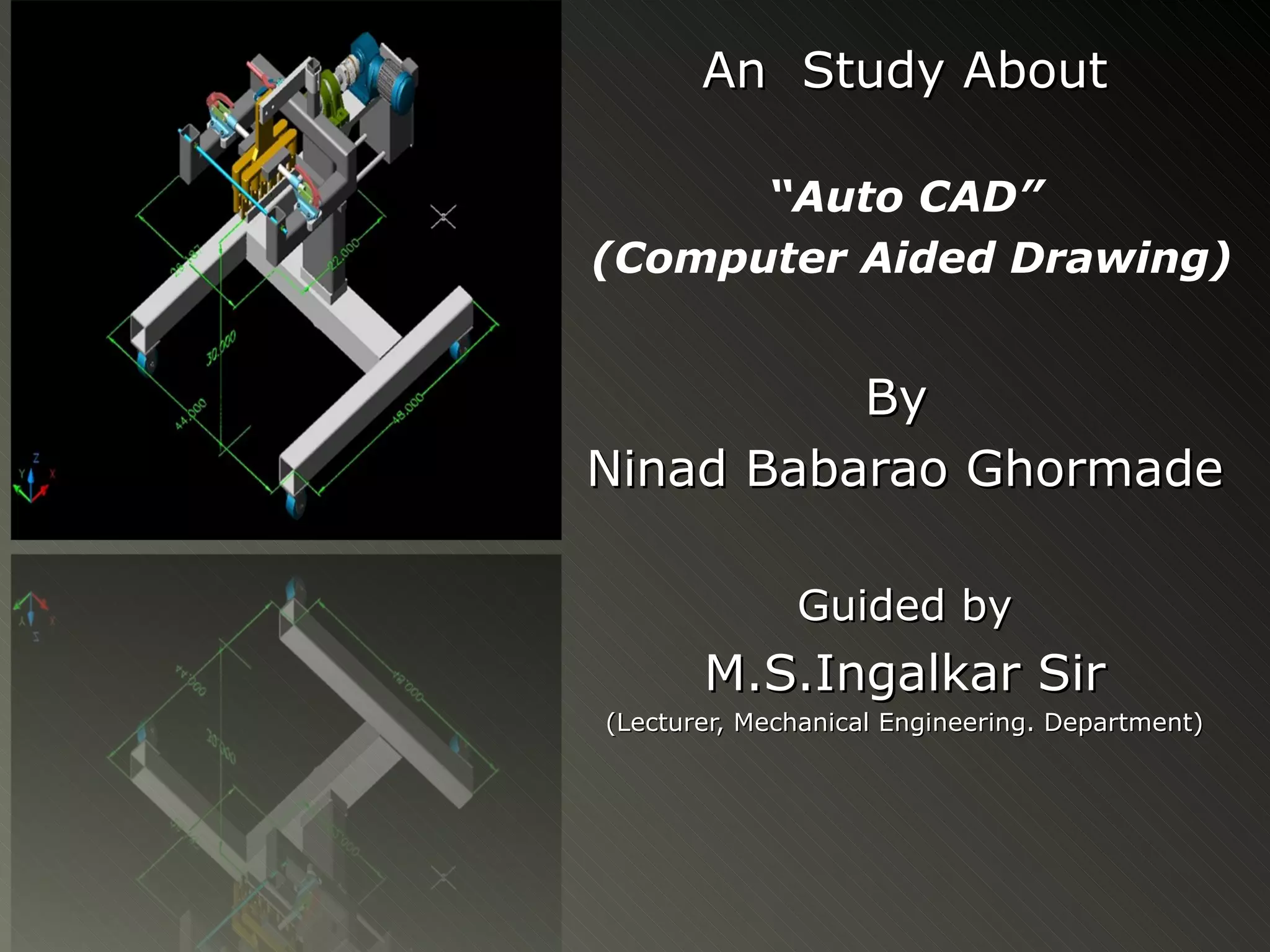
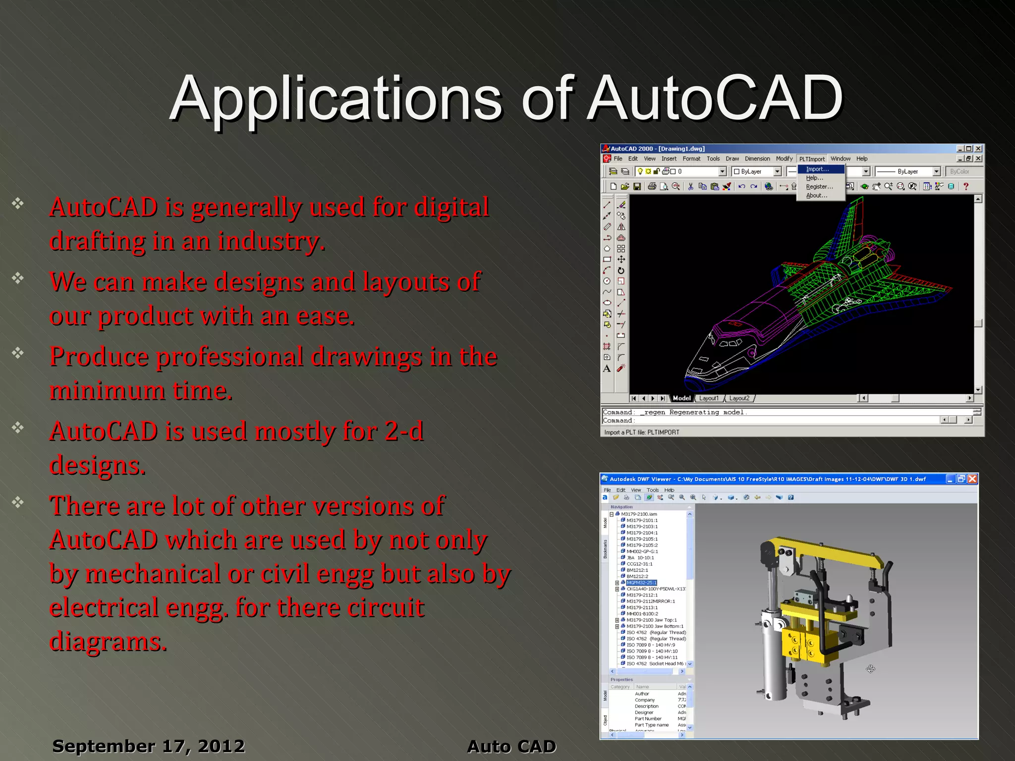
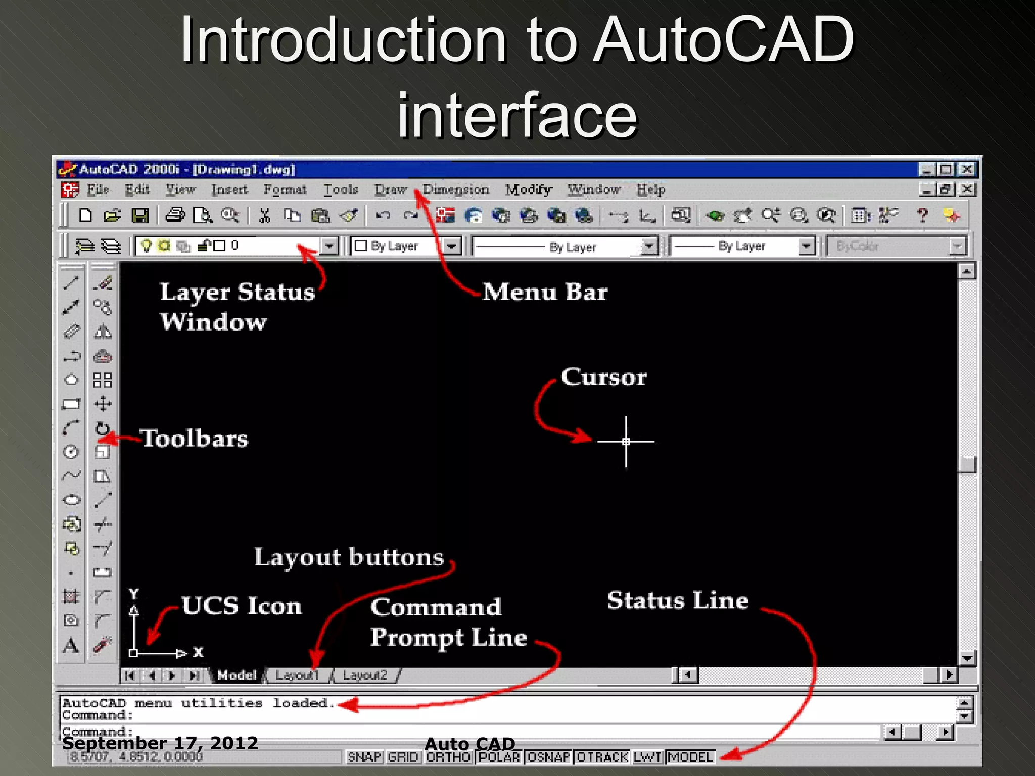
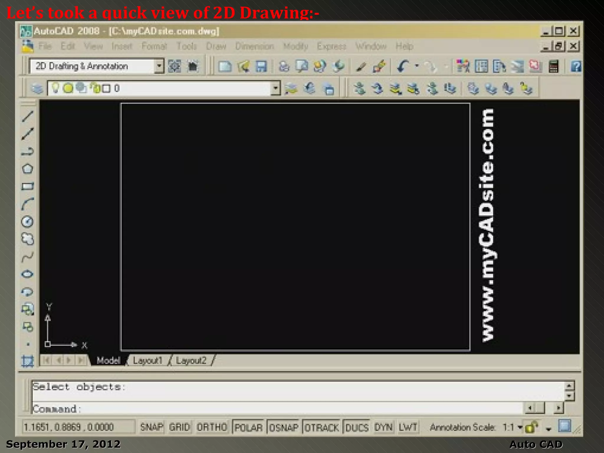
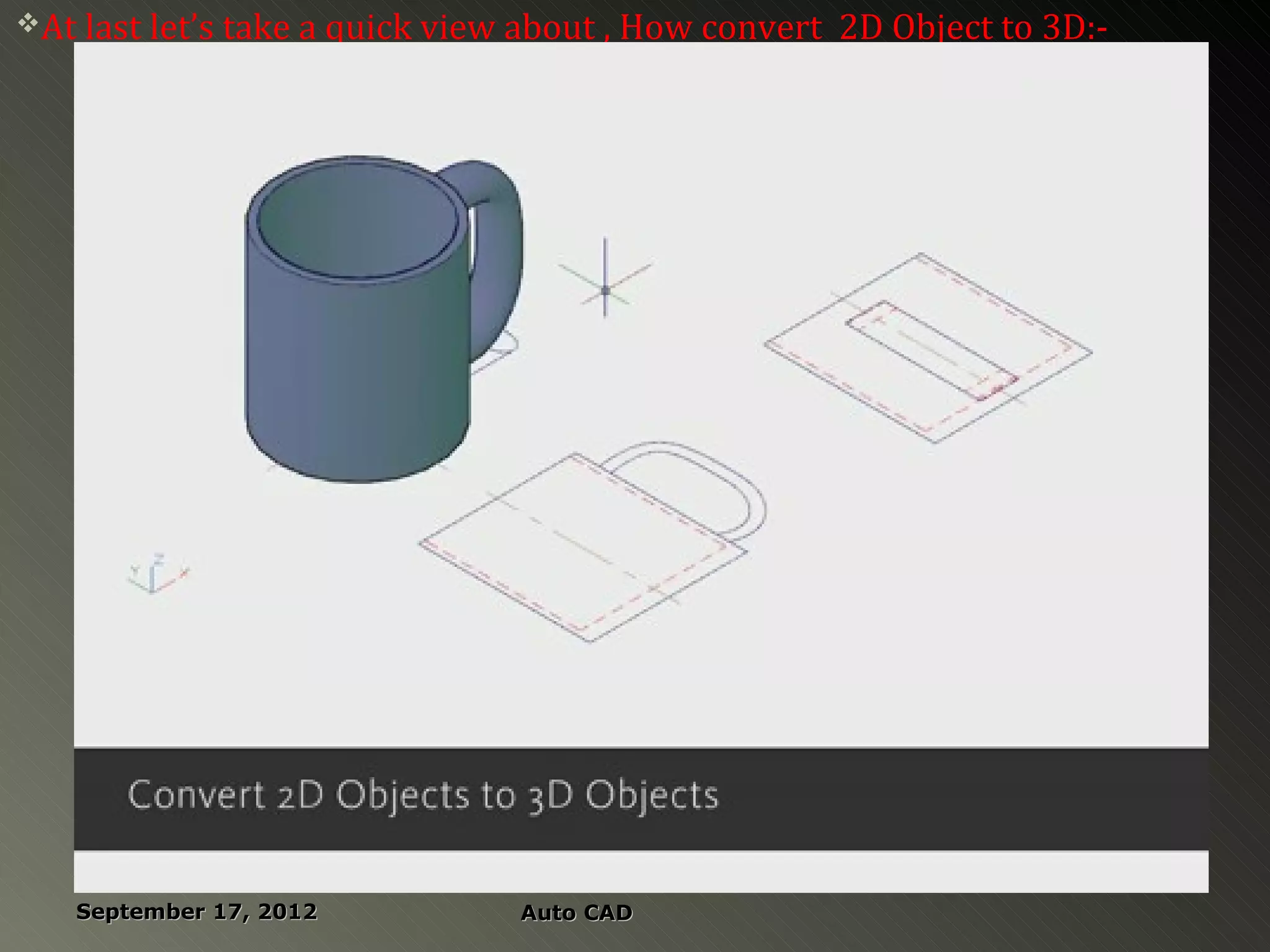
An Study About

      “Auto CAD”
(Computer Aided Drawing)


          By
Ninad Babarao Ghormade

              Guided by
       M.S.Ingalkar Sir
(Lecturer, Mechanical Engineering. Department)
Summary


September 17, 2012   Auto CAD
Introduction
   AutoCAD is a CAD software application for 2D and 3D design and

    drafting.

   It was developed and sold by Autodesk, Inc. First released in

    December 1982.

   Autodesk was founded in 1982 in USA by John walker.

   Some of its finest products are AutoCAD,3ds Max,

    Alias studio,Autodesk ECS Luster, MAYA and many more.


    September 17, 2012                              Auto CAD
   AutoCAD Is one of the basic software


   Now a days more advanced softwares like proE,catia,solid

    works etc are used in industry.


   AutoCAD basically used for 2-d modeling .


   The latest version of AutoCAD is AutoCAD-2013 and

    company is ready for its advanced version called AutoCAD-

    2014 with some new added features.

September 17, 2012             Auto CAD
Applications of AutoCAD
   AutoCAD is generally used for digital
    drafting in an industry.
   We can make designs and layouts of
    our product with an ease.
   Produce professional drawings in the
    minimum time.
   AutoCAD is used mostly for 2-d
    designs.
   There are lot of other versions of
    AutoCAD which are used by not only
    by mechanical or civil engg but also by
    electrical engg. for there circuit
    diagrams.


    September 17, 2012                 Auto CAD
Introduction to AutoCAD
                  interface


September 17, 2012   Auto CAD
Some basic facts and terms in
                   Autocad ….
    Autocad is always written as
     AutoCAD
    There are many ways of doing the
     same thing in AutoCAD.
    The ISO standard size of the sheet is                (420,
     420 X 297mm.                                        290)
    The background on which we draw
     is known as GUI(Graphical User
     Interface).
    The pointer is known as crosshair.
                                                    (0
    The UCS stands for user co-ordinate
                                                  ,0)
     system which shows the different x,y
     and z planes.


    September 17, 2012                 Auto CAD
SELECTION            PANEL OF Auto CAD

      When we move our cross here from left to right

       then BLUE area is formed and when we move it

       from right to the left then GREEN area is formed.


September 17, 2012        Auto CAD
X, Y Coordinate System
   Every object is located
    in relation to the
    origin.

   Positive and negative
    X axis

   Positive and negative
    Y axis

    September 17, 2012
                              Auto CAD
How to enter commands

   By clicking Menu item

   By clicking Toolbar icon

   By typing in Command line


September 17, 2012   Auto CAD
Commands used in autocad
   Circle :- draw    circle  options
        use Circle button on Draw Toolbar.
    Or by typing C in command prompt and then
    enter.


September 17, 2012                        Auto CAD
Ellipse:

   Draw > ellipse > center

             Home tab > draw panel > center

     Type ELLIPSE and then enter
   in command prompt.


September 17, 2012        Auto CAD
Trim:-   {TR enter}
        Trim command is used to delete the extended parts of
 An object.
Extend:- {Ex enter}

      Extend command elongates an object to a boundary.

Grid:-   {By pressing f7 key}
             This is pattern of dots displayed on the screen
      to guide.
Offset:-   {offset/o enter}
        Offset an object(parallel) by a set distance.

  September 17, 2012         Auto CAD
Mirror:-{Mi enter}
          It creates a mirror image of an object
   or selection set.
Stretch:- {s enter}

         It stretches an object after you have selected a
  Portion of it.
Fillet:- {f enter}
      Creates a round corner between the two lines
 Chamfer:- {cha enter}

      Creates an angled corner between two lines.


 September 17, 2012       Auto CAD
Array:- {AR enter}
          Creates a repeating pattern of the selected
Object.
Zoom:- {Z enter or with scrolling}
          Zoom command gives you zoomed version of an object.

Revcloud:- {REV enter}
        A revision cloud is used to highlight something.
Hatch:- {H enter}
         Hatch is used to make shaded portion, it represents
  The cross-sectional area of an object.


September 17, 2012         Auto CAD
Object snap:- {OS enter/f3}

         This is a method of snapping to certain, precise points
  On an object.

Ortho mode:-          {f8 key}


  September 17, 2012              Auto CAD
Let’s took a quick view of 2D Drawing:-


September 17, 2012                        Auto CAD
At last let’s take a quick view   about , How convert 2D Object to 3D:-


    September 17, 2012              Auto CAD
References


   http://www.usa.autodesk.com

   http://en.wikipedia.org/wiki/AutoCAD

   http://www.sciencedaily.com


September 17, 2012   Auto CAD

AutoCAD by Ninad Ghormade

  • 1.
    An Study About “Auto CAD” (Computer Aided Drawing) By Ninad Babarao Ghormade Guided by M.S.Ingalkar Sir (Lecturer, Mechanical Engineering. Department)
  • 2.
  • 3.
    Introduction  AutoCAD is a CAD software application for 2D and 3D design and drafting.  It was developed and sold by Autodesk, Inc. First released in December 1982.  Autodesk was founded in 1982 in USA by John walker.  Some of its finest products are AutoCAD,3ds Max, Alias studio,Autodesk ECS Luster, MAYA and many more. September 17, 2012 Auto CAD
  • 4.
    AutoCAD Is one of the basic software  Now a days more advanced softwares like proE,catia,solid works etc are used in industry.  AutoCAD basically used for 2-d modeling .  The latest version of AutoCAD is AutoCAD-2013 and company is ready for its advanced version called AutoCAD- 2014 with some new added features. September 17, 2012 Auto CAD
  • 5.
    Applications of AutoCAD  AutoCAD is generally used for digital drafting in an industry.  We can make designs and layouts of our product with an ease.  Produce professional drawings in the minimum time.  AutoCAD is used mostly for 2-d designs.  There are lot of other versions of AutoCAD which are used by not only by mechanical or civil engg but also by electrical engg. for there circuit diagrams. September 17, 2012 Auto CAD
  • 6.
    Introduction to AutoCAD interface September 17, 2012 Auto CAD
  • 7.
    Some basic factsand terms in Autocad ….  Autocad is always written as AutoCAD  There are many ways of doing the same thing in AutoCAD.  The ISO standard size of the sheet is (420, 420 X 297mm. 290)  The background on which we draw is known as GUI(Graphical User Interface).  The pointer is known as crosshair. (0  The UCS stands for user co-ordinate ,0) system which shows the different x,y and z planes. September 17, 2012 Auto CAD
  • 8.
    SELECTION PANEL OF Auto CAD  When we move our cross here from left to right then BLUE area is formed and when we move it from right to the left then GREEN area is formed. September 17, 2012 Auto CAD
  • 9.
    X, Y CoordinateSystem  Every object is located in relation to the origin.  Positive and negative X axis  Positive and negative Y axis September 17, 2012 Auto CAD
  • 10.
    How to entercommands  By clicking Menu item  By clicking Toolbar icon  By typing in Command line September 17, 2012 Auto CAD
  • 11.
    Commands used inautocad  Circle :- draw circle options use Circle button on Draw Toolbar.  Or by typing C in command prompt and then enter. September 17, 2012 Auto CAD
  • 12.
    Ellipse: Draw > ellipse > center Home tab > draw panel > center  Type ELLIPSE and then enter in command prompt. September 17, 2012 Auto CAD
  • 13.
    Trim:- {TR enter} Trim command is used to delete the extended parts of An object. Extend:- {Ex enter} Extend command elongates an object to a boundary. Grid:- {By pressing f7 key} This is pattern of dots displayed on the screen to guide. Offset:- {offset/o enter} Offset an object(parallel) by a set distance. September 17, 2012 Auto CAD
  • 14.
    Mirror:-{Mi enter} It creates a mirror image of an object or selection set. Stretch:- {s enter} It stretches an object after you have selected a Portion of it. Fillet:- {f enter} Creates a round corner between the two lines Chamfer:- {cha enter} Creates an angled corner between two lines. September 17, 2012 Auto CAD
  • 15.
    Array:- {AR enter} Creates a repeating pattern of the selected Object. Zoom:- {Z enter or with scrolling} Zoom command gives you zoomed version of an object. Revcloud:- {REV enter} A revision cloud is used to highlight something. Hatch:- {H enter} Hatch is used to make shaded portion, it represents The cross-sectional area of an object. September 17, 2012 Auto CAD
  • 16.
    Object snap:- {OSenter/f3} This is a method of snapping to certain, precise points On an object. Ortho mode:- {f8 key} September 17, 2012 Auto CAD
  • 17.
    Let’s took aquick view of 2D Drawing:- September 17, 2012 Auto CAD
  • 18.
    At last let’stake a quick view about , How convert 2D Object to 3D:- September 17, 2012 Auto CAD
  • 19.
    References  http://www.usa.autodesk.com  http://en.wikipedia.org/wiki/AutoCAD  http://www.sciencedaily.com September 17, 2012 Auto CAD
  • 20.

Editor's Notes

  • #2 September 17, 2012
  • #6 September 17, 2012
  • #8 I September 17, 2012