This document provides an overview of the AutoCAD software, including:
- AutoCAD was first launched in 1982 by Autodesk as 2D and 3D modeling software.
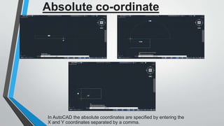
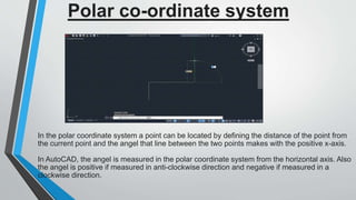
- It describes the AutoCAD screen and coordinate systems including absolute, relative, and polar.
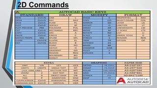
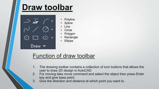
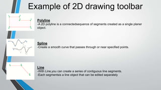
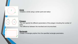
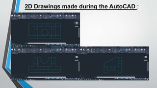
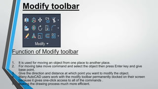
- Common 2D commands are explained like polyline, spline, line, circle, and modify tools like move, copy, trim, and stretch.
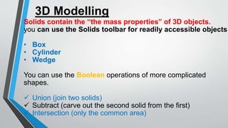
- 3D modeling in AutoCAD includes solids, boxes, cylinders, and Boolean operations.
- Isometric views are discussed and it concludes that AutoCAD has become very useful across industries.