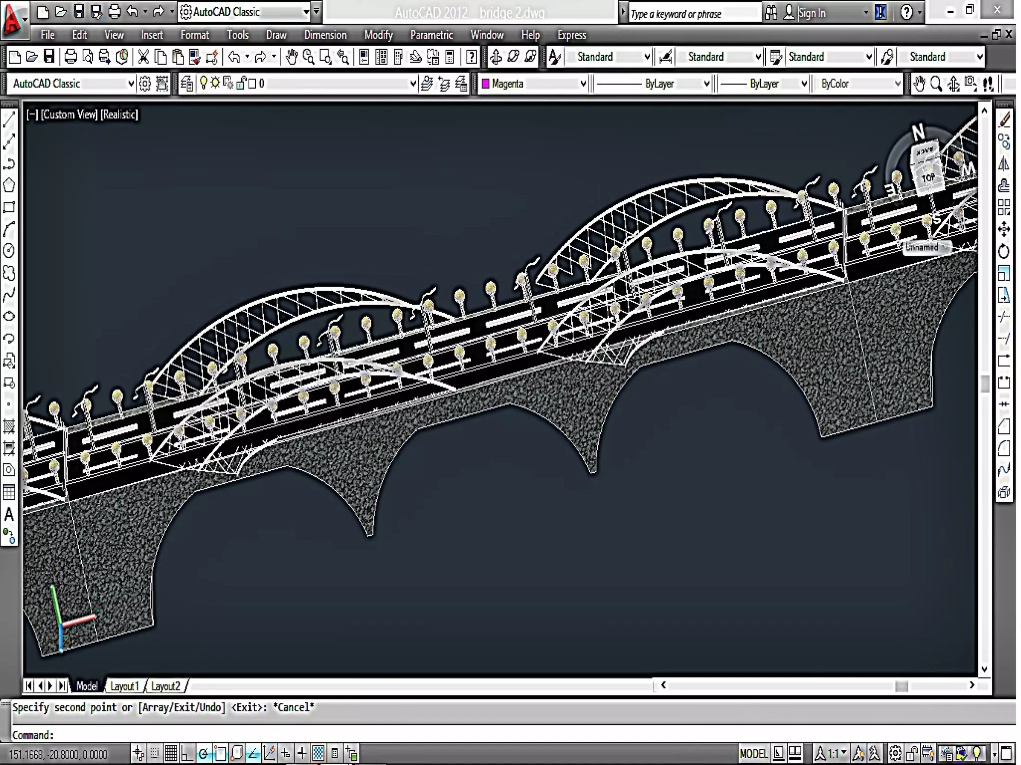
AutoCAD is a computer-aided design software developed by Autodesk, first released in December 1982, that supports 2D and 3D design and drafting. The latest version is AutoCAD 2018, which improves user experience and includes commands for versatile drawing techniques. Key features include various coordinate systems, 2D and 3D modeling commands, and benefits such as quick design creation and improved accuracy over manual drafting.


![AutoCAD is a CAD (Computer Aided Design or Computer Aided
Drafting) software application for 2D and 3D design and drafting.
Software application forSoftware application for CComputeromputer AAidedided DDesign &esign & DDraftingrafting
[[ CADDCADD .].]
Developed & Sold byDeveloped & Sold by AUTODESK INCAUTODESK INC. ,. , USAUSA ..
First released inFirst released in DecemberDecember 19821982 byby AUTODESKAUTODESK ..
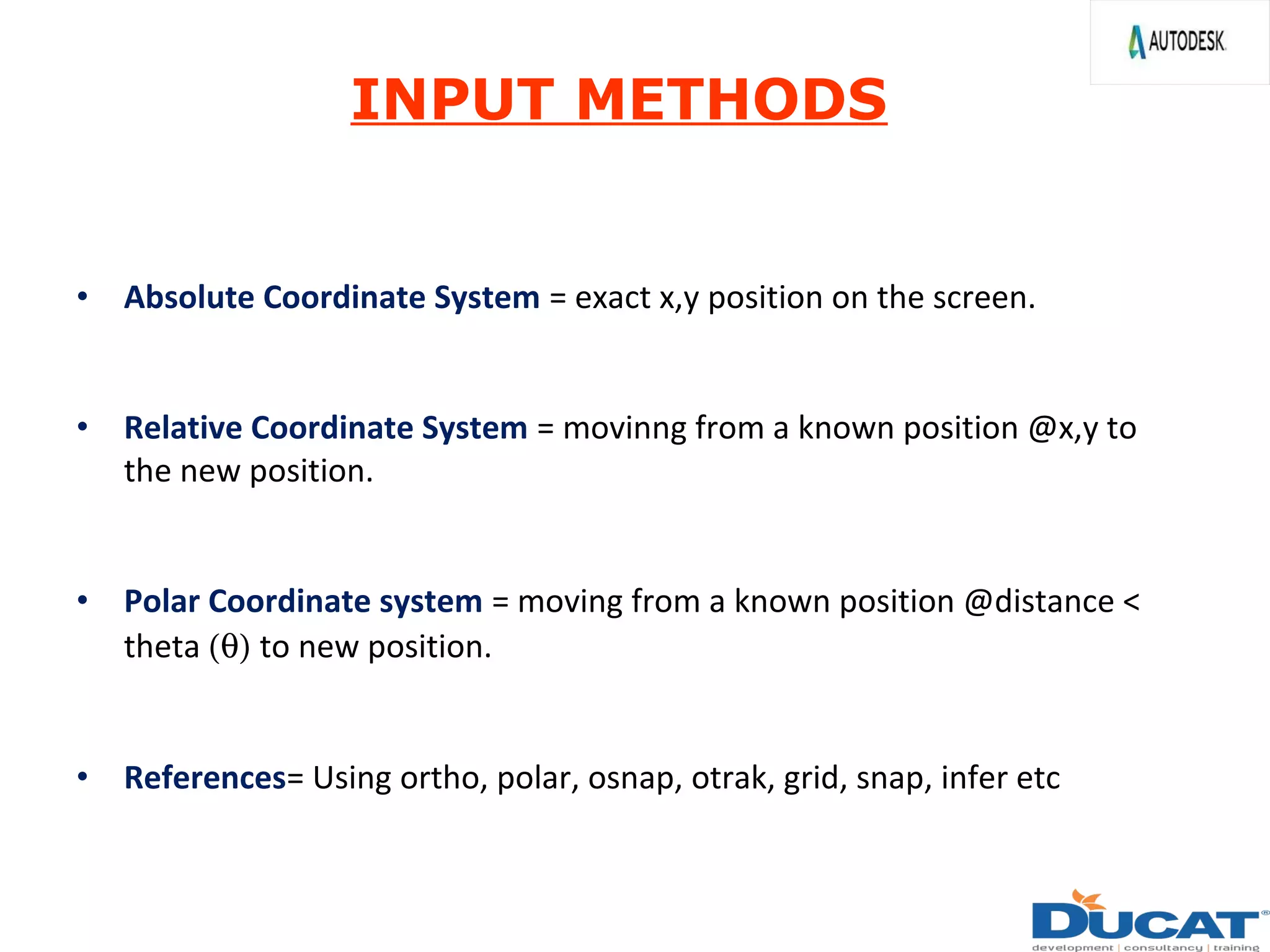
SupportsSupports 2D2D && 3D3D Co-ordinate System .Co-ordinate System .
Latest version isLatest version is AutoCAD 2018.AutoCAD 2018.
INTRODUCTION](https://image.slidesharecdn.com/autocadlatest-171019162836/75/Autocad-Prsentation-3-2048.jpg)


![Moho Pro 14.4 Crack for MacOS Works Until 2050 [Latest] pptx](https://cdn.slidesharecdn.com/ss_thumbnails/softwareoverview-251207192639-797289c4-thumbnail.jpg?width=640&height=640&fit=bounds)

![iStat Menus 7.20 Crack for MacOS 2026 Full Version [Latest] pptx](https://cdn.slidesharecdn.com/ss_thumbnails/softwareoverview-251207191544-22b737dc-thumbnail.jpg?width=640&height=640&fit=bounds)
![AnyTrans for iOS 8.9.14.20251127 With Crack for MacOS [Latest] pptx](https://cdn.slidesharecdn.com/ss_thumbnails/softwareoverview-251207190907-2316965f-thumbnail.jpg?width=640&height=640&fit=bounds)
![Driver Easy Pro Key 7.1.0.2641 Full Mac Crack Free Activated Download [2026]....](https://cdn.slidesharecdn.com/ss_thumbnails/software-251207185324-b2fb71b4-thumbnail.jpg?width=640&height=640&fit=bounds)

![Wondershare Filmora 15.0.11 Crack for Mac Key Full Download [Latest] pptx](https://cdn.slidesharecdn.com/ss_thumbnails/software-251207184836-1d16ba16-thumbnail.jpg?width=640&height=640&fit=bounds)


