OUTLIN
E
Introduction
LatestVersion
AutoCAD Screen
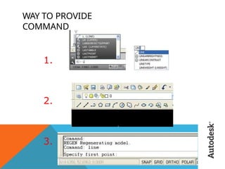
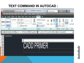
Way to provide command.
How it Works
Co-ordinate system.
Toolbars
Some 2D command.
3D Modeling
Some 3D Commands
Isometric view.
Project work
Benefits of AutoCAD.
3.
INTRODUCTI
ON
The WordAutoCAD is made up of two words “Auto(logo of company)”and
CAD “(computer aided design)”.
AutoCAD is 2D and 3D modeling software.
It is developed by Autodesk company.
Autodesk is an U.S.A based company.
It is widely used in industry for 2D drawing and 3D modeling.
In another way we can say that AutoCAD is a designing course , which is
performed by the help of computer.
4.
VERSION OF
AUTOCAD
AutoCADsoftware was firstly launched by Autodesk company in Dec. 1982.
It comes in India in 1988.
The first version of AutoCAD was R1 after that R2,R3,R4…………… and so
on.
In 2000,Autodesk launched a version of AutoCAD 2000 after that
2001,2002…… so on.
This time, we have the latest version of AutoCAD is 2014,which
is launched
on 27th march 2013.
Latest version is easy to use and over come the difficulties of old
version.
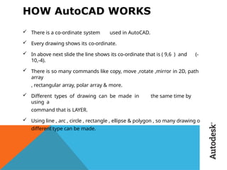
HOW AutoCAD WORKS
There is a co-ordinate system used in AutoCAD.
Every drawing shows its co-ordinate.
In above next slide the line shows its co-ordinate that is ( 9,6 ) and (-
10,-4).
There is so many commands like copy, move ,rotate ,mirror in 2D, path
array
, rectangular array, polar array & more.
Different types of drawing can be made in the same time by
using a
command that is LAYER.
Using line , arc , circle , rectangle , ellipse & polygon , so many drawing of
different type can be made.
9.
CO-ORDINATE
SYSTEM
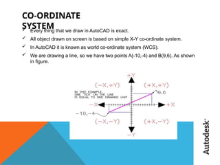
Every thingthat we draw in AutoCAD is exact.
All object drawn on screen is based on simple X-Y co-ordinate system.
In AutoCAD it is known as world co-ordinate system (WCS).
We are drawing a line, so we have two points A(-10,-4) and B(9,6). As shown
in figure.
10.
The UCS andWCS
The AutoCAD world is 3 dimensional. However, if we want to draw a 2d
object, such as a plan or a section, we will use only 2 dimensions (x and y).
WCS (world coordinate system) is the imaginary plane that is parallel to the
ground. It is the default coordinate system.
Modifications made to the World Coordinate System (WCS) result in a User
Coordinate System (UCS). It is the plane that you work on. It enables the
user to draw 3 dimensional objects.
To create a new UCS, type ucs on the command window, then say New and
specify 3 points on your new UCS plane.
11.
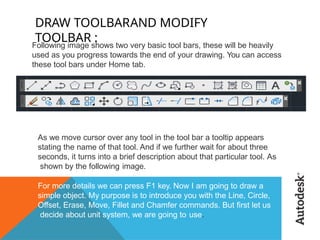
DRAW TOOLBARAND MODIFY
TOOLBAR:
Following image shows two very basic tool bars, these will be heavily
used as you progress towards the end of your drawing. You can access
these tool bars under Home tab.
As we move cursor over any tool in the tool bar a tooltip appears
stating the name of that tool. And if we further wait for about three
seconds, it turns into a brief description about that particular tool. As
shown by the following image.
For more details we can press F1 key. Now I am going to draw a
simple object. My purpose is to introduce you with the Line, Circle,
Offset, Erase, Move, Fillet and Chamfer commands. But first let us
decide about unit system, we are going to use.
12.
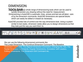
DIMENSION
TOOLBAR :
AutoCAD providesa whole range of dimensioning tools which can be used to
quickly dimension any drawing without the need for measurement.
Dimensioning in AutoCAD is automatic; lines, arrows and text are all taken care
of by the dimension commands. AutoCAD dimensions are special blocks
which can easily be edited or erased as necessary.
AutoCAD provides lots of control over the way dimensions look. Using a system
similar to text styles, dimension styles allow you to design dimensions so that
they look just the way you want them to.
We can use the following dimensional commands like
The Linear Dimension, The Continue Dimension Command, The Baseline
Dimension Command, The Aligned Dimension Command, Changing the Text, The
Radial Dimension Commands, Angular Dimensions, Annotation with Leaders,
Editing Dimensions, The Dimension Edit Command etc.
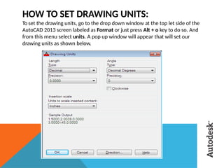
HOW TO SETDRAWING UNITS:
To set the drawing units, go to the drop down window at the top let side of the
AutoCAD 2013 screen labeled as Format or just press Alt + o key to do so. And
from this menu select units. A pop up window will appear that will set our
drawing units as shown below.
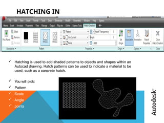
HATCHING IN
AUTOCAD
:
Hatchingis used to add shaded patterns to objects and shapes within an
Autocad drawing. Hatch patterns can be used to indicate a material to be
used, such as a concrete hatch.
You will pick:
Pattern
Scale
Angle
points
18.
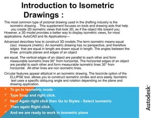
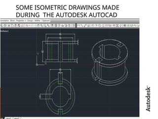
Introduction to Isometric
Drawings:
The most common type of pictorial drawing used in the drafting industry is the
isometric drawing. . This supplement focuses on tools and drawing aids that help
you create 2D isometric views that look 3D, as if the object tilts toward you.
However, a 3D model provides a better way to display isometric views, for most
applications. AutoCAD and Its Applications—
Advanced describes how to construct 3D models.The term isometric means equal
(iso) measure (metric). An isometric drawing has no perspective, and therefore
edges that are equal in length are drawn equal in length. The angles between the
three principle planes and edges of an object
are equal. The vertical edges of an object are parallel to each other and form
measurable isometric lines 90° from horizontal. The horizontal edges of an object
are parallel to each other and form measurable isometric lines 30° from
horizontal. All other lines are non isometric lines.
Circular features appear elliptical in an isometric drawing. The Isocircle option of the
ELLIPSE tool, allows you to construct isometric circles and arcs easily. Isometric
text uses a specific obliquing angle and rotation depending on the plane and
drawing application.
To go to Isometric mode :
Type Snap and right click.
Next Again right click then Go to Styles - Select isometric
Then again Right click .
And we are ready to work in isometric plane
INTRODUCTION TO
3D:
3D capabilitiesallow you to draw pictorial views such as isometrics, oblique
views and perspectives. The views drawn with CADD have a number of
advantages as compared to views drawn on a drawing board. The views drawn
with CADD are very accurate and provide a lot of flexibility in terms of editing
and display. You can rotate a model on the screen just like an actual model, and
display views from different angles. CADD provides special 3D functions that
allow you to create 3D drawings that are true representations of an actual
model. These drawings can be viewed from any angle just like a physical model.
That is why 3D CADD drawings are called 3D models.
The major distinction between a 2D drawing and a 3D model is that a 2D
drawing is defined only with two coordinates (X and Y). A 3D model is defined
with three coordinates (X, Y and Z). The Z-coordinate determines the height of
an object. To make a 3D model, you need to consider all the objects of the
model in 3D space and enter the X, Y and Z coordinates for all drawing objects.
21.
3D
MODELING
Solids contain the“mass properties” of 3D objects.
You can use the Solids toolbar for readily accessible
objects
Box
Cylinder
Wedge
You can use the Boolean operations of more
complicated shapes.
Union (join two solids)
Subtract (carve out the second solid from the first)
Intersection (only the common area)
23.
3D
COMMANDS
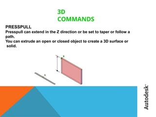
PRESSPULL
Presspull can extendin the Z direction or be set to taper or follow a
path.
You can extrude an open or closed object to create a 3D surface or
solid.
24.
USE OF EXTRUDE
COMMAND
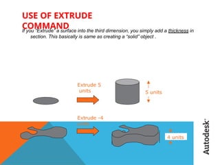
Ifyou “Extrude” a surface into the third dimension, you simply add a thickness in
section. This basically is same as creating a “solid” object .
Extrude 5
units 5 units
Extrude -4
units
4 units
BENEFITS/USE OF
AUTOCAD
Quicklycreate designs.
Improved quality over hand drafting.
Easily modify.
More Accuracy.
Easy to transfer.
Long time save.