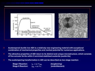
   Austempered ductile iron ADI is a relatively new engineering material with exceptional
    combination of mechanical properties and marked potential for numerous applications.

   The attractive properties of ADI return to its distinct and unique microstructure, which consists
    of fine acicular ferrite within C-enriched stabilized austenite (ausferrite)

   The austempering transformation in ADI can be described as two stage reaction:

         Stage I Reaction:     o   + HC          (toughening)
         Stage II Reaction:    HC   +            (embrittlement)
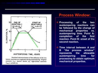
Process Window:
 Processing     of   the    two
  austempering reactions can
  be followed by the change of
  mechanical properties vs.
  austempering time. Point A:
  completion     of   the    first
  reaction. Point B: onset of the
  second reaction.

 Time interval between A and
  B “the process window”
  represents    the    allowable
  austempering      time     for
  processing to obtain optimum
  mechanical properties.
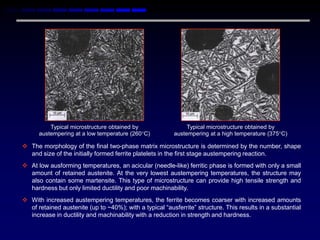
Typical microstructure obtained by                  Typical microstructure obtained by
      austempering at a low temperature (260C)          austempering at a high temperature (375C)

 The morphology of the final two-phase matrix microstructure is determined by the number, shape
  and size of the initially formed ferrite platelets in the first stage austempering reaction.
 At low ausforming temperatures, an acicular (needle-like) ferritic phase is formed with only a small
  amount of retained austenite. At the very lowest austempering temperatures, the structure may
  also contain some martensite. This type of microstructure can provide high tensile strength and
  hardness but only limited ductility and poor machinability.
 With increased austempering temperatures, the ferrite becomes coarser with increased amounts
  of retained austenite (up to ~40%); with a typical “ausferrite” structure. This results in a substantial
  increase in ductility and machinability with a reduction in strength and hardness.
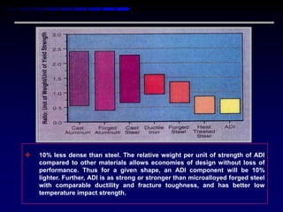
   10% less dense than steel. The relative weight per unit of strength of ADI
    compared to other materials allows economies of design without loss of
    performance. Thus for a given shape, an ADI component will be 10%
    lighter. Further, ADI is as strong or stronger than microalloyed forged steel
    with comparable ductility and fracture toughness, and has better low
    temperature impact strength.
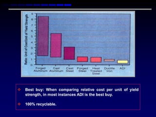
   Best buy: When comparing relative cost per unit of yield
    strength, in most instances ADI is the best buy.

   100% recyclable.
THE PRODUCTION OF ADI


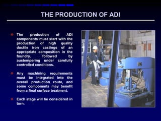
 The     production     of  ADI
  components must start with the
  production of high quality
  ductile iron castings of an
  appropriate composition in the
  foundry,      followed      by
  austempering under carefully
  controlled conditions.

 Any machining requirements
  must be integrated into the
  overall production route, and
  some components may benefit
  from a final surface treatment.

 Each stage will be considered in
  turn.
Foundry Production

The main change in foundry practice when
producing castings for austempering is to
ensure that the ductile iron is correctly alloyed
to allow the required microstructure to be
developed    during   the   austempering     heat
treatment. The critical stage is the quench from
the austenitizing temperature to the isothermal
transformation (austempering) temperature.
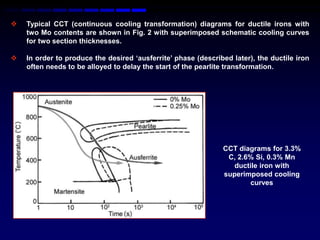
   Typical CCT (continuous cooling transformation) diagrams for ductile irons with
    two Mo contents are shown in Fig. 2 with superimposed schematic cooling curves
    for two section thicknesses.

   In order to produce the desired „ausferrite‟ phase (described later), the ductile iron
    often needs to be alloyed to delay the start of the pearlite transformation.


                                                               CCT diagrams for 3.3%
                                                                C, 2.6% Si, 0.3% Mn
                                                                  ductile iron with
                                                               superimposed cooling
                                                                       curves
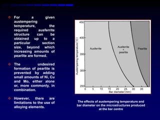
 For        a        given
  austempering
  temperature,          the
  required        ausferrite
  structure      can     be
  obtained     up    to    a
  particular        section
  size, beyond which
  increasing amounts of
  pearlite are formed.

 The          undesired
  formation of pearlite is
  prevented by adding
  small amounts of Ni, Cu
  and Mo, either alone
  or, more commonly, in
  combination.

 However,     there    are
  limitations to the use of    The effects of austempering temperature and
                               bar diameter on the microstructures produced
  alloying elements.
                                              at the bar centre
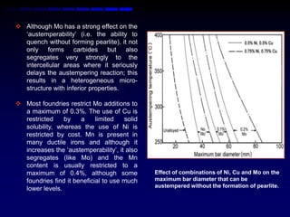
 Although Mo has a strong effect on the
  „austemperability‟ (i.e. the ability to
  quench without forming pearlite), it not
  only forms carbides but also
  segregates very strongly to the
  intercellular areas where it seriously
  delays the austempering reaction; this
  results in a heterogeneous micro-
  structure with inferior properties.

 Most foundries restrict Mo additions to
  a maximum of 0.3%. The use of Cu is
  restricted    by    a     limited   solid
  solubility, whereas the use of Ni is
  restricted by cost. Mn is present in
  many ductile irons and although it
  increases the „austemperability‟, it also
  segregates (like Mo) and the Mn
  content is usually restricted to a
  maximum of 0.4%, although some              Effect of combinations of Ni, Cu and Mo on the
  foundries find it beneficial to use much    maximum bar diameter that can be
                                              austempered without the formation of pearlite.
  lower levels.
 The following recommendations have been made for the
  composition of ductile iron suitable for austempering:

  C:    3.60% ( 0.2%)

  Si:          2.50% ( 0.20%)

  Mn: < 0.35% ( 0.05%)               for section size > 13 mm

        or < 0.60% ( 0.05%)   for section size < 13 mm

  Cu: < 0.80 ( 0.05%)

  Ni: < 2.00% ( 0.10%)

  Mo: < 0.30% ( 0.03%)
 It should be noted that the alloying additions suggested were
  obtained by quenching simple shapes into a well-agitated salt
  bath where the volume of salt greatly exceeded the volume of
  castings being quenched.

 In industrial production, the metal:salt ratio will be considerably
  higher and components may be more complex; both factors will
  result in a reduced quench rate which may necessitate higher
  alloy addi-tions. On the other hand, some commercial
  austem-pering companies add water to the salt to increase the
  quench rate and a technique has been developed to super-
  saturate the salt with water.

 This enables the alloy addition to be reduced with obvious
  economic benefits.

 It is therefore important that the person selecting the alloy
  composition (usually the foundry) liaises closely with the heat
  treater.
 Although careful attention must be given to all stages of the
  production of any ductile iron casting, this is even more
  important in the case of components which are to be
  austempered.

 One guideline is that the nodule count should be ≥ 100
  nodules/mm2 to minimise an uneven response to austempering
  caused by the micro-segregation of alloying elements; the
  foundry should exploit modern inoculation methods and
  materials to achieve this.

 The the nodularity should be ≥ 90%, the carbide and inclusion
  content should be ≤ 0.5%, and the porosity should be ≤ 1%.

 The foundry should exploit techniques such as computer
  simulation and filters to help them to achieve these targets.
 It is often beneficial for the foundry to  Some have found it effective to anneal
  ensure a consistent as-cast structure       the castings prior to machining since the
  so that the microstructural re-sponse       lower hardness ferritic matrix increases
  and dimensional changes during              machinability and the dimensional
  austempering are reproducible.              changes during austempering are
                                              consistent.
 The phase change during heat
  treatment results in growth of the
  castings by an amount which depends
  on the initial (as-cast) microstructure
  and the austempering temperature.


 Hence, if the as-cast structure
  varies, the dimensional change during
  aus-tempering will not be consistent.


 In some cases, it is wished to machine
  the castings before austempering but
  this is only feasible if the growth is      Effect of initial structure and austempering
  predictable.                                temperature on the change in diameter of a 150
                                              mm diameter disc.
Heat Treatment

Process:

 In the conventional austempering process, castings are firstly heated into the
  austenite phase field and held for long enough to ensure a fully austenitic matrix
  structure with a uniform carbon content.

 The latter is a function of the austenitizing temperature and affects the
  subsequent transformation to ausferrite.

 Typical parameters are 1 hour at
  900C. However, it should be
  noted that the upper critical
  temperature      varies     with
  composition, particularly the Si
  content, so this must be
  adequately controlled to avoid
  the need to adjust the
  austenitizing temperature
                                                Typical austempering cycle used for ductile
                                                                   iron
 The austenitising time depends on 3 main variables:


                                            •    The section thickness: thicker
                                                 sections will need to be „soaked‟ for
                                                 longer times;


                                            •    The nodule count: high nodule
                                                 counts reduce the austenitizing time
                                                 since they reduce the distance that
                                                 C needs to diffuse to obtain a
                                                 uniform C content;


                                            •    The        initial   microstructure:
Section of the Fe-C-2% Si equilibrium            austenitization occurs more rapidly
phase diagram
                                                 in a pearlitic as-cast matrix
                                                 structure.


 In some cases, austenitisation is deliberately carried out in the α +  range so
  that the final microstructure contains some proeutectoid ferrite to improve
  machinability.
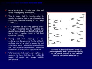
   Once austenitized, castings are quenched
    to the austempering temperature.
   This is below that for transformation to
    pearlite and above that for transformation to
    martensite (Ms) and usually in the range
    235-400C.

   It is important to miss the pearlite „nose‟
    (Fig. 2) by ensuring that the castings are
    appropriately alloyed and transferred rapidly
    into a quench medium having a high heat
    extraction capability.
   During      isothermal      holding     at   the
    austempering temperature, ferrite platelets
    nucleate and grow into the austen-ite and
    the excess carbon (arising from the different
    solid solubilities of C in ferrite and austenite)
    diffuses into the untransformed austenite.            Schematic illustration of bainitic ferrite ()
                                                        platelets growing from a grain boundary (GB)
   Whereas in steels the carbon precipitates as         into the original austenite (o) and creating
    carbides to form „bainite‟, the higher Si                zones of high-carbon austenite (HC)
    content of ductile iron delays carbide
    precipitation.
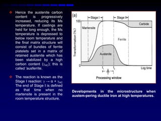
 Hence the austenite carbon
  content     is    progressively
  increased, reducing its Ms
  temperature. If castings are
  held for long enough, the Ms
  temperature is depressed to
  below room temperature and
  the final matrix structure will
  consist of bundles of ferrite
  platelets set in a matrix of
  retained austenite which has
  been stabilized by a high
  carbon content (HC); this is
  called „ausferrite.

 The reaction is known as the
  Stage I reaction:  → α + HC
  The end of Stage I is defined
  as that time when no              Developments in the microstructure when
  martensite is present in the      austem-pering ductile iron at high temperatures.
  room temperature structure.
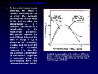
 As the austempering time is
  extended, the Stage II
  reaction eventually occurs
  in which the austenite
  decomposes to form more
  ferrite and carbides are
  precipitated: HC → α +
  carbides. This results in a
  deterioration     in    the
  mechanical      properties.
  The period between the
  end of Stage I (t1) and the
  start of Stage II (t2) is
  known as the „processing
  window‟ and has been the
  subject     of   extensive
  research. It is clear that
  the optimum combination       Idealized characterization of the influence of the two
  of mechanical properties      bainite reactions on toughness during austempering.
  is achieved when the          Original austenite (o), bainitic ferrite (), high-carbon
                                austenite (HC), carbide (c)
  austempering time falls
  between these two values.
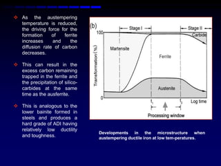
 As the austempering
  temperature is reduced,
  the driving force for the
  formation     of   ferrite
  increases     and     the
  diffusion rate of carbon
  decreases.

 This can result in the
  excess carbon remaining
  trapped in the ferrite and
  the precipitation of silico-
  carbides at the same
  time as the ausferrite.

 This is analogous to the
  lower bainite formed in
  steels and produces a
  hard grade of ADI having
  relatively low ductility
                                 Developments in the microstructure when
  and toughness.                 austempering ductile iron at low tem-peratures.
 A variety of ausferritic matrix structures
  with different amounts and distributions
  of ferrite and retained austenite can be
  produced, particularly by varying the
  austempering       temperature.     These
  different    structures    control     the
  mechanical properties obtained.

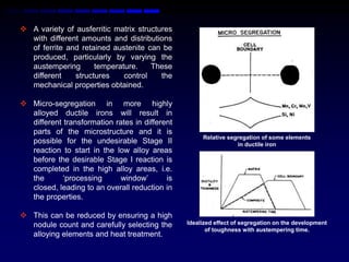
 Micro-segregation in more highly
  alloyed ductile irons will result in
  different transformation rates in different
  parts of the microstructure and it is
                                                     Relative segregation of some elements
  possible for the undesirable Stage II                          in ductile iron
  reaction to start in the low alloy areas
  before the desirable Stage I reaction is
  completed in the high alloy areas, i.e.
  the       „processing      window‟       is
  closed, leading to an overall reduction in
  the properties.

 This can be reduced by ensuring a high
  nodule count and carefully selecting the      Idealized effect of segregation on the development
                                                       of toughness with austempering time.
  alloying elements and heat treatment.
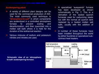
Austempering plant:                              A specialized „ausquench‟ furnace
                                                  has been developed as shown
 A variety of different plant designs can be     schematically in Fig. 7. This is a
  used for the commercial production of ADI.      derivation of the sealed quench
  The most commonly used technique is             furnaces used for carburizing steels
  “atmosphere-to-salt” in which components        but with the normal oil quench tank
  are austenitized in a controlled atmosphere     replaced by a heated molten salt
  furnace      to    prevent    scaling   and     bath, usually with the addition of
  decarburization, and then quenched into a       water.
  molten salt bath where it is held for the
  duration of the isothermal reaction.           A number of these furnaces have
                                                  been installed throughout the world
 Various mixtures of sodium and potassium        by either foundries or specialized sub-
  nitrides and nitrates are used.                 contract heat treaters.


 Schematic view of an „atmosphere-
to-salt‟ austempering furnace.
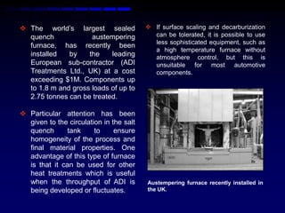
 The world‟s largest sealed              If surface scaling and decarburization
  quench             austempering          can be tolerated, it is possible to use
                                           less sophisticated equipment, such as
  furnace, has recently been
                                           a high temperature furnace without
  installed   by    the    leading         atmosphere control, but this is
  European sub-contractor (ADI             unsuitable for most automotive
  Treatments Ltd., UK) at a cost           components.
  exceeding $1M. Components up
  to 1.8 m and gross loads of up to
  2.75 tonnes can be treated.

 Particular attention has been
  given to the circulation in the salt
  quench      tank      to     ensure
  homogeneity of the process and
  final material properties. One
  advantage of this type of furnace
  is that it can be used for other
  heat treatments which is useful
  when the throughput of ADI is          Austempering furnace recently installed in
  being developed or fluctuates.         the UK.
 The second most commonly used technique is “salt-to-
  salt” in which the components are austenitized in a high
  temperature salt bath (containing sodium chloride and
  barium or potassium chloride) and then quenched into
  the nitrite/nitrate austemper-ing salt bath.

 Such an arrangement is less sophisticated and uses
  less expensive capital plant, but can provide a cost-
  effective means of austempering and has been used by
  various companies.

 There are various technical and economic advantages
  and disadvantages of the “atmosphere-to-salt” and “salt-
  to-salt” techniques and careful consideration must be
  given to these by any company wishing to enter this
  market.
 The first high volume automotive application of ADI was for
  rear axle gears used in cars produced by General Motors.
  After austenitizing in a multi-station „pusher‟ controlled
  atmosphere furnace, these were quenched and
  austempered at ~238 C using a hot oil which was specially
  developed for the purpose. Hot oil was also used when
  producing ADI timing gears for certain diesel engines
  manufactured by Cummins.

 The main limitation of using hot oil is the maximum
  austempering temperature of ~250 C which therefore
  restricts its use to the hardest grades of ADI. It has been
  suggested that it is possible to quench briefly into hot oil
  and then to transfer to an air muffle furnace set at a higher
  austempering temperature, but this idea does not appear to
  be used commercially.
 Molten salts have various disadvantages,
  particularly the need to ensure that components are
  thoroughly washed to remove all traces of salt which
  would otherwise lead to subsequent corrosion.
 This generates large volumes of salt-contaminated
  water and further equipment is then required to reclaim
  the salt before the water can be discharged.

 Although there has been some interest in using
  fluidized beds for both the austenitizing and
  austempering stages to avoid these environmental
  problems, the significantly lower quench rate appears
  to have precluded industrial use.
 It can be noted that some components only re-quire the
  austempered structure in particular areas, examples being
  the mating faces and roots of gear teeth and the surfaces of
  camshafts.

 The concept of „selective austempering‟ has therefore been
  developed in which induction heating is used to austenitized
  the area of interest prior to conventional quenching and
  isothermal transformation.

 An important advantage of this is the reduced heat treatment
  cycle time.

 CWC Textron (Muskegan, USA) has developed and patented
  a selective austempering technique for ductile iron camshafts
  as a cost-effective alternative to forged steel camshafts.
Hot Shake-out

 There has been some interest in removing castings from the mould
  whilst they are still hot, and charging them directly into the heat
  treatment line.

 As well as reducing the cycle time, there is the potential for significant
  energy savings since castings do not have to be re-austenitized
  (although it may be beneficial to hold them for a short time in an
  austenitizing furnace to improve the temperature homogeneity).

 This idea has re-surfaced in a recent EC-funded research project which
  has involved the use of squeeze casting to produce near-net shape
  castings with minimum porosity. It has been found that the mechanical
  properties exceed those of conventional ADI.
Machining

 When ADI first started to be used for engineering applications, there
  were many difficulties experienced in trying to machine it, and some of
  these doubtlessly persist to this day.

 The hardest grades of ADI reach a hardness of ~ 50 HRC which would
  pose a challenge for any high volume machining operation.

 Although the softer grades of ADI have a typical hardness of 300–350
  BHN, their matrix structure contains up to 40% retained austenite.
  When subjected to strains in service, this phase rapidly work hardens
  and can transform to martensite; this can thereby reduce the
  machinability compared with a steel of equivalent hardness.
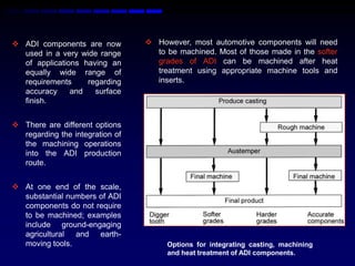
 ADI components are now          However, most automotive components will need
  used in a very wide range        to be machined. Most of those made in the softer
  of applications having an        grades of ADI can be machined after heat
  equally wide range of            treatment using appropriate machine tools and
  requirements     regarding       inserts.
  accuracy     and   surface
  finish.


 There are different options
  regarding the integration of
  the machining operations
  into the ADI production
  route.


 At one end of the scale,
  substantial numbers of ADI
  components do not require
  to be machined; examples
  include ground-engaging
  agricultural and earth-
  moving tools.                       Options for integrating casting, machining
                                      and heat treatment of ADI components.
 This becomes progressively more difficult as the hardness increases
  and it is often preferable to machine before heat treatment by making
  an allowance for the dimensional growth, assuming that this is
  predictable and that there is no significant distortion.

 If the dimensional growth is not sufficiently consistent, the only option
  is to do most of the machining before austempering, and to finish
  machine any critical dimensions after austempering.

 This can create logistical difficulties if the casting, machining and heat
  treatment are done by different companies located at some distance
  from each other.

 Nevertheless, this route has been widely used for ADI gears which
  must be extremely accurate for them to operate quietly and to have a
  long life.
 The North American approach has generally been to use a higher Mn
  base iron than in Europe to reduce the foundry costs, but the resulting
  ADI is harder to machine, so more than half of the ADI components
  produced in North America are finish machined before austempering.

 In contrast, many European ADI castings are machined after heat
  treatment.

 It is considered that the limited use of ADI for high volume applications
  is partly due to machining difficulties.

 There have been two different approaches to remedy this:

      To establish the best machining tools and conditions

      To develop machinable grades of ADI
Machining practice:
 One approach has been to optimize the machining
  operations, particularly the selection of the optimum cutting
  tools and parameters. A considerable amount of research
  has been done in this area and has been digested in the
  form of simplified guidelines.

 It is normally recommended that the aim should be to
  ensure that the tool cuts below the hardened surface layer
  in ADI by selecting a higher depth of cut (typically 50%
  more) and using a slower speed (typically 50% less) than
  would be used for a „conventional‟ material of the same
  hardness.
 Careful consideration should also be given to tool material and geometry
  and the use of cooling lubricants by discussion with appropriate
  suppliers.

   Examples:

        Silicon nitride ceramic with a multi-layer CVD coating gave the
         least wear when turning ADI 800 but CBN and PCD tools were not
         suitable,

        Wear resistant cemented carbides (K10, based on tungsten
         carbides) with wear resistant coating (Al2O3 TiCN or TiAlN) can be
         successfully used at low cutting speeds,

        Al2O3 ceramics, mixed ceramics and whisker-reinforced ceramic
         materials gave good results at higher cutting speeds.

 It is recommended that the work-piece must be rigidly clamped and a
  rigid tool-holder should be used to minimize vibration during machining
  and thereby reduce tool wear, improve surface finish and reduce
  dimensional variations.
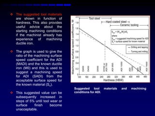
 The suggested tool materials
  are shown in function of
  hardness. This also provides
  useful advice about the
  starting machining conditions
  if the machinist already has
  experience    of   machining
  ductile iron.

 The graph is used to give the
  ratio of the machining surface
  speed coefficient for the ADI
  (MADI) and the known ductile
  iron (M0) and this is used to
  suggest a machining speed
  for ADI (SADI) from the
  acceptable surface speed for
  the known material (So).
                                   Suggested tool materials   and   machining
 This suggested value can be      conditions for ADI.
  subsequently increased in
  steps of 5% until tool wear or
  surface    finish      become
  unacceptable.
Machinable ADI:
 The other approach has been to optimize the composition and heat
  treatment to maximize the machinability. In the 1980‟s, Muhlberger
  developed and patented a machinable grade of ADI by careful
  selection of the composition (low Mn) and heat treatment
  variables, and at least one European foundry has exploited this
  development in commercial production.

 More recently, two grades of a machinable ADI have been developed
  in the US. These are specifically aimed at increasing the use of ADI for
  automotive applications such as chassis components and crankshafts.

 There are some differences between the two approaches, although the
  matrix structure contains a considerable amount of ferrite in both
  cases.

 The interest in machinable ADI has been confirmed in Europe to
  develop a mixed ferritic-ausferritic ductile iron for automotive
  suspension parts.
SURFACE TREATMENT

 Components treated at the higher end of the austempering
  temperature range also benefit from similar cold working
  treatments.

 In addition to any direct effect on the residual stresses, it
  appears that there may be an additional benefit from the
  compressive stresses brought about by the strain-induced
  transformation of retained austenite to martensite. This has
  been demonstrated in gears and crankshafts. The
  endurance limit of an ADI crankshaft could be increased
  from 414 MPa to 1,000 MPa by fillet rolling.

 Clearly, the use of these surface treatments will add further
  cost, so a careful cost benefit analysis should be carried out
  before applying them.
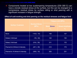
 Components treated at low austempering temperatures (235–300 C) can
  have a tensile residual stress at the surface, but this can be changed to a
  compressive residual stress by surface rolling or shot peening with a
  significant increase in fatigue strength.

Effect of cold working and shot peening on the residual stresses and fatigue limit

                                                         Fatigue Limit (MPa)
                                 Residual Stress
       Surface Treatment
                                     (MPa)         Mean Stress     Stress Amplitude,
                                                       m                  a


None                               +143 ( 10)         156                  127

Rolled, 5 kN load                    -78 ( 20)        183                  150
Rolled, 9 kN load                  -216 ( 29)          211                 172

Peened to 6 Almen A intensity      -241 ( 49)         212                  173


Peened to 16 Almen A intensity     -248 ( 10)         283                  231
Quality Control
 The successful production of reliable ADI components requires careful
  attention to ensure that the foundry, heat treatment and machining
  operations are carried out consistently.

 Although test bars are routinely processed with each batch of
  castings, one concern among some end-users is the difficulty of
  ensuring that every component meets the minimum specified
  properties.

 There has been some research on the use of non-destructive testing
  techniques to assess the microstructure and/or properties of ADI
  components.

 An extensive investigation has shown that multi-frequency eddy
  current testing is a powerful technique, although it cannot completely
  replace conventional tensile testing. This was used to check that every
  ADI upper control arm had been properly austempered.
PROPERTIES OF ADI

 There    have    been    many
  studies of the mechanical
  properties of ADI and it is
  clear that these depend on a
  number of interlinked factors.

 As well as the austenitizing
  and             austempering
  temperatures            and
  times, these include the as-
  cast      structure,     the
  composition and the section
  size.

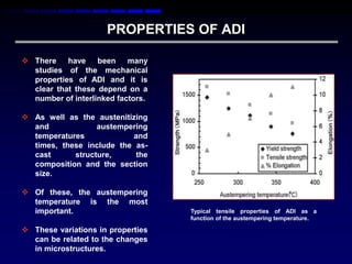
 Of these, the austempering
  temperature is the most
  important.                       Typical tensile properties of ADI as a
                                   function of the austempering temperature.

 These variations in properties
  can be related to the changes
  in microstructures.
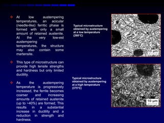
 At      low       austempering
  temperatures,     an    acicular
  (needle-like) ferritic phase is    Typical microstructure
  formed with only a small           obtained by austempering
                                     at a low temperature
  amount of retained austenite.
                                     (260C)
  At     the     very      low-est
  austempering
  temperatures, the structure
  may also contain some
  martensite.

 This type of microstructure can
  provide high tensile strengths
  and hardness but only limited
  ductility.
                                     Typical microstructure
                                     obtained by austempering
 As      the       austempering
                                     at a high temperature
  temperature is progressively       (375C)
  increased, the ferrite becomes
  coarser      and      increasing
  amounts of retained austenite
  (up to ~40%) are formed; This
  results   in    a    substantial
  increase in ductility and a
  reduction in strength and
  hardness.
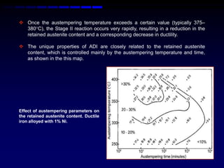
 Once the austempering temperature exceeds a certain value (typically 375–
  380C), the Stage II reaction occurs very rapidly, resulting in a reduction in the
  retained austenite content and a corresponding decrease in ductility.

 The unique properties of ADI are closely related to the retained austenite
  content, which is controlled mainly by the austempering temperature and time,
  as shown in the this map.


Effect of austempering parameters on
the retained austenite content. Ductile
iron alloyed with 1% Ni.
 It was recognized early in the development of ADI that specifications for specific
  grades were required by the buyers and suppliers of these materials.
 The most widely used specification is probably that developed by ASTM in 1990
  and subsequently updated in 2003. This is in both inch-poured (ASTM A897-03)
  and SI units (ASTM A897M-03).
 Dorn et al. have reviewed and compared the SAE and ISO Standards for ADI.
  There are also European and Japanese standards.


             Mechanical properties specified in ASTM A897M-03
           Tensile                                         Unnotched         Typical
                         Yield Strength    Elongation
Grade     Strength                                        Charpy Impact     Hardness
                             (MPa)            (%)
            (MPa)                                          Energy (J)        (BHN)

  1          900              650              9              100            269–341

  2         1050              750              7               80            302–375

  3         1200              850              4               60            341–444

  4         1400             1100              2               35            388–477

  5         1600             1300              1               20            402–512
SPECIFICATIONS
 ASTM: A897/A897M-03 Standard Specifications for Austempered
  Ductile Iron Castings.


 DORN, T. – KEOUGH, J.R. - SCHROEDER, T. – THOMA, A.: In:
  Proceedings 2003 Keith D. Millis Symposium on Ductile Iron. Hilton
  Head, AFS Inc. 2003, p. 33, FC03CD on CD ROM.


 BRITISH STANDARD EN1564:197. Founding – Austempered ductile
  cast iron.


 JAPANESE STANDARD JIS G 5503:1995. Austempered spheroidal
  graphite iron castings.
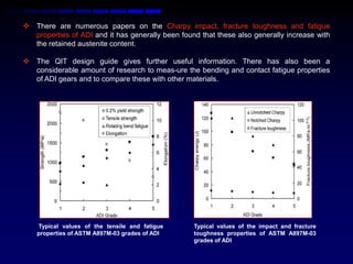
 There are numerous papers on the Charpy impact, fracture toughness and fatigue
  properties of ADI and it has generally been found that these also generally increase with
  the retained austenite content.

 The QIT design guide gives further useful information. There has also been a
  considerable amount of research to meas-ure the bending and contact fatigue properties
  of ADI gears and to compare these with other materials.


    Typical values of the tensile and fatigue     Typical values of the impact and fracture
    properties of ASTM A897M-03 grades of ADI     toughness properties of ASTM A897M-03
                                                  grades of ADI
 Good wear resistance is usually obtained in any material
  by ensuring a high hardness. Low austempering
  temperatures (235–250 C) produce hard ADI (~480–550
  BHN) and such grades would be selected when good wear
  resistance is the main requirement.

 As the austempering temperature increases, the
  hard-ness    decreases,    resulting in       more   wear.
  However, the softer grades of ADI (typically 280–320 BHN)
  contain large amounts of retained austenite and, this can
  work harden and/or transform to martensite when
  subjected to mechanical strain at the surface.
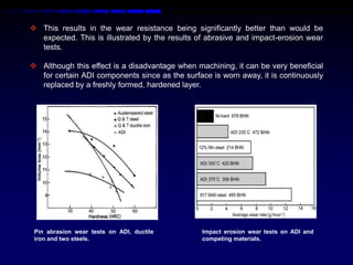
 This results in the wear resistance being significantly better than would be
  expected. This is illustrated by the results of abrasive and impact-erosion wear
  tests.

 Although this effect is a disadvantage when machining, it can be very beneficial
  for certain ADI components since as the surface is worn away, it is continuously
  replaced by a freshly formed, hardened layer.


 Pin abrasion wear tests on ADI, ductile        Impact erosion wear tests on ADI and
 iron and two steels.                           competing materials.
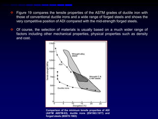
 Figure 19 compares the tensile properties of the ASTM grades of ductile iron with
  those of conventional ductile irons and a wide range of forged steels and shows the
  very competitive position of ADI compared with the mid-strength forged steels.

 Of course, the selection of materials is usually based on a much wider range of
  factors including other mechanical properties, physical properties such as density
  and cost.


                      Comparison of the minimum tensile properties of ADI
                      (ASTM A897M-03), ductile irons (EN1563:1977) and
                      forged steels (BS970:1983)
Moisture Embrittlement of ADI

 ADI can be embrittled when in contact with water and some other
  liquids such as oils and alcohol, as re-vealed by a drop of up to 30% in
  the tensile strength and up to 70% in the elongation.

 The phenomenon is also found in conventional ductile irons (apart
  from those with a ferritic matrix) but is not yet fully understood.

 It is claimed that the machinable ADIs developed recently are less
  susceptible.

 It has been proposed that it is linked to micro-cracking in the last-to-
  solidify zones at applied stress levels above the yield strength.
  However, since engineering components are normally designed so
  that they do not exceed the yield stress, it does not appear that this
  apparently alarming discovery is particularly significant.
Advantages of ADI

In brief, the advantages include:
    Lower tooling costs and improved tool life com-pared with steel forgings
    Lower raw material costs compared with steel or aluminum
    Lower energy costs compared with steel casting or forging
    Higher foundry yield (less feed metal, lower scrap) compared with steel or aluminum
     castings
    More component design freedom compared with forging, including the ability to
     make hollow shapes, to use reduced draft angles, and the ease of incorporating
     strengthening ribs and webs and lightening windows
    Improved ability to cast net shape components compared with steel
    Improved machinability in the as-cast condition
    Less distortion and risk of cracking during austempering compared with quenching
     and tempering treatments used for steels
    Lower density than steel
    Better noise and damping characteristics compared with steel
    Ability to work harden in service
Disadvantages of ADI
In contrast, the disadvantages include:
   Relatively poor machinability in the austempered condition which can lead to
    difficulties in inter-linking the foundry, machining and heat treatment operations.
   The high cost of austempering when done in small quantities
   The high capital cost of austempering plant means that it is often difficult to justify an
    in-house facility, although good sub-contract austempering facilities are now
    available in the US, Europe and Australia
   Lower elastic modulus than steels which may require the component design to be
    modified to increase the stiffness (although the increased flattening that takes place
    between mating surfaces usefully reduces the contact stresses)
   In common with most cast irons, ADI has poor weldability, thereby precluding the use
    of welding as part of the assembly process or for in-service repair
   The service temperature range is limited to about -40 to +200 C due to the risk of
    microstructural changes leading to a change in properties (although occasional
    excursions to 300-350 C are permitted)
   In spite of considerable publicity, the material is still largely unknown amongst
    many potential end-users.
A- AUTOMOTIVE APPLICATIONS OF ADI

 Since its introduction in the 1970‟s, ADI has been
  used in many wear resistant and engineering
  components in many different sectors including
  automotive, trucks, construction, earthmoving, a
  gricultural, rail-way and military.

 The worldwide production of ADI reached
  125,000 tons/year in 2000, and it has been
  predicted that ADI will grow to 200,000 tons/year
  in USA and 300,000 tons world-wide by 2010.
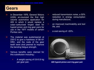
Gears
   In December 1976, General Motors            reduced transmission noise, a 50%
    (USA) an-nounced the first high              reduction in energy consumption
    volume automotive application for            during manufacture,
    ADI in which it would replace a
    case--carburized forged steel for           an improved machinability and tool
    hypoid pinion and ring gear pairs for        life, and
    use in the 1977 models of certain
    Pontiac cars.                               a cost saving of ~20%.

   The material was austempered at
    235C to give a hardness of 56–61
    HRC, and the roots of the gear
    teeth were shot peened to improve
    the bending fatigue strength.

   Various benefits were claimed for
    this substitution including :

          A weight saving of 0.6-0.9 kg
           per gear pair,                       ADI hypoid pinion and ring gear pair
 Similar substitutions were also made on other
  models, and over 5.5 million gear pairs had been used
  successfully by 1984 when there was a large-scale
  switch to front wheel drive cars.

 Related successful high volume (but not strictly
  automotive) applications of ADI include rear axle
  hyp-oid gears in Chinese trucks and timing gears for
  diesel engines produced by CDC (a joint US ven-ture
  between Cummins and Case). The latter gave cost
  savings of 30% over induction hardened or case--
  carburized forged steel gears.

 ADI bevel gears have been used successfully in a Ford
  Escort rally car to replace a case hardened forged steel.
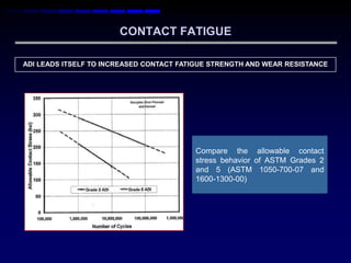
CONTACT FATIGUE

ADI LEADS ITSELF TO INCREASED CONTACT FATIGUE STRENGTH AND WEAR RESISTANCE


                                         Compare the allowable contact
                                         stress behavior of ASTM Grades 2
                                         and 5 (ASTM 1050-700-07 and
                                         1600-1300-00)
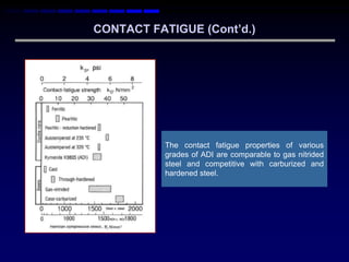
CONTACT FATIGUE (Cont‟d.)


           The contact fatigue properties of various
           grades of ADI are comparable to gas nitrided
           steel and competitive with carburized and
           hardened steel.
CONTACT FATIGUE (Cont‟d.)


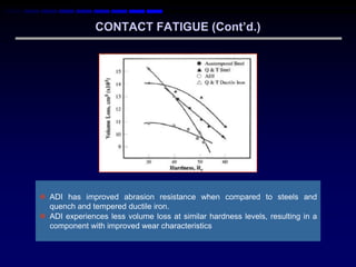
 ADI has improved abrasion resistance when compared to steels and
  quench and tempered ductile iron.
 ADI experiences less volume loss at similar hardness levels, resulting in a
  component with improved wear characteristics
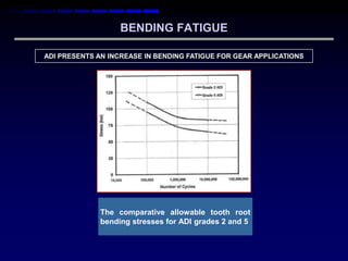
BENDING FATIGUE

ADI PRESENTS AN INCREASE IN BENDING FATIGUE FOR GEAR APPLICATIONS


              The comparative allowable tooth root
              bending stresses for ADI grades 2 and 5
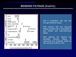
BENDING FATIGUE (Cont‟d.)


               ADI is competitive with cast and
                through-hardened steels.

               Shot peened ADI has improved
                fatigue strength that is comparable to
                gas nitrided and case-carburized
                steels.

               Shot peening can improve the
                allowable   bending     fatigue of
                carburized and hardened steels by
                30% and that of ADI by 75%
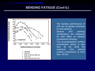
BENDING FATIGUE (Cont‟d.)


                The bending performance of
                 ADI can be greatly enhanced
                 by shot peening.
                Several      shot    peening
                 combinations are measured
                 for their effect on residual
                 compressive stresses.
                The as-austempered surface
                 compressive stress is less
                 than 30 ksi while the
                 maximum       shot    peened
                 surface compression is more
                 than 130 ksi.
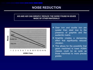
NOISE REDUCTION

AGI AND ADI CAN GREATLY REDUCE THE NOISE FOUND IN GEARS
                MADE OF OTHER MATERIALS


                                  Gear iron and ductile iron are
                                   quieter than steel due to the
                                   presence of graphite and the
                                   ausferritic matrix.
                                  Graphite creates a dampening
                                   effect that significantly reduces
                                   vibration.
                                  This allows for the possibility that
                                   gears machined to lower AGMA
                                   classes could be as quite as
                                   those machined to more precise
                                   grades
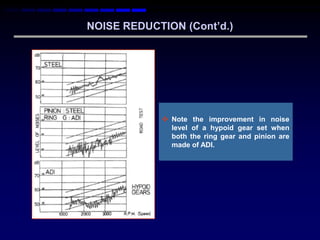
NOISE REDUCTION (Cont‟d.)


             Note the improvement in noise
              level of a hypoid gear set when
              both the ring gear and pinion are
              made of ADI.
 However, full scale produc-tion never
Crankshafts                                       materialized, apparently because the
                                                  much awaited Thunderbird Super
 Conventional ductile iron has competed
                                                  Coupe      was     running    be-hind
  successfully for many years with forged
                                                  schedule and over budget so the ADI
  steel for manufacturing crankshafts for
                                                  crankshaft was dropped in favor of
  petrol engines for passenger cars, but has
                                                  an imported steel forging.
  generally not had sufficient strength for
  more highly stressed diesel engine
  crankshafts.

 Twenty years ago there was great interest
  in an announcement by the Ford Motor
  Company (USA) that they had carried out
  extensive R&D on ADI crankshafts and
  that these would be replacing forged steel
  for diesel engine crankshafts in 1987.

 The ADI crankshafts were found to have
  double the fatigue strength of pearlitic
  ductile iron and to perform successfully at
  engine torques 10% higher than those
  specified for the forged steel crankshafts.
  The cost saving was estimated to be
  between $80–160 per part.
 Chrysler Corporation and most major automotive manufacturers, including
  GM, Ford, Nissan and Toyota have also undertaken extensive development on
  ADI crankshafts, apparently without leading to any subsequent industrial
  production.

 An extensive project carried out in the 1990‟s in the UK showed that ADI
  crankshafts thermally expand about 20% more than conventional ductile iron or
  steel crankshafts and this must be allowed for when designing the oil clearance
  tolerances in the bearing areas to prevent engine seizures.

 A successful low volume automotive ap-plication has been reported where ADI
  has been used to replace forged steel for the crankshaft in the 4 liter, 350 bhp in-
  line 6-cylinder en-gine in the TVR Tuscan Speed Six sports car manufactured in
  the UK.

 Advantages include a 4.5 kg weight saving (13%), lower manufacturing
  costs, and improved NVH (Noise-Vibration-Harshness) properties. The castings
  are rough machined, austempered, then finish machined and finally fillet rolled.

 This is apparently the only known production automotive application for ADI
  crankshafts.

 Tests    showed the ADI crankshafts to have a fatigue strength of 427
  MPa, compared with 324 MPa for a 800/2 pearlitic ductile iron and 400 MPa for a
  forged steel.
 In Iran, ADI was used to replace induction hardened forged steel for
  crankshafts for a 4 cylinder petrol engine and a single cylinder diesel
  engine. The latter is being produced for rice farm vehicles. The
  estimated cost saving is about 30%.

 Intermet has produced over a million austempered compressor
  crankshafts, but few details are available.

 European interest in ADI crankshafts continues. For example, an EC-
  funded CRAFT project called „Synergy‟ involves a number of partners
  and is developing hollow ADI diesel engine crankshafts using the lost
  foam casting process.

 The aims include reducing the weight, cost and manufacturing time.

 It is confidently expected that ADI crankshafts will be used in European
  cars within the next few years.
Connecting Rods

 A hollow ADI connecting rod weighing 400 g to
  replace a forged steel design weighing 600 g for an
  innovative 2 cylinder, 55 HP engine was developed.


 Extensive testing on prototype engines has given
  excellent results, but there is no evidence that these
  components have reached production.
Camshafts
 A wide variety of ferrous materials is used for cam-shafts
  depending on the valve train design. GM (USA) first used ADI
  camshafts for the L-4 engine in the 1980‟s.

 This camshaft was employed for the production life of the L-4
  engine and exceeded the requirement of 1,750 MPa contact
  stress at 10 million cycles with no pitting. It was produced for
  them by Intermet Corporation (USA).

 In 2000, it was reported that they had produced over 500,000
  selectively austempered camshafts, but is not known whether
  this was for more than one engine design.

 Mazda have used ADI camshafts for V6 petrol engines and have
  achieved cost savings and better pit-ting fatigue resistance than
  induction hardened forged steel or chilled cast iron. In 1991, it
  was reported that over 300,000 had been produced.
Timing Gear Support

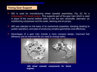
 ADI is used for manufacturing wheel cassette assemblies, Fig. 23, for a
  Volkswagen V10 diesel engine. This supports part of the gear train which is used
  in place of the normal toothed belts to link the twin camshafts, alternator, air
  conditioning compressor and the water, steering and oil pumps.

 ADI was selected on the basis of its mechanical properties, damping (leading to
  quieter operation), and ease of producing complex geometries cost effectively.

 Advantages of a gear train include a more compact design, improved fuel
  efficiency and an improved life (no need to change belts).


                   ADI wheel cassette components for diesel
                   engines.
Engine Mounts

 ADI has been used for engine mounts by Mazda, Japan
  to replace steel weldments with weight and cost savings.
  It has also been reported that ADI engine mounting
  brackets are used by GM, Ford and Mazda in the US.
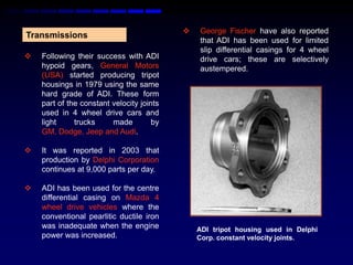
   George Fischer have also reported
Transmissions
                                               that ADI has been used for limited
                                               slip differential casings for 4 wheel
   Following their success with ADI           drive cars; these are selectively
    hypoid gears, General Motors               austempered.
    (USA) started producing tripot
    housings in 1979 using the same
    hard grade of ADI. These form
    part of the constant velocity joints
    used in 4 wheel drive cars and
    light     trucks     made         by
    GM, Dodge, Jeep and Audi.

   It was reported in 2003 that
    production by Delphi Corporation
    continues at 9,000 parts per day.

   ADI has been used for the centre
    differential casing on Mazda 4
    wheel drive vehicles where the
    conventional pearlitic ductile iron
    was inadequate when the engine             ADI tripot housing used in Delphi
    power was increased.                       Corp. constant velocity joints.
Suspension Components

 ADI has been used for numerous suspension components in heavy
  goods vehicles, but there has been little interest until recently in
  using ADI for automotive and light truck suspension components.

 Instead, the emphasis has been on converting ductile iron
  components to aluminum for weight savings at higher cost.

 However, with a changing emphasis to cost reduction, ADI may
  offer a cost and weight competitive alternative.

 An ADI upper control arm for a limited edition of the 1999 Ford
  Mustang Cobra sports car was developed.

 A Grade 1 ADI was selec-ted and shot peening was used to
  increase its fatigue strength. Competing materials were a ferritic
  ductile iron, a steel forging and an aluminum casting. It is not clear
  whether this component is still in production.
 The design and testing of a Grade 1 ADI lower control arm for the
  2003 heavy duty Dodge Ram pick-up truck as an alternative to the
  planned stamped steel weldment was proposed.

 This substitution would have led to 54% lower tooling costs and a
  small reduction in part weight (6%) and cost (2%).

 Unfortunately, errors during the development stage led to a delay in
  developing an acceptable ADI part and the opportunity for vehicle
  testing was missed.

 As a result, the stamping was chosen for the application, but it is
  considered that the experience gained would enable ADI to be
  considered for fu-ture applications and as a replacement for
  aluminum.

 The use of a Grade 1 ADI for a torsion bar adjuster for the Dodge
  Ram 4 4 pick-up truck was tried.
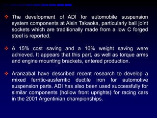
 The development of ADI for automobile suspension
  system components at Aisin Takaoka, particularly ball joint
  sockets which are traditionally made from a low C forged
  steel is reported.

 A 15% cost saving and a 10% weight saving were
  achieved. It appears that this part, as well as torque arms
  and engine mounting brackets, entered production.

 Aranzabal have described recent research to develop a
  mixed ferritic-ausferritic ductile iron for automotive
  suspension parts. ADI has also been used successfully for
  similar components (hollow front uprights) for racing cars
  in the 2001 Argentinian championships.
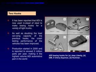
Two Hooks

   It has been reported that ADI is
    now used in-stead of steel to
    make towing hooks for a
    variety of light trucks.

   As well as doubling the load
    car-rying capacity of the
    previous hooks, the crash
    testing performance of the
    vehicles has been improved.

   Production started in 2000 and
    is reported to exceed 2 million
    parts per year, making it the
    highest volume ADI automotive      ADI towing hooks for (a) Jeep Liberty, (b)
                                       GM, © Chevy Equinox, (d) Hummer.
    part in the world
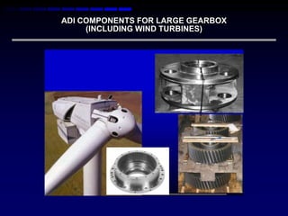
ADI COMPONENTS FOR LARGE GEARBOX
     (INCLUDING WIND TURBINES)
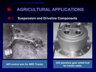
B-      AGRICULTURAL APPLICATIONS
 B.1.    Suspension and Driveline Components


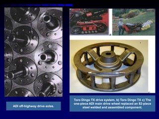
                                  ADI planetary gear wheel hub
ADI control arm for AWD Tractor
                                        for tractor axles.
b


                                                                          c


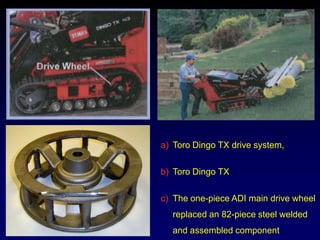
                               Toro Dingo TX drive system, b) Toro Dingo TX c) The
                               one-piece ADI main drive wheel replaced an 82-piece
ADI off-highway drive axles.         steel welded and assembled component.
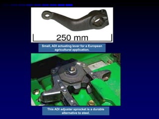
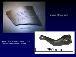
Small, ADI actuating lever for a European
        agricultural application.


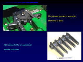
   This ADI adjuster sprocket is a durable
             alternative to steel.
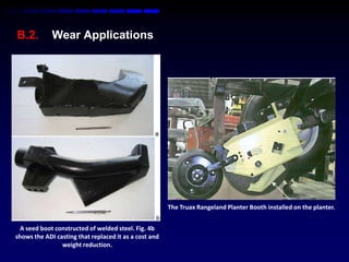
B.2.         Wear Applications


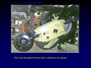
                                                       The Truax Rangeland Planter Booth installed on the planter.


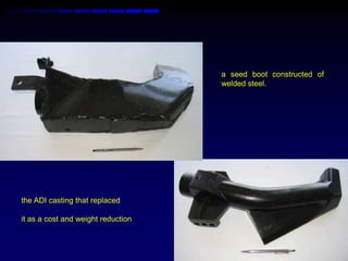
  A seed boot constructed of welded steel. Fig. 4b
shows the ADI casting that replaced it as a cost and
                weight reduction.
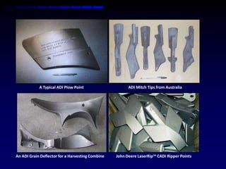
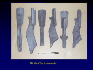
A Typical ADI Plow Point                    ADI Mitch Tips from Australia


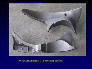
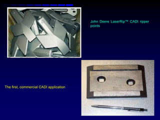
An ADI Grain Deflector for a Harvesting Combine   John Deere LaserRip™ CADI Ripper Points
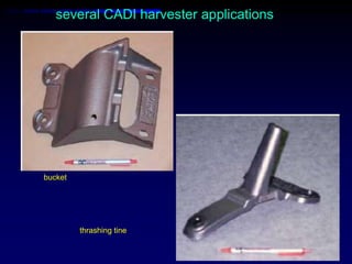
several CADI harvester applications


bucket


         thrashing tine
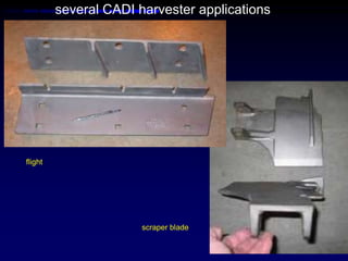
several CADI harvester applications


flight


                       scraper blade
The Truax Rangeland Planter Boot installed on the planter
a typical ADI plow point


Small, ADI actuating lever for a
European agricultural application
a) Toro Dingo TX drive system,

b) Toro Dingo TX

c) The one-piece ADI main drive wheel
  replaced an 82-piece steel welded
  and assembled component
ADI Mitch Tips from Australia
An ADI Grain Deflector for a harvesting combine.
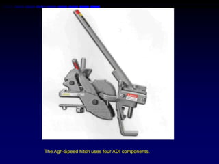
The Agri-Speed hitch uses four ADI components.
ADI adjuster sprocket is a durable

                                         alternative to steel


ADI rotating flail for an agricultural

mower-conditioner
John Deere LaserRip™ CADI ripper
                                         points


The first, commercial CADI application
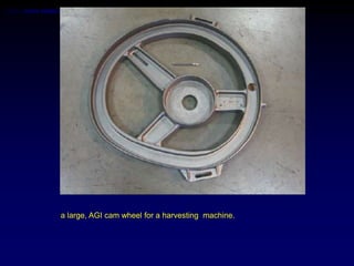
a large, AGI cam wheel for a harvesting machine.
a seed boot constructed of
                                    welded steel.


the ADI casting that replaced

it as a cost and weight reduction
CONCLUDING COMMENTS

 The available production statistics suggest that
  light vehicles represented 25% of applications
  for ADI in the US in 2008. Although this is quite
  respectable, it would seem to be a relatively
  small fraction of the potential market. With the
  exception of tow hooks and some medium
  volume components, it does not appear that
  there are any ADI automobile components being
  currently produced in high volume anywhere in
  the world. There are numerous reasons for
  this, including the following:
1. Investment
 A car manufacturer – or its foundry supplier(s) or a sub-
  contractor – will need to invest in dedic-ated heat
  treatment plant capable of austempering the large
  numbers of components required.

 Clearly, such capital expenditure requires a high level of
  confidence in the process and the product and a
  commitment by all parties involved.

 The most successful high volume automotive application
  was the rear axle hypoid gears for General Motors; in this
  case, the heat treatment plant was installed by GM.
2. Machining

The different machining techniques required for forged steel and ADI
components mean that it is not easy to transfer easily from one material to
another, particularly on a high volume machining line dedic-ated to the
production of one specific product, such as a crankshaft.

This was one of the motivations in the development of a machinable ADI.
A lack of experience of the high volume machining of ADI adds uncertainty
to the costs and production rates and the early experience of ADI exposed
some inconsistencies in the machinability.

However, these problems can be minimized by collaboration with a
knowledgeable foundry and heat treater.

There is growing confidence that the correct selection of machining tools
and conditions enables ADI with a tensile strength of 750-800 MPa to be
machined as easily as a pearlitic ductile iron with a tensile strength of 700
MPa.
3. Weight
There has been a sustained effort worldwide to use
lightweight materials in the automobile industry which has
eroded the market for cast irons due to their higher density.
ADI has suffered from being incorrectly conceived as a
„conventional‟ cast iron.

However, when the high strength of ADI is taken into account,
it is possible for it to compete successfully with lightweight
alloys.

This point has yet to be fully appreciated by many design
engineers and this is exacerbated by a decline in the number
of engineers who are trained in the production and use of
castings.
4. Cost
In the early days of ADI, the austempering fa-cilities
in many countries were inadequate and the heat
treatment cost was relatively high. However, a
recent cost breakdown has shown that, for medium
volume production in the US, the cost of ductile iron
castings is about half that of forged steel and even
when the costs of austempering and transport are
allowed for, ADI components typically give 20%
savings to the purchaser. This rises to ≥ 30% when
ADI replaces aluminum.
In summary, ADI is a family of cast
materials which offers high levels of
mechanical properties at a competitive
cost. They have already been used
successfully for high volume automotive
applications and it is confidently expected
that further applications will be developed
as their attributes become more widely
appreciated.
Austempered ductile iron production properties applications