Download to read offline
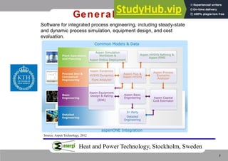
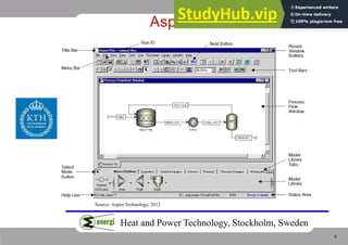
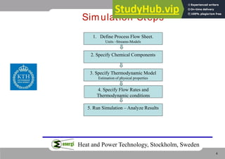
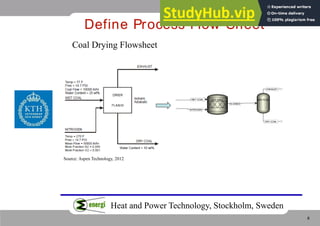
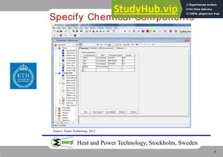
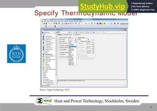
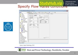
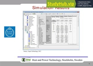
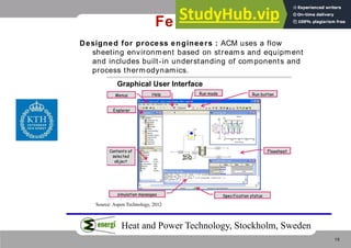
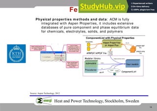
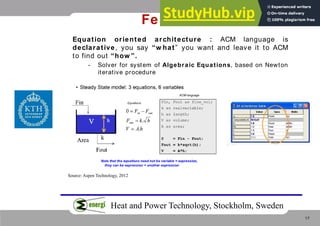
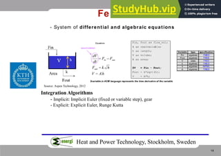
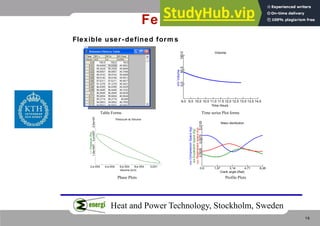
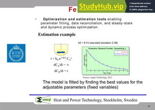
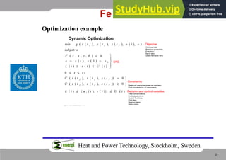
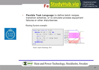
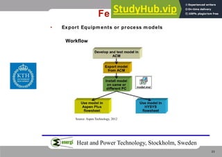
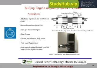
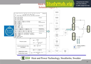


The document discusses Aspen Engineering Suite, a software package for integrated process engineering. It includes Aspen Plus and Aspen Custom Modeler. Aspen Plus is a process modeling tool that allows simulation of plant behaviors using mass and energy balances. It has rigorous equipment models and physical property methods. Aspen Custom Modeler allows creation of custom equipment models and process simulations. It uses a flowsheeting environment and includes optimization tools. An example is given of a Stirling engine model created in Aspen Custom Modeler that includes heat transfer and losses.


