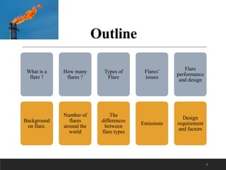
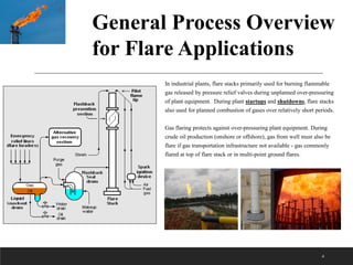
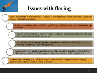
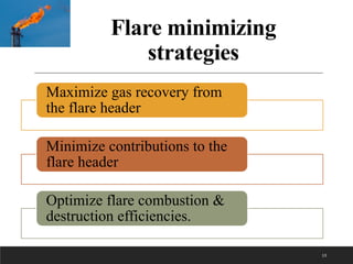
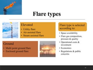
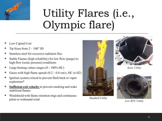
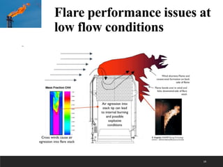
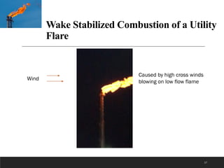
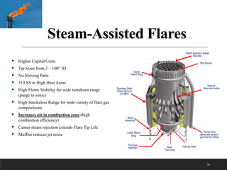
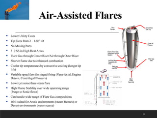
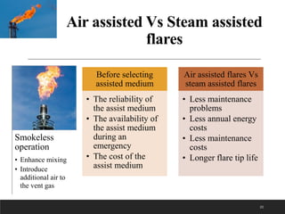
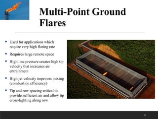
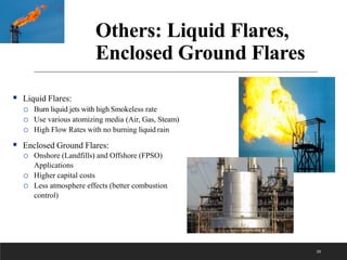
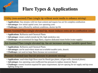
Flare
Technology &
Applications
Ahmed Maaroof
Chemical & Petroleum Engineering Department
Koya university
Ahmed.Maaroof@koyauniversity.Org
1
Outline
What is a
flare ?
Background
on flare.
How many
flares ?
Number of
flares
around the
world
Types of
Flare
The
differences
between
flare types
Flares’
issues
Emissions
Flare
performance
and design
Design
requirement
and factors
2
What is flare ?
3
• Flares are safety equipment used to burn high pressure gas from oil and gas production
fields or from chemical and petrochemical plants
• Flares combust unwanted flammable gases in an open environment to avoid deadly
fires and explosions.
• Industrial flaring has increased over the past several years due to increased oil
production.
• Flares operate cleanly at high flows but not at low flows.
• Proper flare design for low flow is critical.
• Environmental regulations dictate flare operating conditions and API recommends
flare design practices.
4
In industrial plants, flare stacks primarily used for burning flammable
gas released by pressure relief valves during unplanned over-pressuring
of plant equipment. During plant startups and shutdowns, flare stacks
also used for planned combustion of gases over relatively short periods.
Gas flaring protects against over-pressuring plant equipment. During
crude oil production (onshore or offshore), gas from well must also be
flare if gas transportation infrastructure not available - gas commonly
flared at top of flare stack or in multi-point ground flares.
General Process Overview
for Flare Applications
How Many Flares are
there?
5
Data Applications Include:
• Record amount of regional natural gas flaring
• Determine if flaring is chronic in region
(community)
• Track active gas-producing regions
• Identify source of noxious air emissions
• Minimize world-wide flaring by focusing on routine
flare operation regions
• Informing public health research on impacts of
flaring related to respiratory health
Flaring Maps
6
SkyTruth Flaring Maps; (a) Global, (b) Iraq
Top 30 Flaring Countries (2015-2019)
7
Years Gas Flaring (Billion m3/year) Oil Production (kb/d)
2016 148 92
2017 141 93
2018 145 95
2019 150 95
Gas Flaring volume (billion m3/year) and oil production (kb/d) in the world (2016-2019) (The World Bank, 2020).
Flaring Volume
(Million m3/year)
Flare Intensity
(m3 gas flared per barrel of oil produced)
Oil Production
(1,000 barrels per day)
2016 17,730 10.93 4,423
2017 17,843 10.98 4,538
2018 17,821 10.58 4,632
2019 17,914 10.38 4,779
Flaring volume, Flare intensity and oil production in Iraq (2016-2019) (The World Bank, 2020; British Petroleum, 2020).
8
Flaring volume & oil production
9
Each year, billions of cubic meters of flare gas is burned globally which generates a significant
amount of greenhouse gases.
Besides greenhouse gases, inefficient gas flaring can also produce toxic combustion by-
products.
Several flare designs have been developed to improve combustion efficiency including
flares using assistant media such as air
As a result of increased mixing and combustion, less black carbon is produced
resulting in improved smokeless operation
Understanding how ambient conditions and flare operating conditions effect flaring
efficiency is essential to finding ways to reduce their impact on the environment.
Combustion efficiency (CE) has been used as an indicator of flare performance. Highly
efficient flares operate with CE > 96.5 or greater.
Issues with flaring
(a) flaring with smoke, (b) faring without smoke
10
Gas Flaring in the
downstream process
Flare Emissions
11
Flare Emissions
12
Flare minimizing
strategies
Maximize gas recovery from
the flare header
Minimize contributions to the
flare header
Optimize flare combustion &
destruction efficiencies.
13
Flare types
Elevated
• Utility flare
• Air assisted flare
• Steam assisted flare
Ground
• Multi point ground flare
• Enclosed ground flare
14
Flare type is selected
according to:
• Space availability
• Flare gas composition,
pressure & quality
• Operational costs &
investment
• Economics
• Regulations & public
concerns
Utility Flares (i.e.,
Olympic flare)
15
 Low Capital Cost
 Tip Sizes from 2 – 100” ID
 Stainless steel for excessive radiation flux
 Stable Flames (high reliability) for low flow (purge) to
high flow (sonic pressure) conditions
 Large heating values ranges (0 - 100% HC)
 Gases with high flame speeds (0.2 – 0.8 cm/s; HC to H2)
 Ignition system critical to prevent flash back or vapor
explosions*
 Sufficient exit velocity to prevent smoking and wake
stabilized flames
 Windshield with flame retention rings and continuous
pilots to withstand wind Standard Utility
Sonic Utility
Low BTU Utility
Flare performance issues at
low flow conditions
16
Wake Stabilized Combustion of a Utility
Flare
17
Caused by high cross winds
blowing on low flow flame
Wind
Steam-Assisted Flares
18
 Higher Capital Costs
 Tip Sizes from 2 – 100” ID
 No Moving Parts
 310 SS in High Heat Areas
 High Flame Stability for wide turndown range
(purge to sonic)
 High Smokeless Range for wide variety of flare gas
compositions
 Increases air in combustion zone (high
combustion efficiency)
 Center steam injection extends Flare Tip Life
 Muffler reduces jet noise
Stainless Steel
Noise Shroud
(muffler)
Pilot Burner
Upper
Steam Ring
Pilot Gas
Manifold
Flame front
generator ignition
gas Inlet for Pilots
Mixer
Assembly
Velocity Seal
Main
Flare Gas
Steam Injection Spider
Nozzles
Lower Steam
Ring
Internal
Steam/air tubes
Example Steam Flare Tip
19
Looking down on steam flare tip
Ethylene steam flare without the steam
Lower steam tubes
Upper steam ring
Flare gas exits
between
steam tubes
Air-Assisted Flares
20
 Lower Utility Costs
 Tip Sizes from 2 – 120” ID
 No Moving Parts
 310 SS in High Heat Areas
 Flare Gas through Center Riser/Air through Outer Riser
 Shorter flame due to enhanced combustion
 Cooler tip temperatures by convective cooling (longer tip
life)
 Variable speed fans for staged firing (Vane-Axial, Engine
Driven, Centrifugal Blowers)
 Lower jet noise than steam flare
 High Flame Stability over wide operating range
(Purge to Sonic flows)
 Can handle wide range of Flare Gas compositions
 Well suited for Arctic environments (steam freezes) or
Desert environments (water scarce)
Main
Flare
Gas Inlet
Pilot
Burner
Outer Air
Plenum
Flame Front Gas
Generator Ignition
System
Pilot gas
manifold
Pilot Gas
inlet
Inner Flare
Gas Tip
Air/Gas Mixer
Assembly for
Pilot
Field Installed Air-Assisted
Flares (Vane-Axial Blowers)
21
Aramco; SaudiArabia
KOC; Kuwait Godley, Texas USA ExxonMobil; Venezuela
Air assisted Vs Steam assisted
flares
Smokeless
operation
• Enhance mixing
• Introduce
additional air to
the vent gas
22
Before selecting
assisted medium
• The reliability of
the assist medium
• The availability of
the assist medium
during an
emergency
• The cost of the
assist medium
Air assisted flares Vs
steam assisted flares
• Less maintenance
problems
• Less annual energy
costs
• Less maintenance
costs
• Longer flare tip life
Pressure-Assisted
Flares
23
 Single or Multi-stage configuration
 High Pressure operation
 Combustion occurs away from Tip (lower tip
temperature extends tip lifetime)
 Flare gas nozzles operate at sonic condition
 Can have entrained liquids
 Jet velocity entrains extra air that improves
combustion efficiency (higher smokeless rate)
 Can use with low pressure gas source
Pressure Assisted Flares –
Variable Exit Area
24
 High Pressure (>25 psig)
 Sonic jet nozzles / Spring Arm Design
 Varying exit area allows for higher
smokeless turndown rate with higher
MW flare gas
 Combustion occurs away from tip for
extended Tip lifetime
25
Multi-Point Ground
Flares
 Used for applications which
require very high flaring rate
 Requires large remote space
 High line pressure creates high tip
velocity that increases air
entrainment
 High jet velocity improves mixing
(combustion efficiency)
 Tip and row spacing critical to
provide sufficient air and allow tip
cross-lighting along row
Others: Liquid Flares,
Enclosed Ground Flares
26
 Liquid Flares:
o Burn liquid jets with high Smokeless rate
o Use various atomizing media (Air, Gas, Steam)
o High Flow Rates with no burning liquid rain
 Enclosed Ground Flares:
o Onshore (Landfills) and Offshore (FPSO)
Applications
o Higher capital costs
o Less atmosphere effects (better combustion
control)
Flare Types & Applications
Utility (non-assisted) Flare (single tip without assist media to enhance mixing)
• Applications: Gas streams with low heat content and require less air for complete combustion
• Advantages: low initial capital costs; low operating costs
• Challenges: more effected by ambient conditions, shorter tip life
Steam-Assisted Flare (single elevated tip, steam induces extra air in combustion zone)
• Applications: Refineries and Chemical Plants
• Advantages: steam cooled extends tip life, high smokeless rate
• Challenges: not economical for large flares, requires dedicated steam boiler (water supply)
Air-Assisted Flare (single elevated tip, fan air increases mixing, variable speed fans)
• Applications: Refineries and Chemical Plants
• Advantages: can be used where steam not available/useable (artic, desert)
• Challenges: not used on large flares because not economical
Pressure-Assisted (use line/air pressure to promote mixing)
• Applications: used when high flows must be flared (gas plants, oil/gas wells, chemical plants)
• Advantages: less operating costs (sufficient line pressure to replace steam/air flares)
• Challenges: remote location required for space requirement, tip/row spacing for air supply and tip cross
lighting along row
27
Flare performance
28
Table 1: factors affecting flare combustion efficiency
Over steaming & aeration
Heating Value
Crosswind & Vent Gas velocity
flare flame lift-off
Dilution
Crosswind
effect (CFD)
29
0 kg/m2.s
5 kg/m2.s
10 kg/m2.s
10 kg/m2.s
15 kg/m2.s
Ethylene
Ethylene
Ethylene
Propylene
Propylene
Flame stability
Flame stability
flame speed
flammability limits
ignition temperature
30
Flare system & Design
factors
Flare system
• Collection piping in the
unit
• A flare line to the site
• A knockout drum
• A liquid seal
• A flare stack with flare tip
• An assist system
• A fuel gas system for pilots
and ignitors
• Controls & instrumentation.
Design factors
• Flow rate
• Gas composition
• Gas temperature
• Gas pressure
• Utility cost and availability
• Environmental
requirements
• Safety requirements
• Social requirements
31
Design requirements
Design requirements
• Flares have to be at least as high as any platform within 150 m
horizontally, and in no case less than 15 m high.
• The base of flares should be installed at least 60 m away from any
source of flammable hydrocarbons for example floating roof or
separators.
• Flare spacing & elevation should be such that permissible
radiation heat intensities for personnel at grade will not exceed
under condition of maximum heat release, where it should be
installed in locations where the maximum heat intensity at ground
level is 1.6 kW/m2 in any property line.
• The minimum distance from the flare stack base to nearby
property line should be 60 m.
32
33

Flare technology

  • 1.
    Flare Technology & Applications Ahmed Maaroof Chemical& Petroleum Engineering Department Koya university Ahmed.Maaroof@koyauniversity.Org 1
  • 2.
    Outline What is a flare? Background on flare. How many flares ? Number of flares around the world Types of Flare The differences between flare types Flares’ issues Emissions Flare performance and design Design requirement and factors 2
  • 3.
    What is flare? 3 • Flares are safety equipment used to burn high pressure gas from oil and gas production fields or from chemical and petrochemical plants • Flares combust unwanted flammable gases in an open environment to avoid deadly fires and explosions. • Industrial flaring has increased over the past several years due to increased oil production. • Flares operate cleanly at high flows but not at low flows. • Proper flare design for low flow is critical. • Environmental regulations dictate flare operating conditions and API recommends flare design practices.
  • 4.
    4 In industrial plants,flare stacks primarily used for burning flammable gas released by pressure relief valves during unplanned over-pressuring of plant equipment. During plant startups and shutdowns, flare stacks also used for planned combustion of gases over relatively short periods. Gas flaring protects against over-pressuring plant equipment. During crude oil production (onshore or offshore), gas from well must also be flare if gas transportation infrastructure not available - gas commonly flared at top of flare stack or in multi-point ground flares. General Process Overview for Flare Applications
  • 5.
    How Many Flaresare there? 5 Data Applications Include: • Record amount of regional natural gas flaring • Determine if flaring is chronic in region (community) • Track active gas-producing regions • Identify source of noxious air emissions • Minimize world-wide flaring by focusing on routine flare operation regions • Informing public health research on impacts of flaring related to respiratory health
  • 6.
    Flaring Maps 6 SkyTruth FlaringMaps; (a) Global, (b) Iraq
  • 7.
    Top 30 FlaringCountries (2015-2019) 7
  • 8.
    Years Gas Flaring(Billion m3/year) Oil Production (kb/d) 2016 148 92 2017 141 93 2018 145 95 2019 150 95 Gas Flaring volume (billion m3/year) and oil production (kb/d) in the world (2016-2019) (The World Bank, 2020). Flaring Volume (Million m3/year) Flare Intensity (m3 gas flared per barrel of oil produced) Oil Production (1,000 barrels per day) 2016 17,730 10.93 4,423 2017 17,843 10.98 4,538 2018 17,821 10.58 4,632 2019 17,914 10.38 4,779 Flaring volume, Flare intensity and oil production in Iraq (2016-2019) (The World Bank, 2020; British Petroleum, 2020). 8 Flaring volume & oil production
  • 9.
    9 Each year, billionsof cubic meters of flare gas is burned globally which generates a significant amount of greenhouse gases. Besides greenhouse gases, inefficient gas flaring can also produce toxic combustion by- products. Several flare designs have been developed to improve combustion efficiency including flares using assistant media such as air As a result of increased mixing and combustion, less black carbon is produced resulting in improved smokeless operation Understanding how ambient conditions and flare operating conditions effect flaring efficiency is essential to finding ways to reduce their impact on the environment. Combustion efficiency (CE) has been used as an indicator of flare performance. Highly efficient flares operate with CE > 96.5 or greater. Issues with flaring
  • 10.
    (a) flaring withsmoke, (b) faring without smoke 10 Gas Flaring in the downstream process
  • 11.
  • 12.
  • 13.
    Flare minimizing strategies Maximize gasrecovery from the flare header Minimize contributions to the flare header Optimize flare combustion & destruction efficiencies. 13
  • 14.
    Flare types Elevated • Utilityflare • Air assisted flare • Steam assisted flare Ground • Multi point ground flare • Enclosed ground flare 14 Flare type is selected according to: • Space availability • Flare gas composition, pressure & quality • Operational costs & investment • Economics • Regulations & public concerns
  • 15.
    Utility Flares (i.e., Olympicflare) 15  Low Capital Cost  Tip Sizes from 2 – 100” ID  Stainless steel for excessive radiation flux  Stable Flames (high reliability) for low flow (purge) to high flow (sonic pressure) conditions  Large heating values ranges (0 - 100% HC)  Gases with high flame speeds (0.2 – 0.8 cm/s; HC to H2)  Ignition system critical to prevent flash back or vapor explosions*  Sufficient exit velocity to prevent smoking and wake stabilized flames  Windshield with flame retention rings and continuous pilots to withstand wind Standard Utility Sonic Utility Low BTU Utility
  • 16.
    Flare performance issuesat low flow conditions 16
  • 17.
    Wake Stabilized Combustionof a Utility Flare 17 Caused by high cross winds blowing on low flow flame Wind
  • 18.
    Steam-Assisted Flares 18  HigherCapital Costs  Tip Sizes from 2 – 100” ID  No Moving Parts  310 SS in High Heat Areas  High Flame Stability for wide turndown range (purge to sonic)  High Smokeless Range for wide variety of flare gas compositions  Increases air in combustion zone (high combustion efficiency)  Center steam injection extends Flare Tip Life  Muffler reduces jet noise Stainless Steel Noise Shroud (muffler) Pilot Burner Upper Steam Ring Pilot Gas Manifold Flame front generator ignition gas Inlet for Pilots Mixer Assembly Velocity Seal Main Flare Gas Steam Injection Spider Nozzles Lower Steam Ring Internal Steam/air tubes
  • 19.
    Example Steam FlareTip 19 Looking down on steam flare tip Ethylene steam flare without the steam Lower steam tubes Upper steam ring Flare gas exits between steam tubes
  • 20.
    Air-Assisted Flares 20  LowerUtility Costs  Tip Sizes from 2 – 120” ID  No Moving Parts  310 SS in High Heat Areas  Flare Gas through Center Riser/Air through Outer Riser  Shorter flame due to enhanced combustion  Cooler tip temperatures by convective cooling (longer tip life)  Variable speed fans for staged firing (Vane-Axial, Engine Driven, Centrifugal Blowers)  Lower jet noise than steam flare  High Flame Stability over wide operating range (Purge to Sonic flows)  Can handle wide range of Flare Gas compositions  Well suited for Arctic environments (steam freezes) or Desert environments (water scarce) Main Flare Gas Inlet Pilot Burner Outer Air Plenum Flame Front Gas Generator Ignition System Pilot gas manifold Pilot Gas inlet Inner Flare Gas Tip Air/Gas Mixer Assembly for Pilot
  • 21.
    Field Installed Air-Assisted Flares(Vane-Axial Blowers) 21 Aramco; SaudiArabia KOC; Kuwait Godley, Texas USA ExxonMobil; Venezuela
  • 22.
    Air assisted VsSteam assisted flares Smokeless operation • Enhance mixing • Introduce additional air to the vent gas 22 Before selecting assisted medium • The reliability of the assist medium • The availability of the assist medium during an emergency • The cost of the assist medium Air assisted flares Vs steam assisted flares • Less maintenance problems • Less annual energy costs • Less maintenance costs • Longer flare tip life
  • 23.
    Pressure-Assisted Flares 23  Single orMulti-stage configuration  High Pressure operation  Combustion occurs away from Tip (lower tip temperature extends tip lifetime)  Flare gas nozzles operate at sonic condition  Can have entrained liquids  Jet velocity entrains extra air that improves combustion efficiency (higher smokeless rate)  Can use with low pressure gas source
  • 24.
    Pressure Assisted Flares– Variable Exit Area 24  High Pressure (>25 psig)  Sonic jet nozzles / Spring Arm Design  Varying exit area allows for higher smokeless turndown rate with higher MW flare gas  Combustion occurs away from tip for extended Tip lifetime
  • 25.
    25 Multi-Point Ground Flares  Usedfor applications which require very high flaring rate  Requires large remote space  High line pressure creates high tip velocity that increases air entrainment  High jet velocity improves mixing (combustion efficiency)  Tip and row spacing critical to provide sufficient air and allow tip cross-lighting along row
  • 26.
    Others: Liquid Flares, EnclosedGround Flares 26  Liquid Flares: o Burn liquid jets with high Smokeless rate o Use various atomizing media (Air, Gas, Steam) o High Flow Rates with no burning liquid rain  Enclosed Ground Flares: o Onshore (Landfills) and Offshore (FPSO) Applications o Higher capital costs o Less atmosphere effects (better combustion control)
  • 27.
    Flare Types &Applications Utility (non-assisted) Flare (single tip without assist media to enhance mixing) • Applications: Gas streams with low heat content and require less air for complete combustion • Advantages: low initial capital costs; low operating costs • Challenges: more effected by ambient conditions, shorter tip life Steam-Assisted Flare (single elevated tip, steam induces extra air in combustion zone) • Applications: Refineries and Chemical Plants • Advantages: steam cooled extends tip life, high smokeless rate • Challenges: not economical for large flares, requires dedicated steam boiler (water supply) Air-Assisted Flare (single elevated tip, fan air increases mixing, variable speed fans) • Applications: Refineries and Chemical Plants • Advantages: can be used where steam not available/useable (artic, desert) • Challenges: not used on large flares because not economical Pressure-Assisted (use line/air pressure to promote mixing) • Applications: used when high flows must be flared (gas plants, oil/gas wells, chemical plants) • Advantages: less operating costs (sufficient line pressure to replace steam/air flares) • Challenges: remote location required for space requirement, tip/row spacing for air supply and tip cross lighting along row 27
  • 28.
    Flare performance 28 Table 1:factors affecting flare combustion efficiency Over steaming & aeration Heating Value Crosswind & Vent Gas velocity flare flame lift-off Dilution
  • 29.
    Crosswind effect (CFD) 29 0 kg/m2.s 5kg/m2.s 10 kg/m2.s 10 kg/m2.s 15 kg/m2.s Ethylene Ethylene Ethylene Propylene Propylene
  • 30.
    Flame stability Flame stability flamespeed flammability limits ignition temperature 30
  • 31.
    Flare system &Design factors Flare system • Collection piping in the unit • A flare line to the site • A knockout drum • A liquid seal • A flare stack with flare tip • An assist system • A fuel gas system for pilots and ignitors • Controls & instrumentation. Design factors • Flow rate • Gas composition • Gas temperature • Gas pressure • Utility cost and availability • Environmental requirements • Safety requirements • Social requirements 31
  • 32.
    Design requirements Design requirements •Flares have to be at least as high as any platform within 150 m horizontally, and in no case less than 15 m high. • The base of flares should be installed at least 60 m away from any source of flammable hydrocarbons for example floating roof or separators. • Flare spacing & elevation should be such that permissible radiation heat intensities for personnel at grade will not exceed under condition of maximum heat release, where it should be installed in locations where the maximum heat intensity at ground level is 1.6 kW/m2 in any property line. • The minimum distance from the flare stack base to nearby property line should be 60 m. 32
  • 33.