This paper deals with the problem of robust jointly state and fault estimation (actuator and sensor) observer design for discrete-time Descriptor-Linear Parameter Varying (D-LPV) with unmeasurable gain scheduling. The proposed approach is based on the H ∞ synthesis applied to the state estimation error. Sufficient conditions are given by a set of Linear Matrix
Inequalities (LMIs), which guarantee robustness to disturbances/noise and to the error given by the unmeasurable gain scheduling functions. Thus, the main contribution is to develop a conceptually simple integrated procedure to estimate states, sensor or actuator faults. In order to illustrate the methodology, simulations based on a realistic model of binary distillation column are considered.
Selection of amine solvents for CO2 capture from natural gas power plant - presentation by Jiafei Zhang of Imperial College London at the UKCCSRC Natural Gas CCS Network Meeting at GHGT-12, Austin, Texas, October 2014
Introduction to free and open source Chemical Process Simulators - (DWSIM & C...CAChemE
Learn the fundamentals of any chemical process simulator software by means of free and open source software as an alternative to Aspen, Aspen HYSYS, etc. We will be using DWSIM (open source and free) and COCO Simulator (freeware) for this course. Material is licensed under CC BY-NC-SA 3.0.
You can find more learning material for chemical engineers in http://CAChemE.org
TAGs: chemical , process , simulator , engineering , coco , dwsim , hysys , aspen , prosim , theory, software, free, open, source, flowsheet, course
Simulation of Chemical Rectors - Introduction to chemical process simulators ...CAChemE
Learn the fundamentals of any chemical process simulator software by means of free and open source software as an alternative to Aspen, Aspen HYSYS, etc. We will be using DWSIM (open source and free) and COCO Simulator (freeware) for this course. Material is licensed under CC BY-NC-SA 3.0.
You can find more learning material for chemical engineers in http://CAChemE.org
Aspen Plus basic course for Engineers.
Introduction to Process Modeling/Simulation Software.
INDEX:
Course Objectives
Introduction to Aspen Plus
User Interface & Getting Help
Physical Properties
Introduction to Flowsheet
Unit Operation Models
Reporting Results
Case Studies I, II and III
Case Study IV
Conclusion
ECRIN SAPHIR TUTORIAL Dr. P. Ghahri Prepared by.docxtidwellveronique
ECRIN SAPHIR TUTORIAL
Dr. P. Ghahri
Prepared by: Amir Golparvar
[email protected]
Ecrin Saphir Tutorial
Initialization
This turotial is an introduction to the basic features of Saphir. It is assumed that you have installed Ecrin
workstation or Saphir stand alone to follow this session. The session can be followed in all levels of Saphir
except the Saphir reader.
The session will use the following files provided in the tutorial directory: SapGS01.rat, the rate file and
SapGS01.pre, the pressure file. The extension to the files is not important here as any ASCII file can be
loaded by the application.
Click on new project icon directly from toolbar.
This opens in succession two dialogs:
Ecrin Saphir Tutorial
This dialog allows you to choose the test type, reference fluid type, the available fluid rates, net drained
thickness, well radius and average porosity. Set the reference time to Dec 4, 1999 at 00:06:45 hours. Keep
all other parameters as the suggested default.
Click
You input the PVT characteristics; formation volumes factor, the fluid viscosity and the system
compressibility. Keep all values at their suggested defaults.
Click to create the new project. The Saphir main screen is displayed.
Ecrin Saphir Tutorial
The main screen is opened with the 'Interpretation' page active. This page (or panel) contains six icons
and by clicking consecutively on the icons from top to bottom, executing the dialogs and instructions, you
will follow exactly the default path of the basic workflow used in pressure transient analysis.
Loading Data
Click . This will initialize the load sequence which is normally a sequence of two dialogs. Specify
an ASCII file in the 'Define Data Source' dialog and click on to browse to the file SapGS01.rat in the
tutorial directory. A preview of the file will be shown in the dialog as illustrated in Figure below.
Ecrin Saphir Tutorial
Click to go to the Data Format dialog. Saphir has recognized the file as valid and has
automatically assigned the first column as 'Decimal Time' and the second as 'Oil Rate'. This is known as
'free format'. The units are correct so no need to change the formatting proposed by Saphir. See Figure
Below.
Ecrin Saphir Tutorial
Click on to load the flow rate file. A history plot with the loaded flowrate file in steps is
displayed. Double click in the title bar of the plot to maximize it and display the scales.
A click on the time button in the time scale will change the scale to real time (ToD) as
defined with the reference date and time at startup. Minimize the plot.
Ecrin Saphir Tutorial
Loading Pressure Data
Click on the icon . This will initialize the load process. Specify an ASCII file in the 'Define Data
Source' dialog and click on to browse to the file SapGS01.pre in the tutorial directory. A preview of the file
will be shown in th.
Fundamental of Information Technology - UNIT 6Shipra Swati
Computer Programming and Languages : algorithm, Flow Chart, Pseudo Code, Program
Control Structures, Programming Languages, Generation of Programming Languages and
etc.
Diseno en ingenieria mecanica de Shigley - 8th ---HDes
descarga el contenido completo de aqui http://paralafakyoumecanismos.blogspot.com.ar/2014/08/libro-para-mecanismos-y-elementos-de.html
ENGR 131 Elementary Computer ProgrammingTeam IN – InstructorTanaMaeskm
ENGR 131: Elementary Computer Programming
Team IN – Instructor
Midterm Exam
INSTRUCTIONS
Complete the exercises below and upload them to Canvas as a single MATLAB script file (.m) using the naming convention “ENGR131_21F_Midterm_abc123.m”, replacing abc123 with your Case ID, and ## with the two- digit lab number.
For example, if Dr. Williams were submitting this test, it would be ENGR131_21F_Midterm_mrw8.m For your script, please perform the following:
1. Separate each question into separate, runnable sections using the “%%” comment notation.
2. You may use the code and notes from class, the textbook, and MATLAB’s documentation.
3. Use comments as appropriate to indicate your thoughts and how your code works (or is supposed to work). This is 10 points (10%) of your grade.
QUESTIONS
There are 3 questions for this exam.
(
ENGR 131 21F-IN-060-101-A (Midterm Instructions)
) (
9/23/2021
) (
Page
1
of 5
)
1. SOLVING SYSTEMS OF EQUATIONS (20 PTS)
There’s a chill in the air and Fall is here. There are so many neat things that make Fall so special, as shown in Figure 1. Solve for the value of each Fall icon using a systems of equations approach. DO NOT use the symbolic solver (you will receive 0 points if you do). You will know you have the right answer as the correct values in the correct order, when rounded, transposed, and converted to characters, should spell out a recognizable word. Return your solution values to the Command Window.
580
401
378
740
Key:
474
531
Apple Football Grapes Leaves Pumpkin Tree
Fig. 1. The themes of Fall
2. COMPUTING VOLUMES (20 PTS)
A particular conical red cup is often found at many social gatherings in college filled with apple cider. The dimensions of this cup can be found in Figure 2a. Based on these dimensions, use Matlab to determine the locations at which you would place markings for 5, 9, and 16 oz. of fluid such that the volume at each height computed would match each target volume. Use the method of computing the volume of a revolved solid using a step size of 0.15 in. and iterating the volume calculation (your choice of method) with an increasing height until the correct volume is reached. Report these computed heights to the Command Window and replicate Figure 2b.
5
4.5
4
3.5
(
Fluid Depth (in)
)3
2.5
2
1.5
1
0.5
Cup Profile With Markings for 5, 9, and 16 oz.
0
(a) (b)
(
Cup 3
oz
8
oz
14.5 oz
)0 0.5 1
1.5 2 2.5 3 3.5 4 4.5 5
Cup Radius (in)
Figure 2. Dimensions of popular party cup (a), and profile of cup with the height of each target volume shown (b).
3. CELL SIMULATOR (50 PTS)
Program a basic simulator that uses a few simple rules to govern whether cells in a “dish” persist or die and when new living cells appear. At each step in your simulation it should show those cells that are going to die and those that will become live with red ‘x’s and green stars respectively as shown in Figure 3b before ending the step wi ...
Getting Started with Chemcad
Creating flowsheets and running simulations is fast and easy with CHEMCAD, and the program is highly customizable to fit your needs and the way you work.
Before we start , should you know the basic procedure for creating a simulation that can be broken down into the following common steps:
1-Start new simulation
2-Select engineering units for the simulation.
3-Create a flow sheet
4-Select chemical components for the process.
5-Select K‐value and enthalpy options for the process.
6-Define the feed streams used in the process.
7-Enter specifications for the unit operations.
8-Run the simulation.
Let start with a simple example to show how you can applied previous procedure.
Example 1
A flash chamber operating 80oC(176oF)and 500kPa (72.5 psia)is separating 1000 kg/hr (2204 lb/hr) of a feed that is 10 mol%Ethane, 5%Propane, 15% n-Butane, 10% n-Pentane,12% iso-Pentane, 8% n-Hexane, 30%Heptane and 10%Nonane. What are the product compositions and flow rates? Feed conditions are the same as that of the flash chamber.
Solution Methodology
Step 1: After you Start up Chemcad , start new simulation, how?
Select File>>Save as, then name your simulation Flash Chamber. See pictures below.
Step 2: Now select engineering units that you will use for your simulation.
Select Format>>Engineering Unit>> Select default setting in English units.
Step3: Creat flowsheet
- First you need to select the piece(s) of equipment you desire, from All UnitOps tap select Feed arraw, two prodcut arraws and Flash #1.
Then select Stream to conect Flash with in and outputs arraws,after connecting press Ecs. -
Step 4: select chemical components for the process and here we have (Ethane, Propane, n-Butane, n-Pentane, iso-Pentane, n-Hexane, Heptane and Nonane), from toolbar select ,or select Thermophysical>>Select components..
from available component select desired components and then press
Step 5: Select K‐value and enthalpy options for the process, after selecting the desired components thermodynamic wizard window open to let the user enter pressure/temperature rang for the process or you can use the default rang, these input let the program choose the suitable thermodynamic models.
After press OK the program choose thermodynamic process for your process.
Press OK, and the program open a thermodynamic setting ,if you accept the default thermodynamic model by program press OK, if not change it, from global K values option select the thermodynamic model that you want, here want to chang SRK to Peng-Robinson.
Step 6: Define the feed streams, by double click on stream 1 entering to the flash separator, then enter the name to the stream optionally, specify temperature and pressure and the enthalpy and vapor fraction calculated automatically or specify pressure and vapor fraction and the enthalpy and temperature calculated and so on.
Similar to Modeling separation systems_with_aspen_plus (20)
Attending a job Interview for B1 and B2 Englsih learnersErika906060
It is a sample of an interview for a business english class for pre-intermediate and intermediate english students with emphasis on the speking ability.
Business Valuation Principles for EntrepreneursBen Wann
This insightful presentation is designed to equip entrepreneurs with the essential knowledge and tools needed to accurately value their businesses. Understanding business valuation is crucial for making informed decisions, whether you're seeking investment, planning to sell, or simply want to gauge your company's worth.
Enterprise Excellence is Inclusive Excellence.pdfKaiNexus
Enterprise excellence and inclusive excellence are closely linked, and real-world challenges have shown that both are essential to the success of any organization. To achieve enterprise excellence, organizations must focus on improving their operations and processes while creating an inclusive environment that engages everyone. In this interactive session, the facilitator will highlight commonly established business practices and how they limit our ability to engage everyone every day. More importantly, though, participants will likely gain increased awareness of what we can do differently to maximize enterprise excellence through deliberate inclusion.
What is Enterprise Excellence?
Enterprise Excellence is a holistic approach that's aimed at achieving world-class performance across all aspects of the organization.
What might I learn?
A way to engage all in creating Inclusive Excellence. Lessons from the US military and their parallels to the story of Harry Potter. How belt systems and CI teams can destroy inclusive practices. How leadership language invites people to the party. There are three things leaders can do to engage everyone every day: maximizing psychological safety to create environments where folks learn, contribute, and challenge the status quo.
Who might benefit? Anyone and everyone leading folks from the shop floor to top floor.
Dr. William Harvey is a seasoned Operations Leader with extensive experience in chemical processing, manufacturing, and operations management. At Michelman, he currently oversees multiple sites, leading teams in strategic planning and coaching/practicing continuous improvement. William is set to start his eighth year of teaching at the University of Cincinnati where he teaches marketing, finance, and management. William holds various certifications in change management, quality, leadership, operational excellence, team building, and DiSC, among others.
Buy Verified PayPal Account | Buy Google 5 Star Reviewsusawebmarket
Buy Verified PayPal Account
Looking to buy verified PayPal accounts? Discover 7 expert tips for safely purchasing a verified PayPal account in 2024. Ensure security and reliability for your transactions.
PayPal Services Features-
🟢 Email Access
🟢 Bank Added
🟢 Card Verified
🟢 Full SSN Provided
🟢 Phone Number Access
🟢 Driving License Copy
🟢 Fasted Delivery
Client Satisfaction is Our First priority. Our services is very appropriate to buy. We assume that the first-rate way to purchase our offerings is to order on the website. If you have any worry in our cooperation usually You can order us on Skype or Telegram.
24/7 Hours Reply/Please Contact
usawebmarketEmail: support@usawebmarket.com
Skype: usawebmarket
Telegram: @usawebmarket
WhatsApp: +1(218) 203-5951
USA WEB MARKET is the Best Verified PayPal, Payoneer, Cash App, Skrill, Neteller, Stripe Account and SEO, SMM Service provider.100%Satisfection granted.100% replacement Granted.
RMD24 | Debunking the non-endemic revenue myth Marvin Vacquier Droop | First ...BBPMedia1
Marvin neemt je in deze presentatie mee in de voordelen van non-endemic advertising op retail media netwerken. Hij brengt ook de uitdagingen in beeld die de markt op dit moment heeft op het gebied van retail media voor niet-leveranciers.
Retail media wordt gezien als het nieuwe advertising-medium en ook mediabureaus richten massaal retail media-afdelingen op. Merken die niet in de betreffende winkel liggen staan ook nog niet in de rij om op de retail media netwerken te adverteren. Marvin belicht de uitdagingen die er zijn om echt aansluiting te vinden op die markt van non-endemic advertising.
LA HUG - Video Testimonials with Chynna Morgan - June 2024Lital Barkan
Have you ever heard that user-generated content or video testimonials can take your brand to the next level? We will explore how you can effectively use video testimonials to leverage and boost your sales, content strategy, and increase your CRM data.🤯
We will dig deeper into:
1. How to capture video testimonials that convert from your audience 🎥
2. How to leverage your testimonials to boost your sales 💲
3. How you can capture more CRM data to understand your audience better through video testimonials. 📊
Kseniya Leshchenko: Shared development support service model as the way to ma...Lviv Startup Club
Kseniya Leshchenko: Shared development support service model as the way to make small projects with small budgets profitable for the company (UA)
Kyiv PMDay 2024 Summer
Website – www.pmday.org
Youtube – https://www.youtube.com/startuplviv
FB – https://www.facebook.com/pmdayconference
Falcon stands out as a top-tier P2P Invoice Discounting platform in India, bridging esteemed blue-chip companies and eager investors. Our goal is to transform the investment landscape in India by establishing a comprehensive destination for borrowers and investors with diverse profiles and needs, all while minimizing risk. What sets Falcon apart is the elimination of intermediaries such as commercial banks and depository institutions, allowing investors to enjoy higher yields.
Tata Group Dials Taiwan for Its Chipmaking Ambition in Gujarat’s DholeraAvirahi City Dholera
The Tata Group, a titan of Indian industry, is making waves with its advanced talks with Taiwanese chipmakers Powerchip Semiconductor Manufacturing Corporation (PSMC) and UMC Group. The goal? Establishing a cutting-edge semiconductor fabrication unit (fab) in Dholera, Gujarat. This isn’t just any project; it’s a potential game changer for India’s chipmaking aspirations and a boon for investors seeking promising residential projects in dholera sir.
Visit : https://www.avirahi.com/blog/tata-group-dials-taiwan-for-its-chipmaking-ambition-in-gujarats-dholera/
Skye Residences | Extended Stay Residences Near Toronto Airportmarketingjdass
Experience unparalleled EXTENDED STAY and comfort at Skye Residences located just minutes from Toronto Airport. Discover sophisticated accommodations tailored for discerning travelers.
Website Link :
https://skyeresidences.com/
https://skyeresidences.com/about-us/
https://skyeresidences.com/gallery/
https://skyeresidences.com/rooms/
https://skyeresidences.com/near-by-attractions/
https://skyeresidences.com/commute/
https://skyeresidences.com/contact/
https://skyeresidences.com/queen-suite-with-sofa-bed/
https://skyeresidences.com/queen-suite-with-sofa-bed-and-balcony/
https://skyeresidences.com/queen-suite-with-sofa-bed-accessible/
https://skyeresidences.com/2-bedroom-deluxe-queen-suite-with-sofa-bed/
https://skyeresidences.com/2-bedroom-deluxe-king-queen-suite-with-sofa-bed/
https://skyeresidences.com/2-bedroom-deluxe-queen-suite-with-sofa-bed-accessible/
#Skye Residences Etobicoke, #Skye Residences Near Toronto Airport, #Skye Residences Toronto, #Skye Hotel Toronto, #Skye Hotel Near Toronto Airport, #Hotel Near Toronto Airport, #Near Toronto Airport Accommodation, #Suites Near Toronto Airport, #Etobicoke Suites Near Airport, #Hotel Near Toronto Pearson International Airport, #Toronto Airport Suite Rentals, #Pearson Airport Hotel Suites
VAT Registration Outlined In UAE: Benefits and Requirementsuae taxgpt
Vat Registration is a legal obligation for businesses meeting the threshold requirement, helping companies avoid fines and ramifications. Contact now!
https://viralsocialtrends.com/vat-registration-outlined-in-uae/
Putting the SPARK into Virtual Training.pptxCynthia Clay
This 60-minute webinar, sponsored by Adobe, was delivered for the Training Mag Network. It explored the five elements of SPARK: Storytelling, Purpose, Action, Relationships, and Kudos. Knowing how to tell a well-structured story is key to building long-term memory. Stating a clear purpose that doesn't take away from the discovery learning process is critical. Ensuring that people move from theory to practical application is imperative. Creating strong social learning is the key to commitment and engagement. Validating and affirming participants' comments is the way to create a positive learning environment.
1. Modeling Separation Systems with Aspen Plus
Introduction
Some of the first things one is taught in a mass transfer course are the derivation of the Kremser equations and
the McCabe-Thiele method. Especially in the McCabe-Thiele method, the emphasis is on determining the size
of a mass transfer device to perform a given task. The boundary conditions of the problem are given, and the
engineer determines the internal structure needed to satisfy these conditions. A binary separation problem can
be described quite accurately by the McCabe-Thiele procedures. However, many assumptions have to be made
if the problem involves more than two components. When the stakes were high enough, companies were
willing to have many engineers work on a team to manually solve the more rigorous tray-to-tray,
multicomponent problem.
With the invention and implementation of the digital computer, an early problem that was tried was the
distillation column. These successes led to attempts to solve multiple columns and eventually entire flowsheets
in a single program. The end result was the sequential-modular simulator. The name comes from the solving
modules, which represent unit operation steps, in a sequential manner. In the 1970’s, several companies
brought commercial versions of these programs to the market. In addition, the major chemical and petroleum
companies had in-house versions of simulators.
By the mid-1990’s, the Aspen Plus simulator had evolved as the ultimate survivor. The original version was
run on a mainframe computer as a batch job. The most likely input form was punched cards and the output was
a large line printer stack of paper in which everything was printed since once the job was finished, all traces
were removed from the computer to make room for the next job.
The input-output today for Aspen Plus is much changed. It now uses a GUI that follows the Microsoft
guidelines for a Windows environment. All the familiar menu functions are there and all do about the same job
as a Microsoft Office program such as Word or Excel. Yet underneath all of this is the 1970’s simulation
engine and batch file thinking. The GUI actually communicates with the Aspen Plus simulator by creating an
input file similar to the old punch card file and then submitting this to the processor for calculation. The results
are then sent back to the GUI. The user can then display the results in tables or graphs, export selected values to
programs such as Excel or Word, make changes for new runs, or print out the results file in a form much like
the line printer days.
Note that the illustrations are for Aspen Plus Version 10.2. The current version being used at the University of
Delaware is 12.1. The major differences between the versions is in the solution methods, not the user interface.
1
2. Modeling Concepts in Aspen Plus
The Aspen Plus simulator is based on the concept that the feed to each module is defined and that the outputs
from each module will be calculated. The user is expected to provide sufficient detail for each module so that
the calculations can be performed. This is a key concept in properly using the program. It does not mean that
every input stream must be explicitly specified. For example if an input to a module is the output of a fully
specified module, then the input to the second module is fully specified. If one draws a control line around the
flowsheet, then only those streams that are flowing through the control line into the flowsheet need to be
specified. Don’t forget that there is a flow of both energy and mass in the flowsheet.
The four simplest modules are the Pump, Compressor, Valve, and Heater. The Pump and Compressor increase
the pressure of the feed stream based on one of the following:
1. Specify the outlet pressure and calculate the needed power.
2. Specify the power input and calculate the outlet pressure.
The Valve calculates the new thermodynamic properties of the stream following a given adiabatic pressure
decrease. The heater changes the discharge temperature of the module based on either:
1. The specified outlet temperature and the calculated the enthalpy flow, or
2. The specified enthalpy flow and calculated the outlet temperature.
So we see that Aspen Plus has flexibility in the specification of the modules. Understanding the degrees of
freedom of a specific module is key to understanding how to implement a calculation. The Aspen Plus program
has already worked out what most of these degrees of freedom are and have imbedded this knowledge in the
‘Next’ command. Invoking this command causes the GUI program to go to the next place in input is needed in
order for the program to be properly specified. The ‘Next’ command is invoked by either pressing the <F4>
key on the keyboard or pressing the next icon button located in the middle of the Aspen Plus main toolbar. If
you are not sure of the next step, invoke the ‘Next’ command. Even if you are positive about the next step,
invoke the ‘Next’ command. It gets you there faster and sometimes you may be surprised about what Aspen
thinks is the next most important thing for you to enter.
2
3. Distillation Modeling in Aspen Plus for Beginners
The key points are understanding the results of a degrees of freedom analysis (DF) on a simple column and how
this extends to more complicated columns. My definition of a simple column is one with a single feed and a
single distillate and tail stream. Also, the simple column only has energy transfer due to the streams and a
single condenser and reboiler. Simple does not mean easy. For example, an azeotropic distillation column
where the thermodynamics are very difficult will be classified as simple if there is a single feed, distillate, and
tails. This is because the complexity of the thermodynamics has not changed the DF of what needs to be
specified in order for the column to be modeled.
As we add extra feed streams or connect extra product streams to the column, the more the DF are needed and
the column now becomes a ‘complex’ column. This will be discussed later in this paper. An excellent
reference on this subject of degrees of freedom in countercurrent cascades is found in Seader and Henley,
Chapter 5.
For the simple column, the total DF for a simple column is
DF = N + C + 9
All these can be satisfied by specifying the complete feed conditions, column operating pressure, column
pressure drop, the number of stages, the feed stage location, the reflux ratio, and the distillate rate. Please note a
major difference between my analysis and Seader and Henley’s is that I have excluded external heat transfer on
each stage. This reduces the DF by N.
Thus before we attempt to model a column in Aspen Plus, we need to be sure that
1. The feed is either fully specified or will be properly calculated by an upstream module.
2. The operating pressure of the column is known.
3. The pressure drop in the column can be specified.
4. The number of stages is specified.
5. The feed location is specified
6. We can specify the column energy balance. This is usually done by specifying the reflux ratio.
7. We can specify the column mass balance. This is usually done by specifying the distillate rate.
Please note that Aspen allows many ways to satisfy each of the above items. For example, it may be more
convenient to specify the tails rate rather than the distillate rate. Or the engineer has determined that direct
specification of a heating rate is preferred.
3
4. Running Aspen Plus for the first time
Let’s model the following distillation operation
Feed: 50000 pph
50% (molar) Methanol
50% (molar) Water
80 degrees F
20 psig
Properties Package: NRTL with Aspen parameters
Column performance
Methanol stream purity: 99% Methanol
Methanol recovery: 99.5%
Other information includes
Available steam for reboiler: 25 psig and 100 psig
Cooling water: 30 C
Delta temperature approach between process and utility: >20C, <90C
The first thing to do is start Aspen Plus. This is done by left clicking on the <Start> button, then clicking on
<Programs>, then holding the cursor over the line <AspenTech>, then over <Aspen Engineering Suite>, then
over <Aspen 11.1> and finally clicking on <Aspen Plus User Interface>. At this point your screen should look
like this
4
5. Single left click on the command <Aspen Plus User Interface> and the Aspen Plus front end program will load.
The first screen should look like the following
If this is your first simulation of a new system, then you want to select <Blank Simulation> and click <OK>.
5
6. You may have to log in to the Aspen license manager. Just follow the on-screen instructions. Once everything
is successfully done, the screen will look like the following picture. The blank space in the middle is where the
flowsheet is constructed. The <Next> button is the button with the ‘N’ in the middle of the upper toolbar. The
toolbar at the bottom of the Aspen window is the place where the icons to represent the unit operations are
located.
Let us begin by defining the flowsheet. A flowsheet must be constructed even for a simple system such as a
single heater or distillation column. The minimum flowsheet is a single operation step, a feed stream and a
product stream.
For our problem, we need to define a distillation column and the appropriate streams. If we click on the
<Columns> tab, the toolbar will show all the types of column modules available. For our case, we want the
‘RadFrac’ module. This is the rigorous stage-to-stage equilibrium model for distillation. When we click on
‘RadFrac’, a window opens showing all the display icons available for this module. The icon does not imply
what type of operation is being modeled - that is done in the input forms. Rather, the icon is a visual
6
Unit OP Toolbar
7. representation of an operation in the flowsheet. The next two figures show the RadFrac choices and the icon
placed in the flowsheet window. Note that the cursor changes from an arrow to a cross when the operation is
placement of operation icons. To return to the arrow cursor, click on the arrow in the lower left of the Aspen
window. The module is named when it is placed in the flowsheet window.
7
9. Once the module is placed on the flowsheet, the streams are added. This is done by clicking on the bottom
toolbar in the section named ‘STREAMS’. The available stream connections on the icon are displayed. The
required streams are shown in red. The optional streams are in blue. Hold the cursor over the stream you want
to connect. A message box will open naming the type of stream. Click once then drag the cursor to the point
where you want the stream to terminate and click once. A message box will now open asking you to name the
stream.
9
10. When you are finished, the screen should look like the following. Click on the arrow button to return to the
arrow cursor.
Note the message box in the lower right corner of the Aspen window. It is in red letters and says ‘Required
input incomplete’. This is one of many signals that more input is needed before the flowsheet can be solved.
Clicking on the <Next> button will take the user to the next set of input data needed. A message box will
inform the user that the flowsheet connection part is complete.
The first form to be completed is the ‘Setup’ form. This is the point where the problem statement is entered
along with selection of the units for the simulation, report formats, accounting information, etc. The purpose of
this entire section is making the simulation report look nice. For example, the accounting tab is where the user
enters his/her name. This is an optional step but highly recommended. I suggest the user explore the various
tabs since all are self-explanatory.
10
Arrow Button
11. This window is called the Data Browser. The left window in the Data Browser shows the status of the input
items. The half-red circle indicates that required input is needed for that section. The <Next> key takes the
user to those sections in the order shown on the Data Browser.
11
12. Before pressing the ‘Next’ key, it is highly recommended that the ‘Report Options’ under the ‘Setup’ Folder be
opened. The forms we want to modify are the General, Block, and Streams. These tabs control optional
information in the output file. In the General form, we want to select the checkbox ‘Summary of user input &
system defaults’. This is the only way to get a hard copy of the actual simulation you performed in your output
file. In the Block form, select ‘Begin each block report on a new page’. This is very important once you have
several blocks in the flowsheet. Finally, in the Stream form, the choices are made of how to display the stream
flow and composition results.
12
13. The <Next> key is pressed and the Components Section is displayed. This is where the components to be used
in the simulation are entered.
There are many methods of entering the component data. It is important to understand that the column labeled
‘Component ID’ is the name that the simulation will use to identify the compound to the user. The column
‘Formula’ and ‘Component name’ are the actual names used by the simulation to get the data from the various
databanks. The connection between the name the user wants to use and the databank is made on this form. The
‘Component ID’ name can be changed without affecting the actual compound being used. Changing the
‘Component name’ or ‘Formula’ will change the compound.
The recommended method to identify a compound is to enter the name to be used in the simulation in the
‘Component ID’ box. If this exactly matches a name in the databases, Aspen fills in the rest of the information.
For example, enter ‘water’ in the ID box and press the <Enter> key. The rest of the boxes are filled in as shown
in the next figure.
13
14. If we were to type in ‘methanol’, Aspen would identify this compound and we would be done with the
component input for this problem. However, it is usually more complicated for most simulations. Let us say
that we want to identify the methanol as MeOH. If we type that into the ‘Component ID’ box and press
<Enter>, the rest of the boxes are not filled. This means that Aspen cannot connect the compound to something
in its databases. What we need to do is get the correct information in either the ‘Component name’ or
‘Formula’ box. If the information entered in either box exactly matches a database entry, then Aspen fills in the
rest. If a match cannot be made, then Aspen opens a window to the database that allows one to search for the
compound. One can get directly to the database search screen by clicking on the ‘Find’ button on the
component window. When the database search window opens, either the actual name or formula can be entered
and Aspen will display all matches. In this case, I was not sure if methanol was stored as methanol or methyl
alcohol so I typed in METH. Everything in the database with the character sting ‘METH’ is displayed. At this
point, one can manually scroll through or try another entry in the find window. It turns out that methanol is the
26th
entry in the list so a manual search would not be too difficult. However I have found it better to use the
formula as the search item.
14
15. Aspen names organic compounds in the order of C, H, O, and the other elements. So if you know the number
of carbon, hydrogen, and oxygen atoms, then type these into the ‘Formula’ box and the search is usually
narrowed very quickly to a reasonable number of possibilities. The example of the search for methanol is
shown in the next screen.
15
16. At this point, double click on ‘METHANOL’ to add it to the list and click on the ‘Close’ button to close the
window. We can then add ethanol to the list in a similar manner.
16
17. Clicking on the ‘Next’ key takes us to the ‘Properties’ section. In a normal industrial simulation, this section
can be the most difficult to complete correctly. For this class, we will assume the problem statement contains
all the needed information. For the example problem, press the ‘Base method’ drop down arrow and select
‘NRTL’. The press the ‘Next’ key twice, then ‘OK’ on the window to go to the next step.
We are taken to the window for entering the feed stream information. Filling out this form is fairly
straightforward and will not be discussed further. Some things to note are that one can change the units on an
input such as temperature or pressure but that the input value will not change. For example, if we want to enter
25 Celsius as the stream temperature but Fahrenheit is the default unit, enter 25 in the number box and change
the unit box to C. If you change the unit box to another unit like Kelvin, the numerical value stays at 25. When
we press the ‘Next’ key, we are now taken to the first unit operation module. In this case it is the distillation
column which is being modeled by the RADFRAC module.
17
18. There are essentially three situations engineers may find themselves in when filling out the form for a
distillation column:
1. There is considerable prior knowledge of the system. In this case, a good starting point is to repeat
the previous model.
2. The column is new but similar to other columns. In this case, simple reasoning by analogy is
sufficient to specify the starting conditions.
3. The engineer has no prior knowledge of the system and is modeling a column that doesn’t exist.
This is the case we will address in this discussion
Situation 3 Cookbook
Stages, Condenser, Reboiler
Aspen has already presented you with some default conditions and suggestions for starting conditions. My
recommendation is to specify 20 stages as the number of stages. The condenser should be a total condenser
unless you know that some other choice is preferred. The most common next choice is a partial condenser
where the product stream is withdrawn as a vapor and the liquid stream is the reflux. Use the default choices
for reboiler, phases, and convergence unless you know of better choices. Note that even if the reboiler will
eventually not be a kettle, the design data for the reboiler can be derived from the kettle reboiler output.
18
19. Mass and Energy Balances
The most difficult initial specifications to set are the ones associated with the column mass balance and the
energy balance. The defaults suggested by Aspen are the distillate rate and the reflux ratio. These are excellent
choices provided the feed doesn’t change. My recommendation is to change the distillate specification to a
‘Distillate to Feed ratio’ specification. Now you can more easily base the initial specification on the feed
composition.
The initial guess of the reflux ratio should be such that the ratio of the reflux to the feed is one. A few lines of
simple math and hand calculations will give you the value of the reflux ratio. Determining the proper choice of
specification and setting the numerical value can be the most difficult specifications to make. We will come
back to this section when we discuss Column Design Specs.
Stream Specifications
When you push the ‘Next’ key, the screen for locating the streams is displayed. Note that the distillation and
tails streams are already specified. The only user entry needed on this form is the stage location of the feed
stream. My recommendation is the middle of the column unless you know it should be more to the top or
bottom of the column. An ‘eyeball’ McCabe-Thiele diagram is helpful in the initial selection but we will learn
of a method that more accurately determines the feed stage. We will come back to this form when we add
sidedraw streams to the column.
Column Pressure
The next screen is the column pressure. This is not a number to be set casually since there are many economic
consequences of your selection. The numbers that can be set in Aspen are the column top pressure and the
column pressure drop. One has to be concerned about both the minimum and maximum operating pressures.
We usually want the pressure to be as close to atmospheric pressure as possible. The reason is that the higher
the pressure of the column, the costlier the column’s shell. A column rated for a pressure of full vacuum to 50
psig is the nominal minimum cost unit. The cost penalty break points are 50 to 150 psig, 150 to 300 psig and
300 to 600 psig. Designs of over 600 psig should be considered special units that require extra engineering
expertise to design properly.
Another reason for staying as close to atmospheric pressure as possible is that the relative volatility between
adjacent boiling point compounds tends to be larger at lower pressures.
However, there are also temperature considerations. For example, we normally need at least a 10 to 15 C
difference between the cooling utility and the process condensation temperature in order to keep the condenser a
reasonable size. Thus the column that is removing low boiling compounds may often be at a pressure such that
the reflux temperature is 15 C higher than the cooling utility inlet temperature.
The other situation is the maximum allowable temperature for the higher boiling components to minimize
thermal degradation. Here one needs to be concerned about the column pressure drop in addition to column top
pressure. A good first guess in this case is 2 inches of water drop per theoretical stage.
Making a Run
At this point, the specifications needed to make a run are complete. But first –
SAVE YOUR WORK !!!
Running the simulation means telling the GUI is prepare an input file, then issue the commands to run the
simulation engine. If your simulation is going to crash, this is the most likely time. If it crashes, there is a
50/50 chance that all your work will be lost. Aspen does not use the file you created to save your input in any
calculations. When everything is completed successfully and you press the ‘Next’ key, a message box opens to
19
20. state that you can now make a run and asks for permission to proceed. Press cancel, save your work, then press
the ‘Next’ key and now answer ‘OK’ in the message box.
The form that now opens is the Control Panel. It shows you all the run time messages that are generated by the
simulation. The Control panel also allows you to do other things like stop a run before it reaches a normal
finish and reset the starting variables.
Examining Results
The ‘Control Panel’ prints any error messages plus the progress the simulation is making to a converged
solution. For example, with a distillation column, an iteration-by-iteration table is generated of the iteration
steps towards solution. Once the simulation is completed, the simulation engine passes the results to the GUI.
In addition, all the temporary files are deleted. This cleanup occurs if the simulation ends in a regular fashion,
regardless of whether the simulation converges. If the simulation crashes, then not only must the user restart
Aspen Plus, but there will also be all the temporary files to manually delete from the computer hard drive.
These files don’t cause problems for the future simulations but just take up space and make the directory messy.
Regardless of how the simulation finishes, a good place to begin examining results is the results of the ‘Stream
Results’.
20
21. The upper drop down box shows that ‘All’ information is to be displayed. This is a good choice since it means
that we don’t have to be switching between input and result screens. The other thing to note is the streams are
usually displayed in alphabetical order. This can be modified by renaming the column headings in the drop
down boxes above each column of stream results. From these results we can see that we have a feasible
solution but not we have a correct solution based on the problem statement. The product stream purity and
Methanol recovery is not large enough to meet the problem specifications.
Now we will turn to optimizing the solution including finding the best pressure, reflux ratio, distillate flow rate,
feed stage location, and total number of stages in the column.
Finding the Best Pressure
Pressure is usually the best control variable to control both the operating temperatures of a column and the
driving force for efficient flow of material through a separation system. In a typical situation, there is a
minimum and maximum acceptable temperature. Most of the time, these limits are set by the available heating
and cooling utility temperatures. A typical situation is to state these as steam pressure and cooling water
temperature. The process temperatures should be at least 10ºC colder/warmer than the heating/cooling supply
temperatures. A combination of vapor pressure charts, appropriate T-xy diagrams, and some scouting
simulation runs is usually sufficient to firm up the pressure settings.
Finding the optimum reflux ratio
The optimum reflux ratio is not a true global optimum in the sense that all aspects of the column have been
optimized. Rather, it is the optimum reflux ratio for the current column simulation model. It is usually tied to a
product stream purity but could also be tied to other results of the simulation such as the column temperature
profile, etc. The main idea is that the reflux ratio is being adjusted to keep a specific column result constant.
The ‘Design Spec’ – ‘Vary’ options in the column input forms are used. This discussion also assumes that the
column is able to meet its performance objectives. First, define a specification that needs to be met. A common
objective is the purity of an output stream such as the distillate. It is often best to think in terms of impurity
rather than purity. The reason is the default convergence limit in Aspen is 10-4
of the specification requirement.
By converging on an impurity specification, one can pick up a one to two order of magnitude improvement in
the convergence tolerance of the column. This can be important if the column is later used in a large flowsheet
or if the column is inside of a recycle loop.
Say we want the distillate to have a purity of 99.5% (molar) of the light key. This means the impurity level is
0.5% or 0.005 fraction of all the other species in the feed stream. Select ‘Design Spec’ for the column. Accept
the Aspen name for the spec. At the top drop down select ‘Molar Purity’, then put in the value of .005. Press
the ‘Next’ key and then select the components to be included in the specification. Finally select the stream to
which this specification is to be applied.
Next we need to specify what will be varied to satisfy the specification. The number of varied items must
always be less than or equal to the number of specifications. For this case, we want to specify the reflux ratio.
Select the reflux ratio from the drop-down list of vary candidates. One inputs that have been specified for the
column can be used. If all other items in the column have been specified correctly, then Aspen will run and
converge on an answer. To see the result either select the ‘Vary’ item and select ‘Results’ or select the ‘Results
Summary’. On the screen for the ‘Top of Column/Condenser’, the reflux ratio is given. This ratio is the
minimum ratio needed to meet the Design Specification.
One last point before we move on to finding the feed stage location is that sometimes once the reflux ratio has
been found, the desired recovery specification is not met. In this case, define another Design-Spec. Use the
21
22. other column specification as the second Vary variable. This may be the D:F ratio or the distillate rate. This
second step is only necessary if all the column performance criteria cannot be met by just adjusting the reflux
ratio.
Determining the best feed stage
There are two methods of doing this task. For each case, it is necessary to be sure that that the column
performance criteria are being met. The two methods are the constant reflux method and the constant
performance method. The major difference between the methods is that with the constant reflux method, the
reflux is held constant and the feed stage is varied. The feed stage that gives the best performance is selected as
the feed stage. In the constant performance method, the Design-Specs are used to hold the column performance
constant. The reflux (and perhaps some other variables such as the D:F ratio) is varied to maintain the constant
performance. The feed stage with the minimum reflux ratio or the lowest energy requirement is selected as the
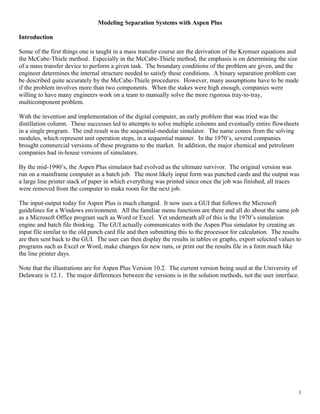
best feed location. An example of the results from a constant performance study is shown below. Stage 15 is
the best choice for the feed.
22
Sensitivity S-1 Summary
VARY 1 COLMN FEED FEEDS STAGE
BTU/HR
10 11 12 13 14 15 16 17 18
3.75e74e74.25e74.5e74.75e7
QREB
23. Estimating the Correct Number of Theoretical Stages
The last thing that needs to be done is to estimate the number theoretical stages. The method is based on the
discussion by Jobson, et.al., on the affect that the vapor load has on the optimum design of equilibrium stages.
The basic proposal is that the total annual cost of constructing and operating the column is a strong function of
the product of the number of stages multiplied by the reflux ratio. The method is to perform a series of case
studies where the total number of stages is varied but the ratio of the feed stage to the total number of stages is
kept constant. The reflux ratio is allowed to vary as discussed above in the section on maintaining constant
column performance. For each run, the number of stages and the reflux ratio is recorded and the product of the
two values is calculated. The number of stages that causes the product to be a minimum is the optimum number
of stages. Usually, about 5 case studies are sufficient to find the optimum number.
23