Downloaded 387 times

![REFERENCES
• [1].Victor Olugbemiga Matthews and Emmanuel Adetiba;Vehicle Accident Alert and
Locator (VAAL); International Journal of Electrical &
• Computer Sciences IJECS-IJENSVol: 11 No: 02
• [2]. Scott J.Weiner; Feasibility of a 802.11VANET Based CarAccident Alert System;
• Northeastern University
• [3]. RoadAccidents In India 2009 – Government of India, Ministry of road transport and
highways, transport research wing, New Delhi
• [4] K. Shiraram, K.V. Kalligudd, “Development and Demonstration of a GPS/GSM Based
Affordable Fleet Management System for Indian Roadways”[Online],
Available:liu.divaportal.org/smash/get/diva2:22123 /FULLTEXT01.pdf
• [5]Megan Bayly, Brian Fildes, Michael Regan, KristieYoung , “Review of crash effectiveness
of IntelligentTransport Systems” Project No. 027763 –TRACE
• [6]B. Huang and J. Preston, “A Literature Review on Motorcycle Collisions”,Transport
Studies Unit Oxford UniversityApril 2004 19](https://image.slidesharecdn.com/finalpresentation-140731035018-phpapp02/75/Design-of-Accident-Detection-and-Alert-System-for-Motor-Cycles-19-2048.jpg)


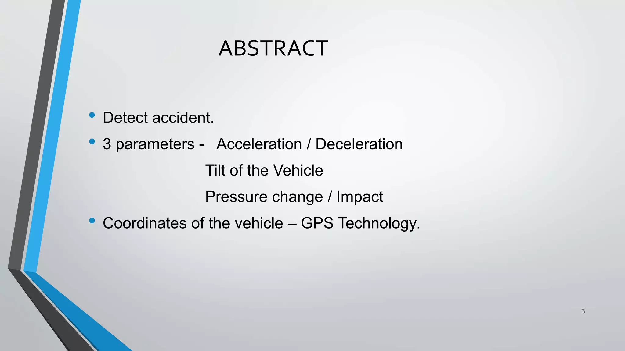
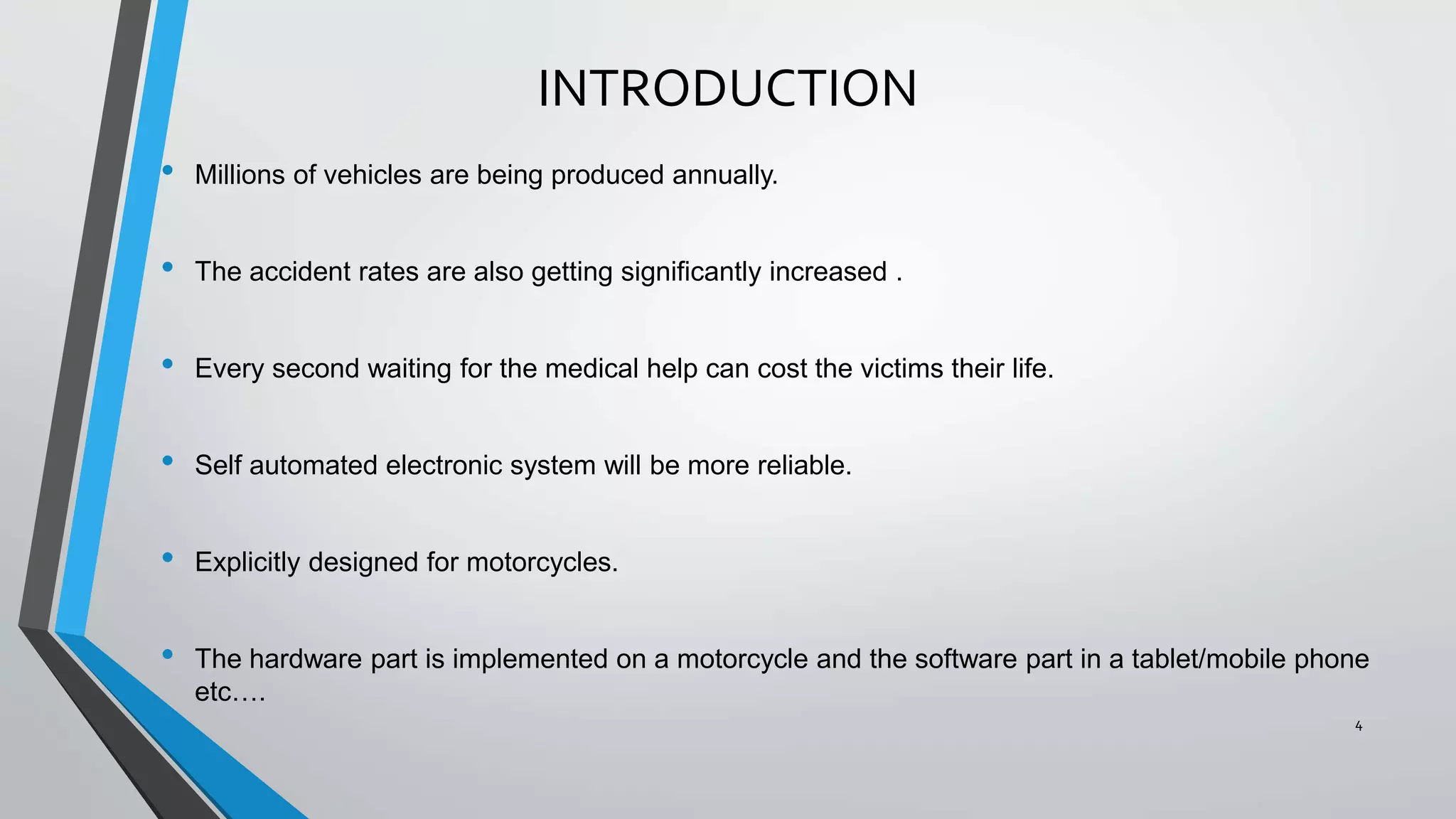
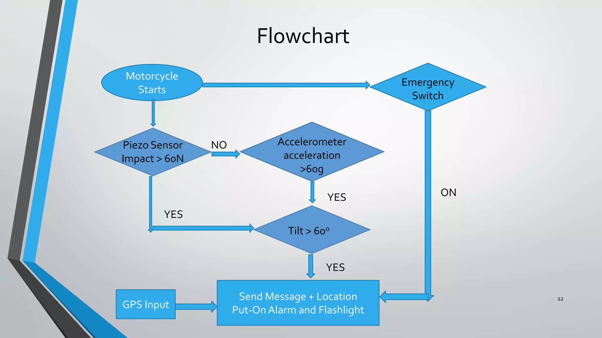
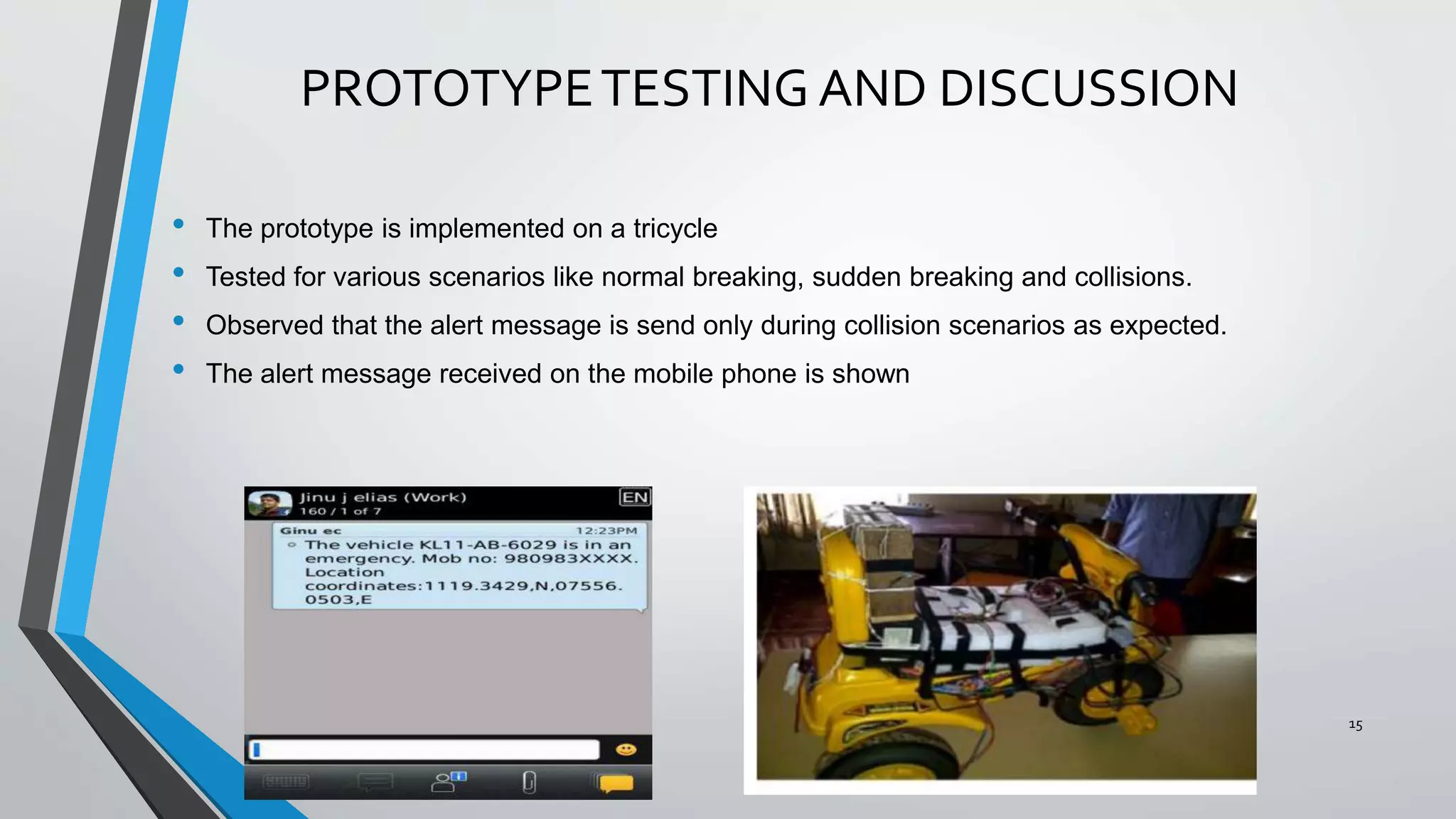
This document describes the design of an accident detection and alert system for motorcycles. The system uses an accelerometer, tilt sensor, and impact sensor to detect if an accident has occurred. It then uses GPS technology to determine the location and sends an alert message with the coordinates to emergency services and contacts. The hardware is installed on the motorcycle and includes sensors connected to a microcontroller. The software analyzes the sensor data to identify if an accident occurred and formats an alert message sent via GSM to designated recipients. The prototype was tested on a tricycle and successfully sent alerts when collisions were detected.


![Smart accident detector and intimator [autosaved]](https://cdn.slidesharecdn.com/ss_thumbnails/smartaccidentdetectorandintimatorautosaved-180331150920-thumbnail.jpg?width=640&height=640&fit=bounds)