1. An isotropic radiator is a hypothetical antenna that radiates power uniformly in all directions. It is used as a reference for comparing the radiation patterns of real antennas.
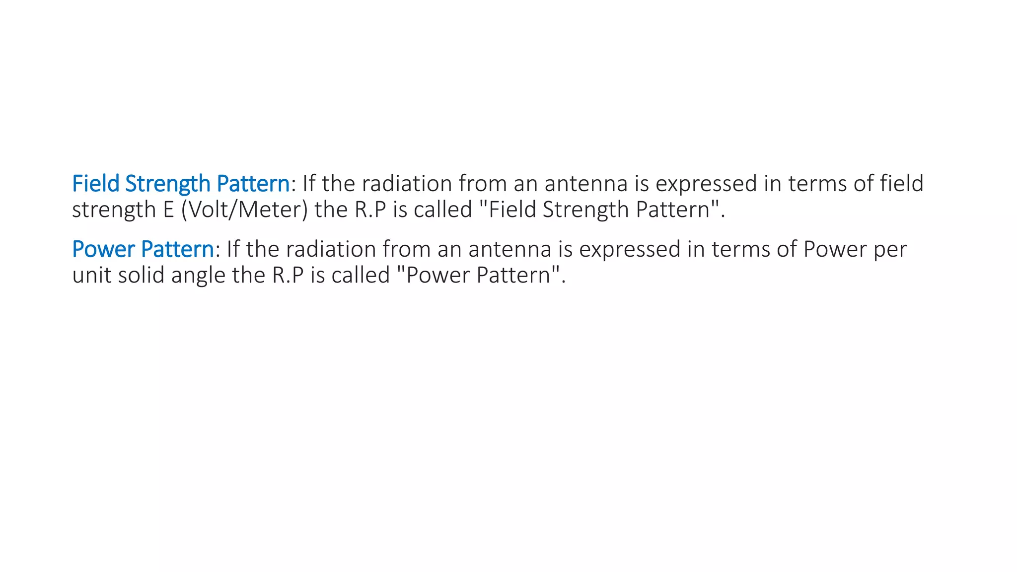
2. A radiation pattern is a graphical representation of an antenna's radiation properties as a function of direction. It shows how strong the antenna's electromagnetic field is in different directions at equal distances from the antenna.
3. The main lobes, side lobes, and back lobes are different parts of an antenna's radiation pattern. The main lobe is in the direction of maximum radiation, while side lobes and back lobes radiate less power.


![3_Antenna Array [Modlue 4] (1).pdf](https://cdn.slidesharecdn.com/ss_thumbnails/3antennaarraymodlue41-220419112111-thumbnail.jpg?width=640&height=640&fit=bounds)


![Antenna lecture course CHapter 2_(2)[1].pdf](https://cdn.slidesharecdn.com/ss_thumbnails/antennach221-240525095938-532f47be-thumbnail.jpg?width=640&height=640&fit=bounds)


