This document provides an overview of key antenna parameters and concepts:
1. It defines an antenna as a device that radiates or receives electromagnetic waves, and describes basic antenna functions and parameters like radiation patterns, beamwidth, and directivity.
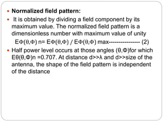
2. It explains key concepts like the normalized radiation pattern, half power beamwidth, and first null beamwidth which characterize an antenna's directivity.
3. It also covers antenna gain, efficiency, effective aperture, and how antennas concentrate radiated power in desired directions compared to an isotropic radiator.


![Normalized power pattern:
Pattern expressed in terms of power per unit area is
called power pattern. Normalizing the power with
respect to maximum value yields normalized power
patterns as a function of angle which is dimensionless
and maximum value is unity.
Pn(θ,Φ)n = S(θ,Φ)/ S(θ,Φ)max---------------- (3)
Where, S(θ,Φ) is the Poynting vector = [ Eθ^2(θ,Φ) +
EΦ^2(θ,Φ) ] / Z0 Wm-2
S(θ,Φ)max is the maximum value of S(θ,Φ), Wm-2
Z0 is the intrinsic impedance of free space = 376.7Ω.
Decibel level is given by dB = 10 log10 Pn(θ,Φ)
Half power levels occurs at those angles (θ,Φ) for
which P(θ,Φ)n =0.5.](https://image.slidesharecdn.com/module3-220808052759-5919fdba/85/MODULE-3-pptx-9-320.jpg)