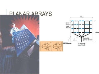
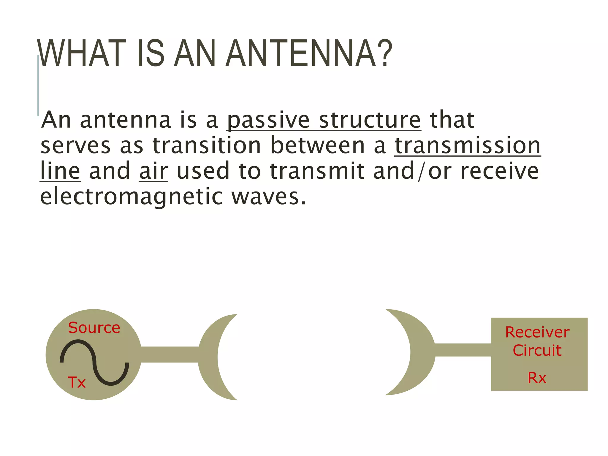
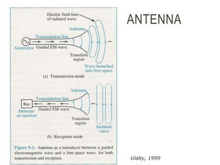
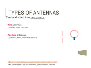
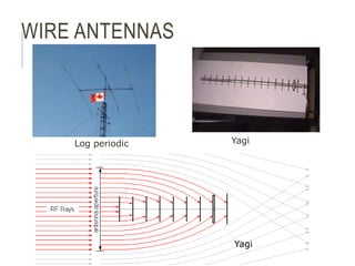
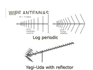
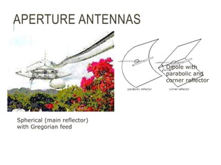
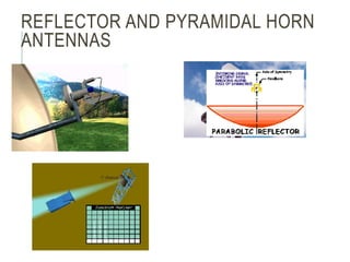
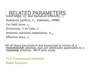
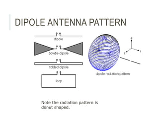
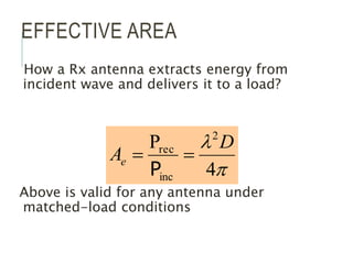
An antenna is a passive structure that serves as a transition between a transmission line and air used to transmit and/or receive electromagnetic waves. Antennas can be divided into two groups: wire antennas such as dipoles, loops, and Yagi-Uda antennas, and aperture antennas such as parabolic, horns, and microstrip antennas. Key antenna parameters include radiation pattern, directivity, gain, beamwidth, impedance, effective area, and polarization.

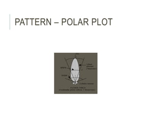
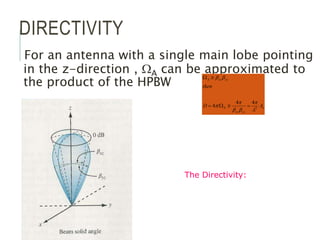
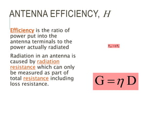
![SOLID ANGLE
s1 = r dq s2 = r sin q dø
s = qr = arc dA = s1 s2
dA = r2 sin q dø dq
= r2 dΩ
q = Plan angle dΩ = Element of solid angle
•The arc of a complete cirlce: • Area of a complete sphere:
= 2pr = 4pr2
•Total angle: = 2p [radianes] •Total solid angle: =4p [rad2]
=4p [sr]
1 steradian (sr) = (1 radian)2](https://image.slidesharecdn.com/antennaanalogies-220801043937-8212efbd/85/Antenna-Analogies-ppt-10-320.jpg)
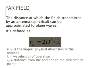
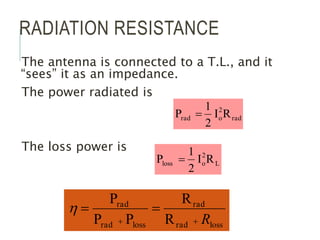
![RADIATION INTENSITY
Is the power density per solid angle:
vector.
Poynting
as
known
also
density
power
the
is
]
[W/m
ˆ
Re 2
r
2
r
H*}
{E
½
where
r
U
r
P
P [W/sr]](https://image.slidesharecdn.com/antennaanalogies-220801043937-8212efbd/85/Antenna-Analogies-ppt-11-320.jpg)
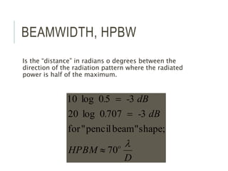
![TOTAL RADIATED POWER BY
ANTENNA
[W]
[W]
W
dS
P
or
d
U
P
r
rad
rad
P
Can be calculated as;](https://image.slidesharecdn.com/antennaanalogies-220801043937-8212efbd/85/Antenna-Analogies-ppt-12-320.jpg)
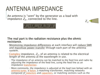
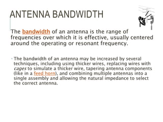
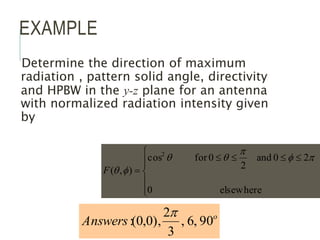
![TOTAL SOLID ANGLE OF AN
ANTENNA
[sr]
)
,
(
4
A W
W d
Fn
p
f
q z
y
x
žA
Patrón
|P |
n
WA
Is as if you changed the
radiation pattern
beam of an antenna
into a pencil beam
shape and find out
what’s the equivalent
solid angle occupied by
this pattern.](https://image.slidesharecdn.com/antennaanalogies-220801043937-8212efbd/85/Antenna-Analogies-ppt-14-320.jpg)
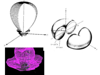
![ISOTROPIC ANTENNA
It’s an hypothetic antenna, i.e., it
does not exist in real life, yet it’s
used as a measuring bar for real
antenna characteristics.
It’s a point source that occupies
a negligible space. Has no
directional preference.
Its pattern is simply a sphere so
it has WA= Wisotropic= 4p
[steradians].
p
f
q
q
p
q
p
f
p
4
sin
)
1
(
)
1
(
0
2
0
4
isotropic
W
W
d
d
d](https://image.slidesharecdn.com/antennaanalogies-220801043937-8212efbd/85/Antenna-Analogies-ppt-15-320.jpg)
![RADAR EQUATION
What is a radar?
Received power by a radar from a single target is
Where s is the backscattering coefficient of the
target [m2]
s
p
2
4
3
2
2
4
e
R
G
P
P o
o
t
r](https://image.slidesharecdn.com/antennaanalogies-220801043937-8212efbd/85/Antenna-Analogies-ppt-31-320.jpg)
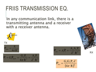
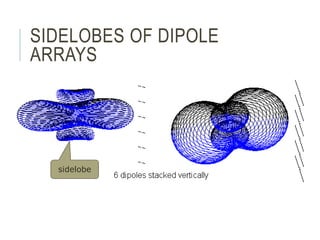
![ANTENNA ARRAYS
Uses many antennas synchronized with each other to increase
Pattern multiplication, AF
[ ]
Factor
Array
Pattern
Antenna
Individual
)
(
r
E
2
sin
2
sin
N
N
AFN
1
-1 1
x
|T (x)|
4
-R
x
0
°
Uniform illumination Tschebyscheff Illumination](https://image.slidesharecdn.com/antennaanalogies-220801043937-8212efbd/85/Antenna-Analogies-ppt-38-320.jpg)