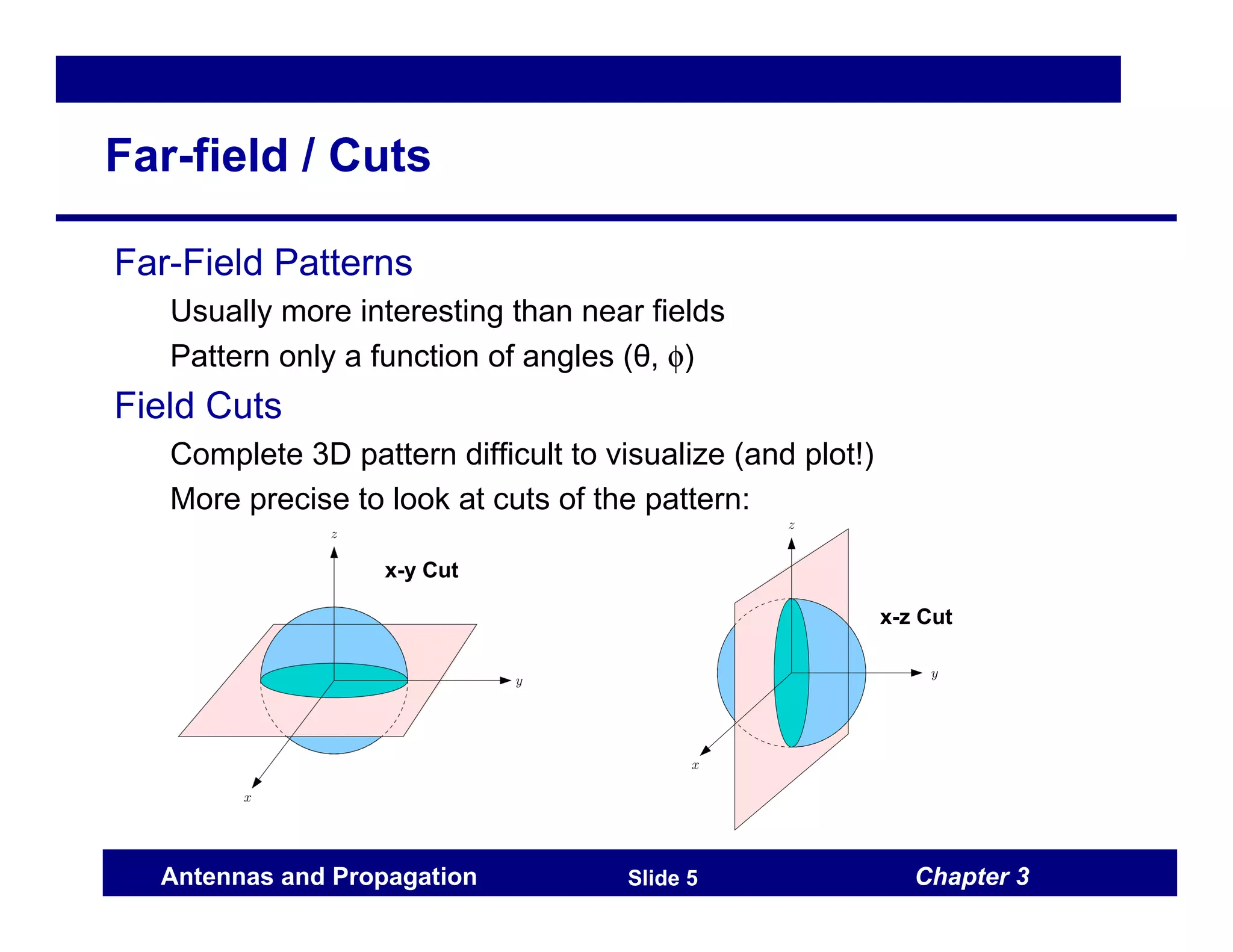
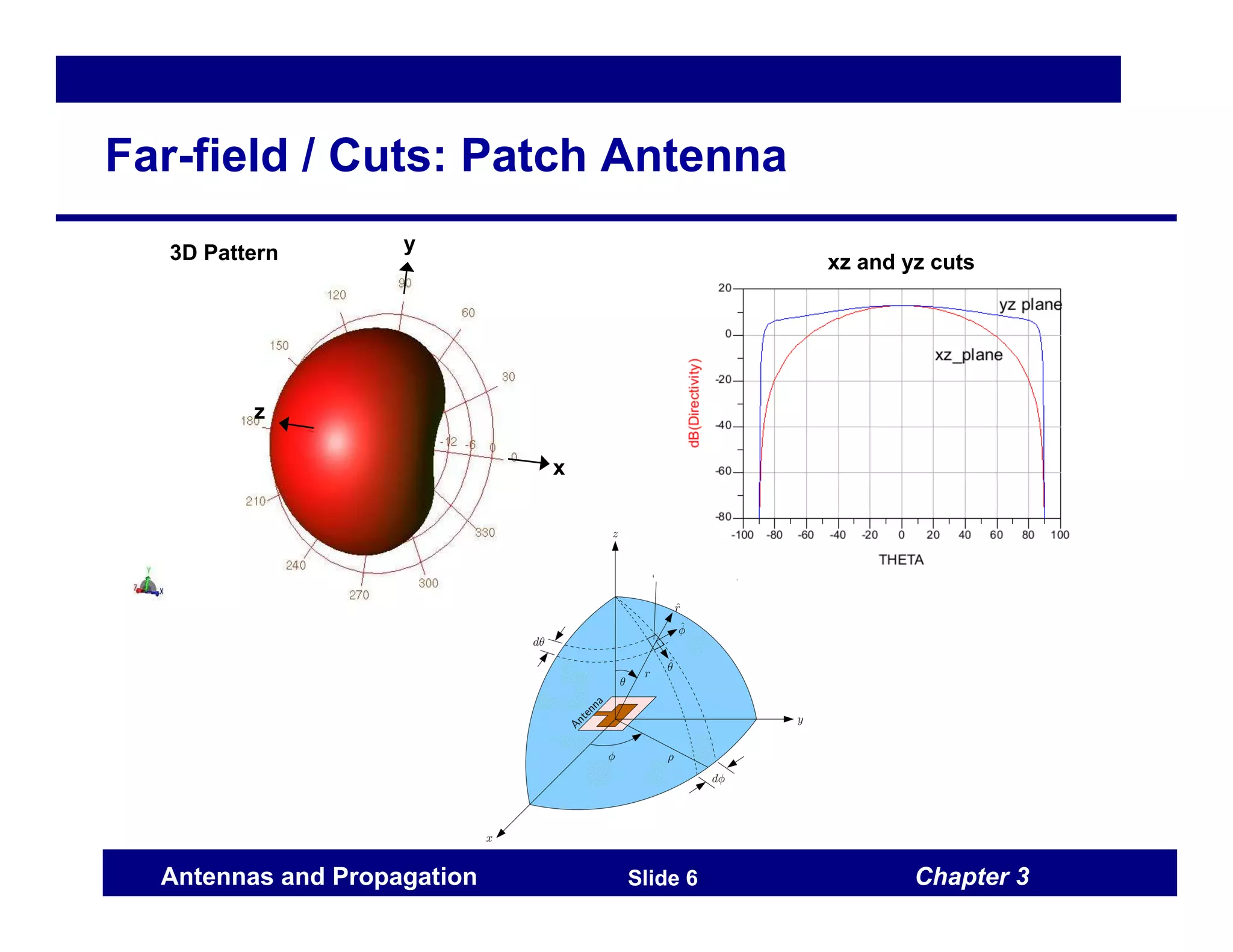
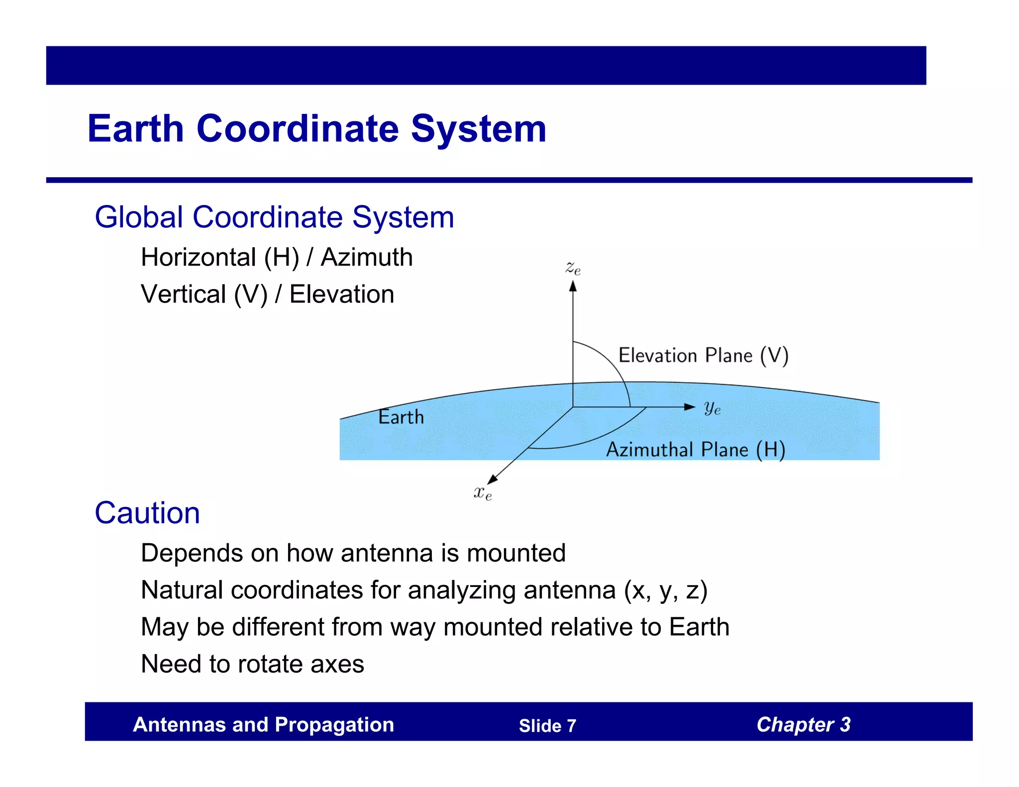
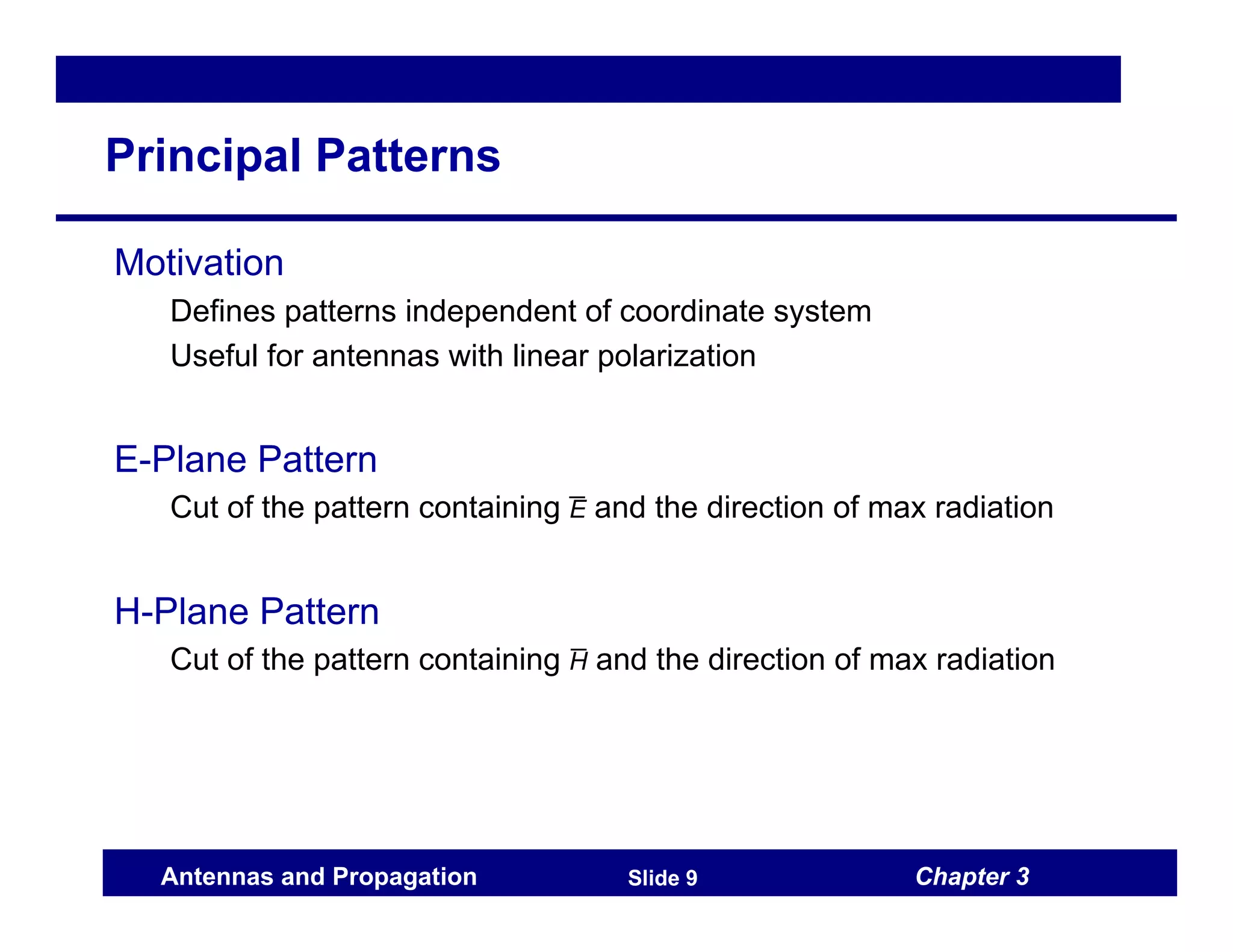
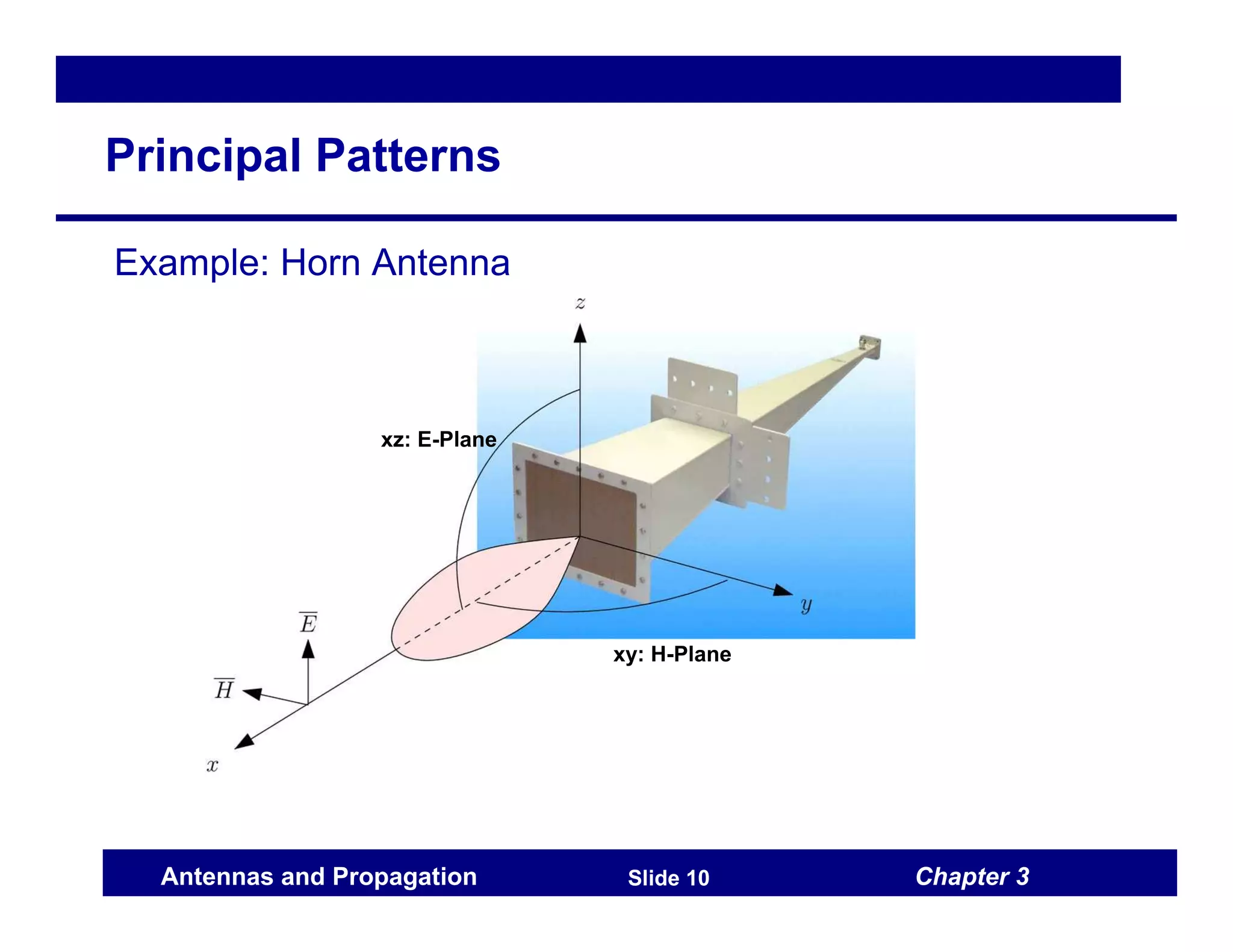
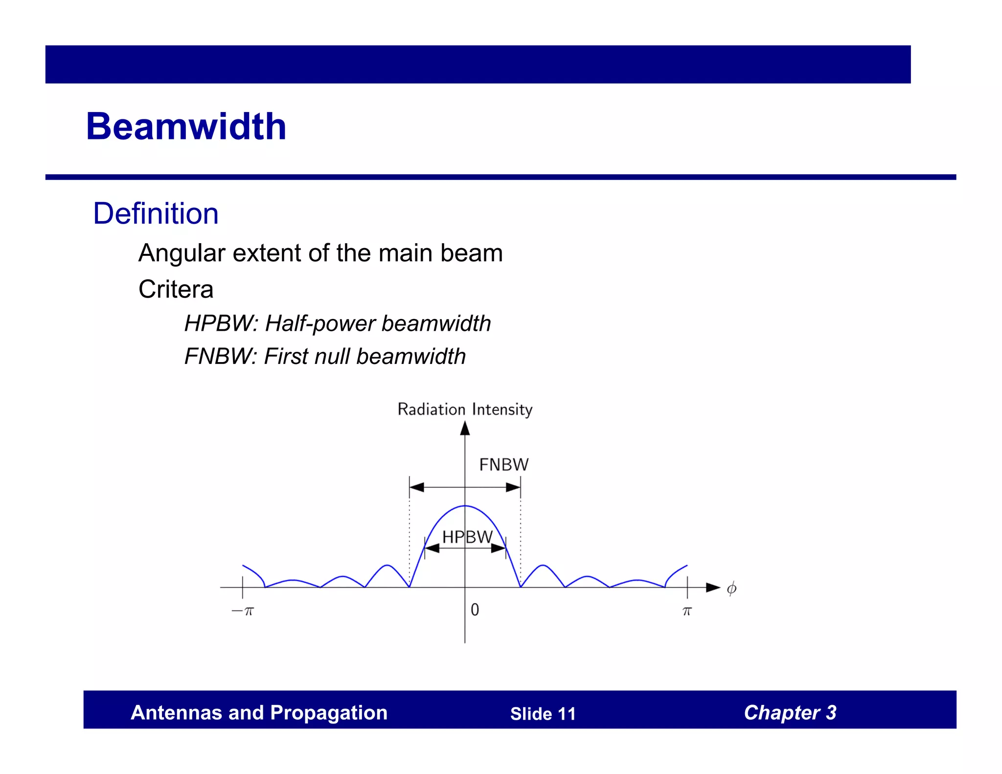
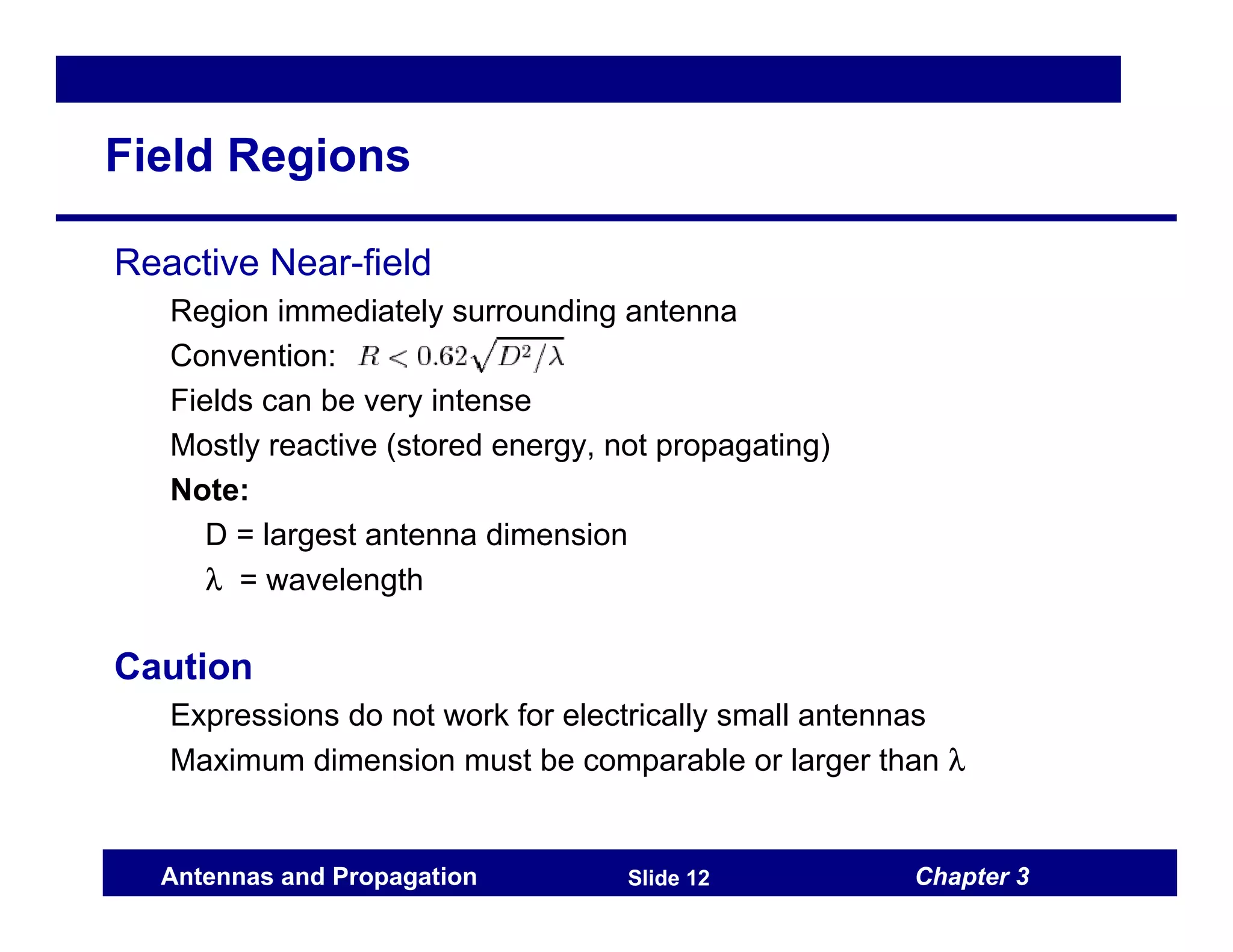
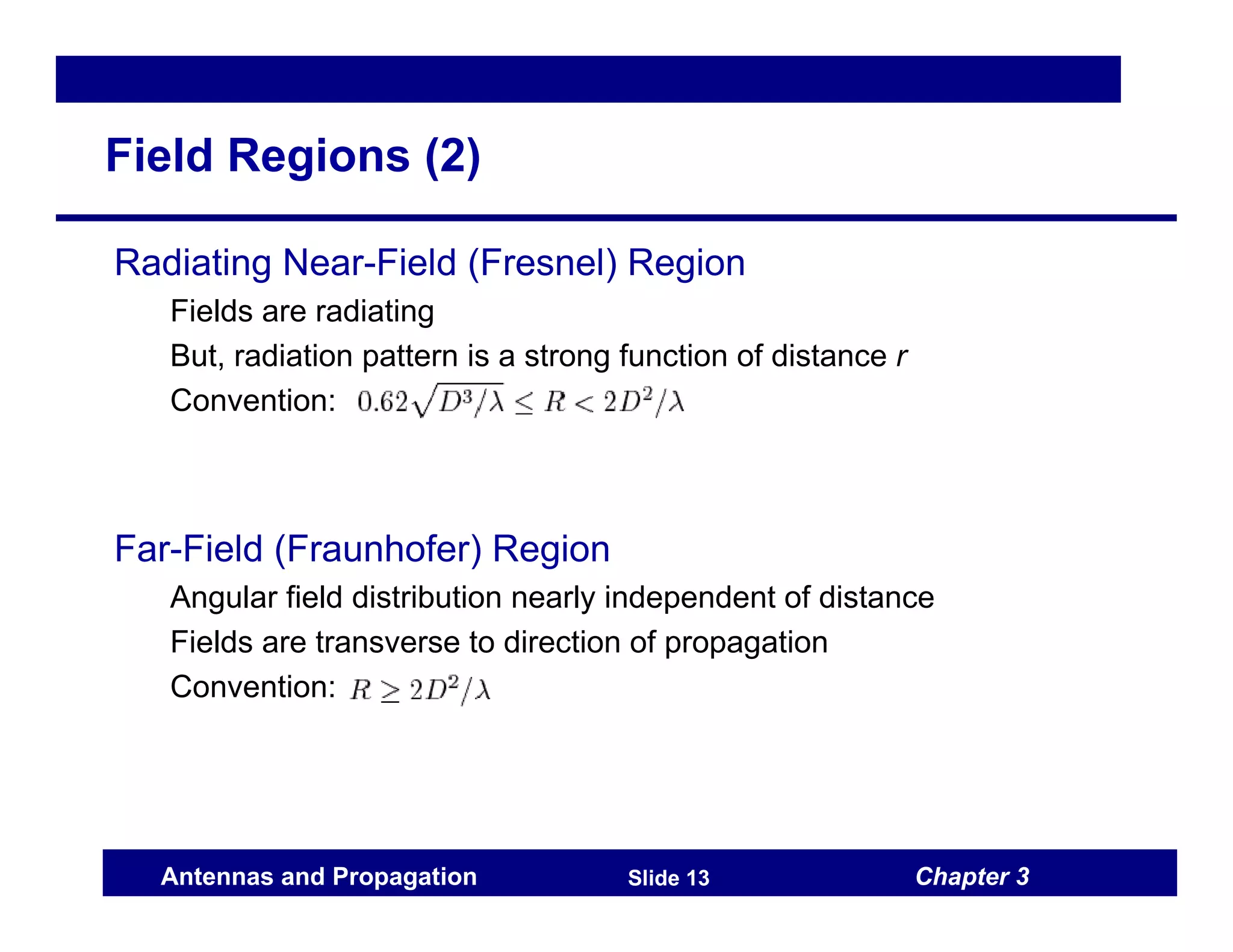
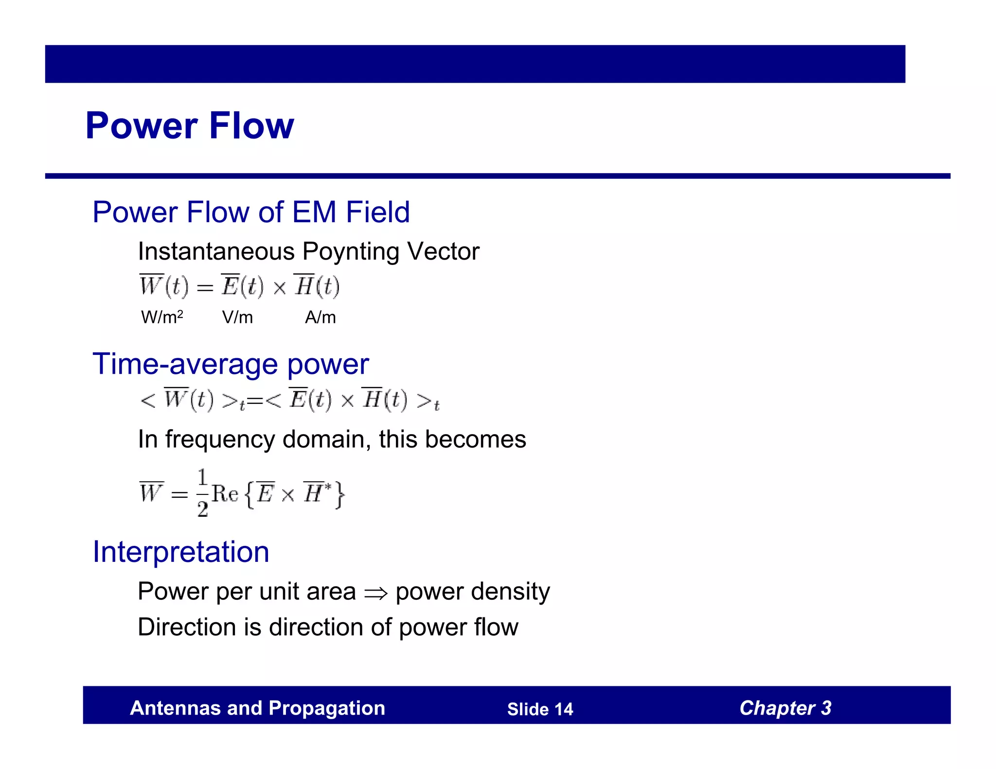
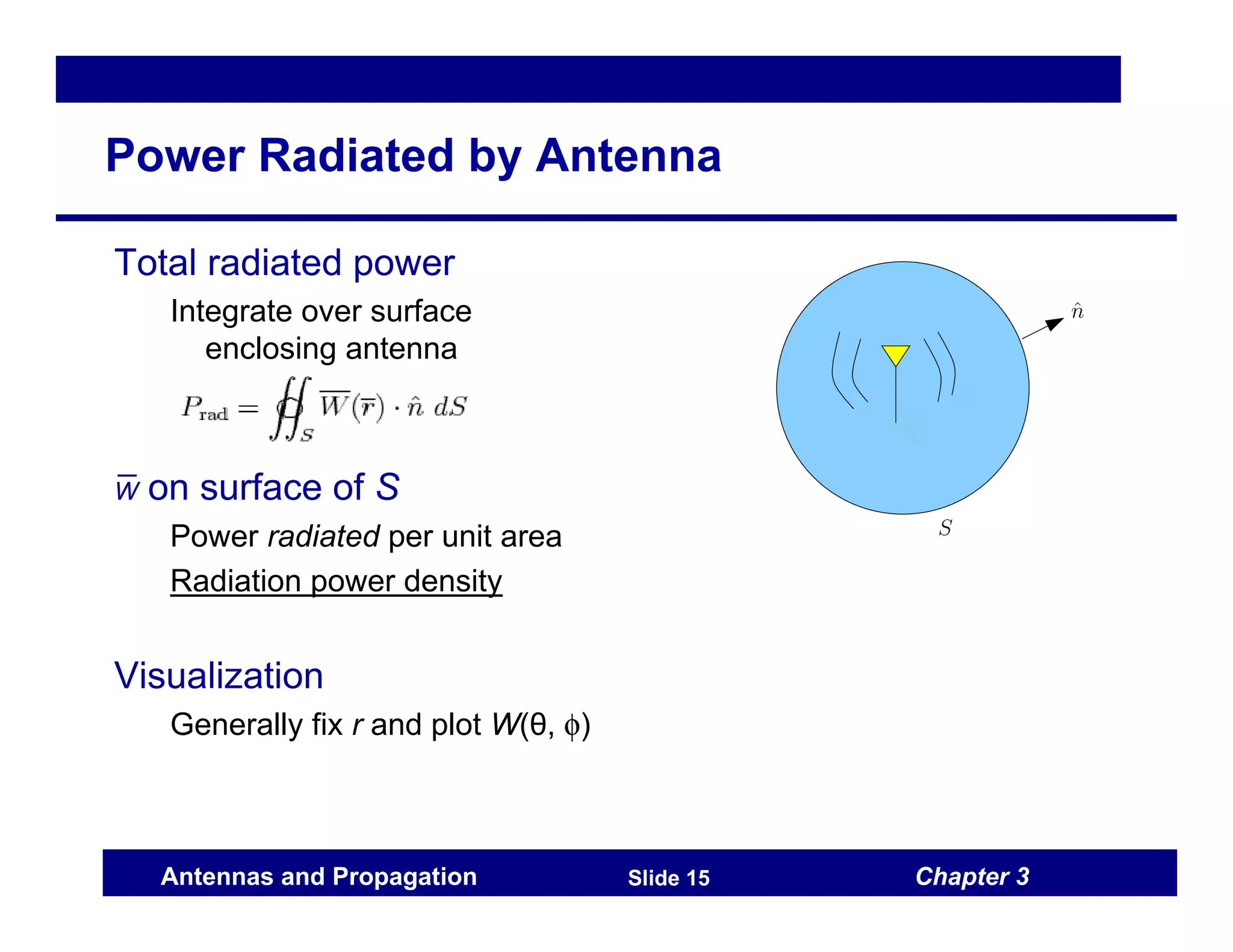
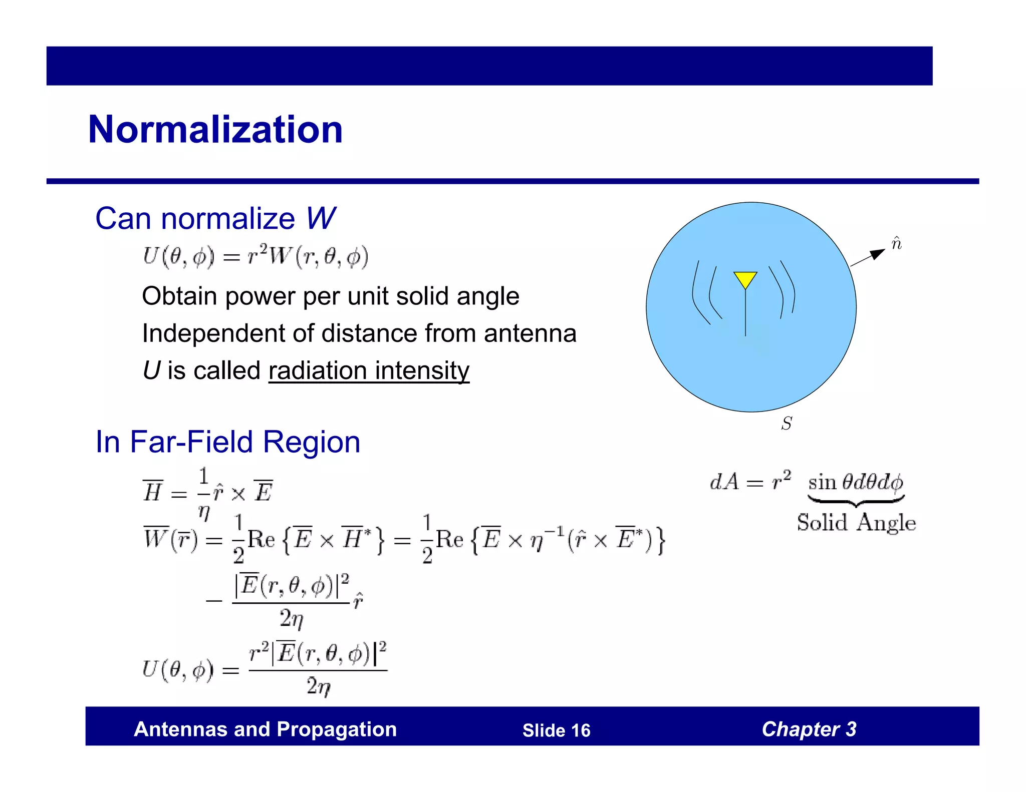
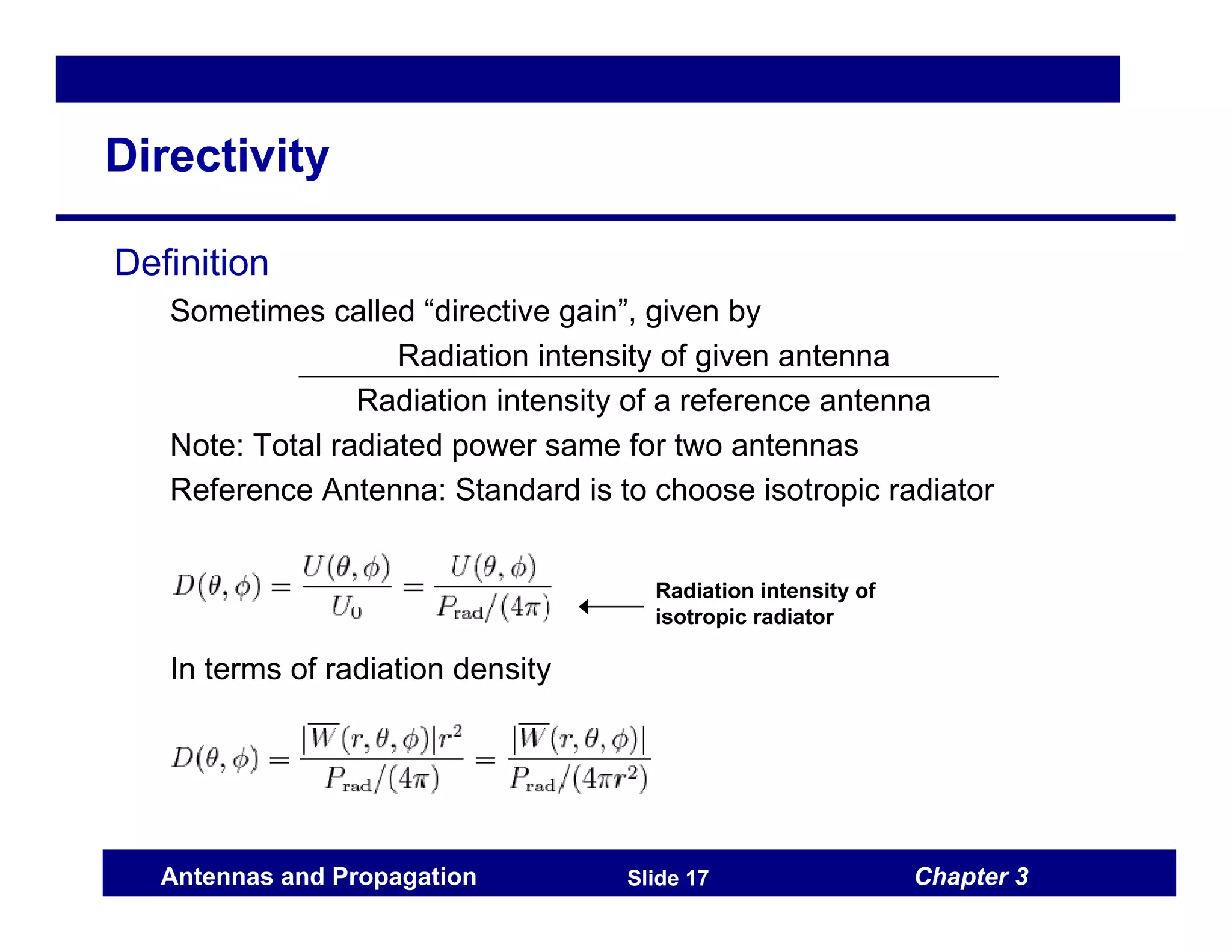
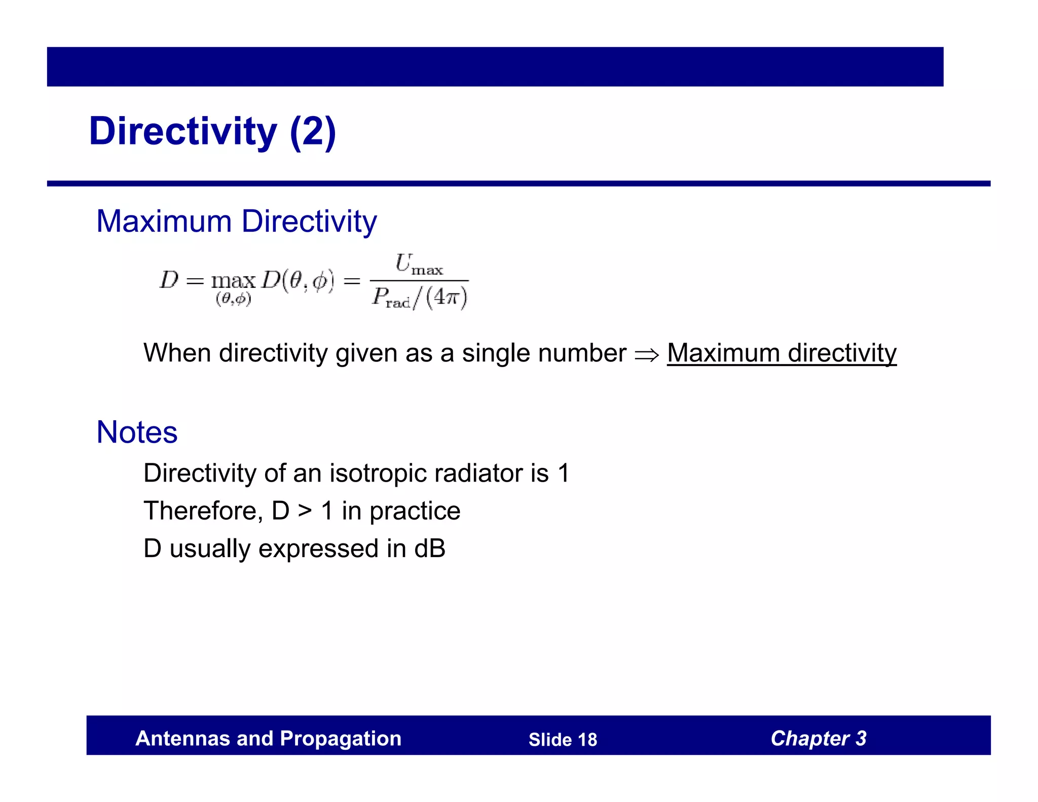
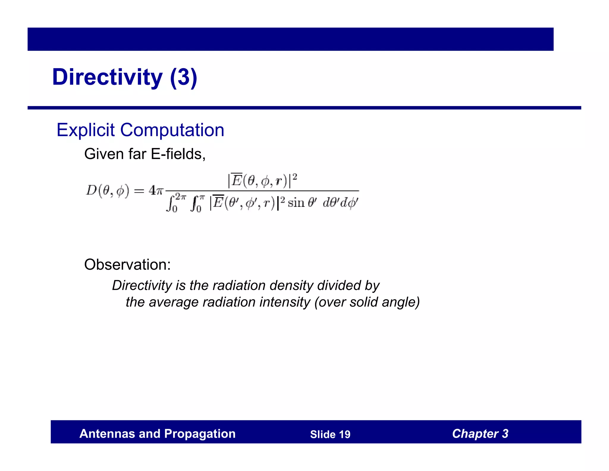
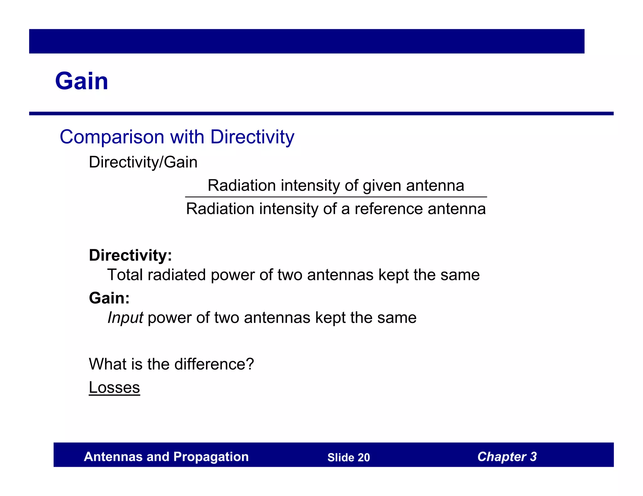
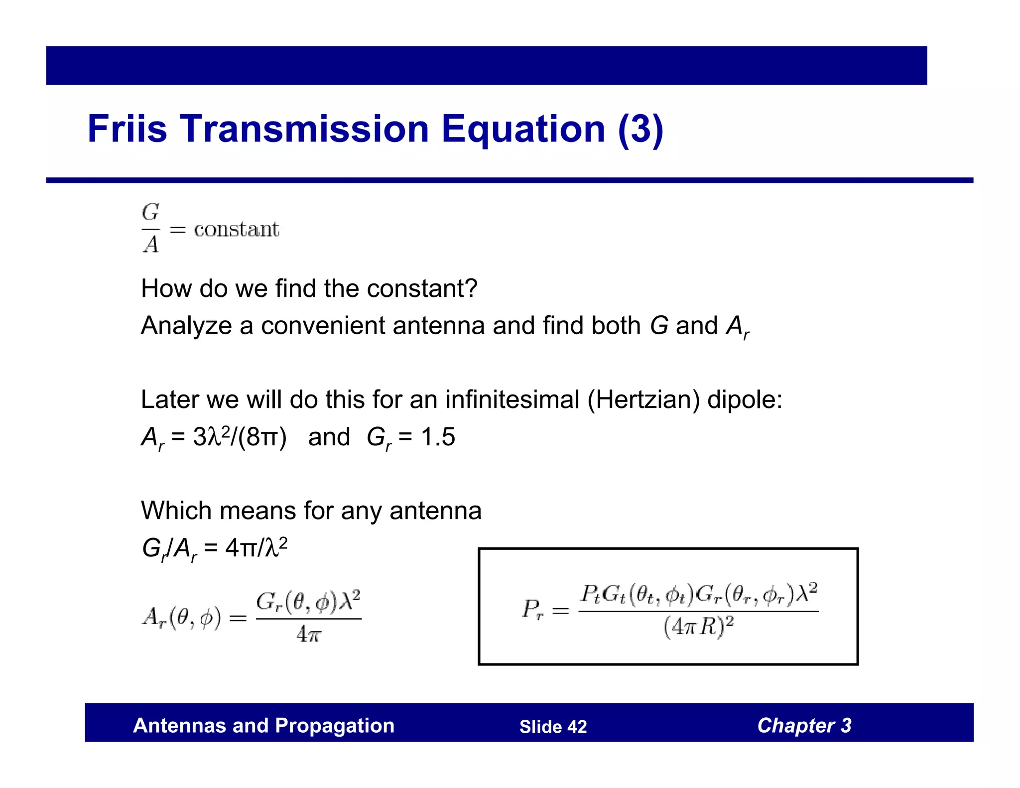
This document introduces standard terms and definitions for antenna parameters. It discusses radiation parameters such as radiation patterns, beamwidth, and far-field regions which describe the spatial selectivity of antennas. It also discusses network parameters including input impedance, return loss, VSWR, and mutual coupling which describe the input/output interface of antennas. Key radiation parameters introduced are directivity, gain, polarization, and power density. Key network parameters introduced are reflection coefficient, Z-parameters, and S-parameters.
This document provides an overview of basic electronics topics including transmission lines, waveguides, and antenna fundamentals. It discusses the characteristics and applications of transmission lines, advantages of using them to reduce electromagnetic interference, and examples of different types of transmission lines. Waveguides are introduced as an alternative to transmission lines at higher frequencies. Key concepts around waveguides such as applications and the expression for cutoff wavelength are summarized. Finally, the document outlines fundamental concepts relating to antennas such as radiation patterns, efficiency, and gain.
An earth station is a type of radio equipment used to communicate with satellites from Earth's surface. It transmits and receives radio waves in extremely high frequency bands to communicate with geosynchronous satellites. Larger antenna apertures are needed for earth stations to achieve higher gains and narrower beam widths for better reception and transmission of signals. The key components of an earth station include a feed, reflector, transmission lines, control system, and power supply. The control system uses an antenna control unit and drive unit to precisely orient the antenna based on signals from a satellite beacon.
This document discusses basic antenna principles for mobile communications. It provides definitions for key antenna concepts like polarization, radiation pattern, half-power beamwidth, gain, impedance, and VSWR. It also describes different types of antennas used in mobile networks including omnidirectional antennas, directional antennas, and antennas designed for particular techniques in GSM and DCS1800 systems like diversity and indoor use. Specific antenna types are also outlined for use in cars, trains, and portable devices.
This document provides a seminar report on the design of microstrip patch antennas. It includes an abstract, table of contents, and sections on antenna parameters, types of antennas including dipoles and Yagi antennas, and software aspects of designing microstrip patch antennas including feed techniques. The report was submitted by a student in partial fulfillment of requirements for a Bachelor of Technology degree.
This document provides an overview of key antenna parameters and concepts:
1. It defines an antenna as a device that radiates or receives electromagnetic waves, and describes basic antenna functions and parameters like radiation patterns, beamwidth, and directivity.
2. It explains key concepts like the normalized radiation pattern, half power beamwidth, and first null beamwidth which characterize an antenna's directivity.
3. It also covers antenna gain, efficiency, effective aperture, and how antennas concentrate radiated power in desired directions compared to an isotropic radiator.
This document provides an overview of basic antenna principles and types used for mobile communications. It discusses the theory behind how antennas work and key definitions such as polarization, radiation pattern, gain and impedance. It also describes different types of antennas used for base stations, vehicles, portable devices and in GSM/DCS networks, including omnidirectional, directional, diversity and indoor antennas. Specific antenna technologies covered include groundplane, skirt, yagi, log-periodic, panel and corner reflector designs.
1. The document discusses various topics related to antenna parameters and radiation patterns. It describes the radiation mechanism of single wire, two wire, and dipole antennas.
2. Current distribution on thin wire antennas is explained. Parameters like radiation patterns, patterns in principal planes, main lobe and side lobes, beam widths, and polarization are discussed.
3. Key points about radiation patterns, coordinate systems, principal plane patterns, and definitions of main lobe, side lobes, half power beamwidth and first null beamwidth are provided.
This document discusses mobile radio propagation and propagation models. It begins by introducing how radio channels are random and time-varying. It then covers the free space propagation model and how received power decreases with distance. Reflection, diffraction, and scattering are described as the main propagation mechanisms. The two-ray ground reflection model is presented to model propagation over large distances. Diffraction is explained using the knife-edge diffraction model. Fresnel zones and diffraction gain are also defined.
This document describes the design and simulation of stacked printed log-periodic antenna arrays for C-band applications. Log-periodic antennas have wide bandwidth and constant impedance over frequency. The paper studies arrays with 5, 7, and 9 radiating elements to increase bandwidth. Simulation results using the method of moments show that bandwidth increases from 17.96% for a 5-element array to 31.53% for a 9-element array. Gain also increases proportionally with the number of elements. The multilayer structure and coupling slot feeding technique contribute to enhanced bandwidth performance.
This document discusses various topics related to antennas and propagation, including:
- The basic functions of antennas for transmission and reception of signals
- Types of radiation and reception patterns that characterize antenna performance
- Common types of antennas like dipole, vertical, and parabolic reflective antennas
- Factors that influence signal propagation over distance like free space loss, noise, multipath interference, and atmospheric effects
- Techniques to improve reliability like diversity combining, adaptive equalization, and forward error correction coding.
This document provides information about different types of antennas. It begins by defining an antenna and describing its functions. It then discusses key antenna concepts like radiation pattern, gain, resistance, bandwidth, beamwidth, polarization, and types of antennas including resonant antennas like half-wave and folded dipoles and non-resonant antennas. Details are given on half-wave dipole antennas including their radiation pattern. Loop antennas are also covered, noting their directivity but low efficiency.
Antennas convert electrical energy to radio waves and vice versa. Microwave frequencies range from 1 GHz to 1000 GHz. Common antenna types include monopole, dipole, parabolic, Yagi, and microstrip. Antenna performance is characterized by properties like radiation pattern, directivity, gain, impedance, efficiency, polarization, bandwidth, and noise temperature. Microstrip patch antennas are low profile, lightweight, inexpensive to manufacture and compatible with microwave integrated circuits. They have a conducting patch on a dielectric substrate mounted over a ground plane.
This document provides an overview of antenna parameters and types. It discusses basic parameters like radiation pattern, beamwidth, gain and directivity. It also covers antenna arrays, measurement techniques, and different antenna types. Key antenna concepts are defined, such as radiation pattern lobes, field regions, radian, steradian, radiation power density, radiation intensity, effective length, aperture and polarization. Common antenna parameters and their calculations are presented. Examples of antenna problems involving these concepts are provided.
The document discusses fundamentals of cellular antennas. It begins by defining an antenna as a device that converts electric power to radio waves and vice versa. An antenna consists of metallic conductors that create oscillating electric and magnetic fields when current is passed through. These fields radiate as electromagnetic waves. The relationship between wavelength, frequency and dipole length is explained - as frequency increases, wavelength and dipole length decrease. Key antenna parameters like gain, VSWR, radiation pattern, polarization, beamwidth and front-to-back ratio are described. Gain measures directivity and is specified in dBi or dBd. VSWR indicates impedance matching between antenna and transmission line. Radiation patterns show power distribution. Different antenna types have specific
The document discusses fundamentals of antenna design and operation. It defines an antenna as a device that provides a transition between guided electromagnetic waves and free space waves. Key points covered include:
- Antennas can transmit and receive electromagnetic waves (reciprocity). Their size and shape determine the frequencies they can handle and radiation patterns.
- Antenna polarization and whether transmitting and receiving antennas match is important for power transfer. Common types include horizontal, vertical, and circular.
- Wavelength is inversely related to frequency, so antenna size varies with operating frequency - lower frequencies use larger antennas.
- Common antenna types like dipoles and monopoles are discussed along with their radiation patterns, gains, and effects of
This document provides information on fundamental antenna parameters and concepts. It discusses:
1. How antennas convert guided waves into radiating waves and vice versa.
2. Key antenna parameters including radiation pattern, directivity, radiation resistance, efficiency, gain, bandwidth, reciprocity, effective aperture, beamwidth, and polarization matching.
3. The Friis transmission formula for calculating received power between two antennas in free space based on their gains, wavelength, and distance.
This document discusses antennas and propagation in wireless communication systems. It covers topics such as antenna characteristics, radiation patterns, polarization, Maxwell's equations, far-field approximation, Hertzian dipole antenna model, radiated power flux density, normalized radiation intensity, antenna gain, directivity, radiation resistance, and different antenna types including dipole and Yagi antennas. Examples are provided to analyze antenna properties such as radiated power, resistance, directionality, and beamwidth for dipole antennas of different lengths.
Design of rectangular patch antenna array using advanced design methodologyIISRT
This document describes the design of rectangular patch antenna arrays. It discusses designing a single patch element, including selecting substrate properties and calculating patch dimensions. It then covers array design, including arranging elements with proper spacing and designing feed networks. Specifically, it presents the design of 1x2 and 2x2 rectangular patch antenna arrays. The key parameters discussed are return loss, VSWR, and impedance matching using techniques like quarter-wave transformers. Simulation results showing return loss and Smith charts are presented to validate the designed arrays operate as intended around 2.4GHz.
Design of rectangular patch antenna array using advanced design methodologyRamesh Patriotic
This document describes the design of rectangular patch antenna arrays. It discusses designing a single rectangular patch element, including selecting substrate properties and calculating patch dimensions. It then covers array design, including arranging elements with proper spacing and designing feed networks. Specifically, it presents the design of 1x2, 2x2, and 1x4 rectangular patch antenna arrays. Simulation results show the return loss and Smith charts for each array, indicating good impedance matching at the target frequency of 2.4GHz. Radiation patterns are also presented, demonstrating the increase in gain and directivity provided by antenna arrays.
Iisrt 3-design of rectangular patch antenna array using advanced design metho...IISRTJournals
This document describes the design of rectangular patch antenna arrays. It discusses designing a single patch element and determining its physical parameters. It then covers designing 1x2 and 2x2 array configurations using rectangular patches. The feed networks are designed using quarter-wave transformers to match impedances. Simulation results show the return loss and Smith charts with deep S11 values at the operating frequency of 2.4GHz, indicating good impedance matching.
This document provides an overview of important considerations for selecting an antenna for short range wireless applications. It discusses various antenna types (PCB, chip, whip, wire), parameters to consider (radiation pattern, gain, bandwidth, size, cost), antenna theory basics, and measurement techniques. The document also describes antenna reference designs from Texas Instruments for different frequency bands and provides additional antenna resources. Selecting the proper antenna is key to optimizing system performance and reducing costs.
1. The document discusses various types of antennas used for different applications, including aperture antennas, leaky-wave antennas, and the largest radio telescopes.
2. It describes key antenna concepts such as radiation patterns, polarization, gain, beamwidth, and effective aperture. Radiation patterns show the distribution of power radiated or received by the antenna.
3. Antenna polarization and gain are important characteristics that determine how effectively the antenna can transmit or receive radio waves in different directions.
1. Radio propagation involves mechanisms like reflection, diffraction, scattering that affect the strength of the radio signal over distance.
2. Reflection occurs when the radio wave impinges on objects larger than the wavelength like buildings, walls. Diffraction allows signals to propagate beyond obstacles. Scattering occurs from objects smaller than the wavelength.
3. Propagation models like free space and two-ray ground reflection are used to predict signal strength over large distances. Factors like Fresnel zones and knife-edge diffraction also impact signal propagation around obstacles.
1. The document discusses radiation from a two-wire transmission line connected to an antenna. It explains how electric and magnetic fields are created between the conductors when a voltage is applied. Electromagnetic waves travel along the transmission line and enter the antenna.
2. When part of the antenna structure is removed, free space waves are formed by connecting the open ends of the electric field lines. The constant phase point of these waves moves outward at the speed of light.
3. Key terms related to antennas like radial power flow, radiation resistance, uniform current distribution, principle planes, beam width, polarization, effective aperture area, directive gain, power gain, and dual characteristics are defined in the document.
This document provides an overview of antenna properties and types. It discusses key antenna properties like gain, aperture, directivity, bandwidth, polarization, and effective length. It then describes several common antenna types including dipole antennas, monopole antennas, loop antennas, log-periodic antennas, travelling wave antennas like helical and Yagi-Uda, and reflector antennas like corner reflectors and parabolic reflectors. Radiation patterns are also characterized in terms of main beam, sidelobes, half power beamwidth, and sidelobe level.
The document provides information about Vallurupalli Nageswara Rao Vignana Jyothi Institute of Engineering and Technology. It includes the vision, mission and quality policy of the institute which focus on producing global citizens through quality education and meeting technological challenges. The document also contains the lesson plan for the subject "Computer Organization" taught to third year students. The lesson plan details the prerequisites, objectives, outcomes, syllabus, teaching methodologies and assessment criteria for the course.
The document discusses various parameters that characterize antennas including frequency, radiation pattern, directivity, gain, beamwidths, sidelobes, impedance, radiation intensity, and polarization. It provides definitions and explanations of these key antenna parameters and includes diagrams to illustrate concepts such as radiation patterns, field regions, beamwidths, and units of antenna gain. The document aims to give an overview and introduction to fundamental antenna parameters needed to understand and design basic antenna types and their performance.
The document discusses the main principles of radiation from antennas. It begins by explaining that antennas are usually made of metal and function by creating differences in potential that control charge distribution and generate electromagnetic fields. Radiation occurs when charges encounter discontinuities like bends that change their speed. Resonant structures like dipole antennas produce continuous radiation through oscillating charges. The document then examines the electric and magnetic fields produced by elementary sources like Hertzian dipoles and how these far fields propagate in free space according to Maxwell's equations.
This document provides an overview of antennas and wave propagation. It begins by defining key antenna parameters such as radiation pattern, polarization, directivity and others. It then discusses various antenna types including dipole antennas, folded dipole antennas, Yagi-Uda antennas and horn antennas. Design considerations for different types of reflector antennas such as plane reflectors, corner reflectors and parabolic reflectors are also covered. The document aims to introduce students to the fundamental concepts and terminology used in antennas and wave propagation.
The document discusses small loop antennas, also known as magnetic dipole antennas. It provides details on:
1) The vector magnetic potential, current density, and electric and magnetic fields generated by a small loop antenna. The fields are similar to those of a Hertzian dipole.
2) Key parameters of small loop antennas including power density, directivity, total radiated power, and radiation resistance. Increasing the diameter or using a ferrite core can increase the antenna's efficiency.
3) Practical examples of small loop antennas including a precision VLF antenna coil and an AM/LW loopstick antenna for tuning between 100 kHz to 1710 kHz when used with a variable capacitor.
The document discusses the physical layer of the network protocol stack. It describes how information can be encoded into either analog or digital signals and transmitted over various physical media types, including guided media like twisted pair cables and unguided media like radio waves. It explains concepts like bandwidth, frequency spectrum, and how different physical layer technologies like radio, microwave, and satellite communication work.
The document discusses small loop antennas, also known as magnetic dipole antennas. It provides details on:
1) The vector magnetic potential, current density, and electric and magnetic fields generated by a small loop antenna. The fields are similar to those of a Hertzian dipole.
2) Key parameters of small loop antennas including power density, directivity, total radiated power, and radiation resistance. Increasing the diameter or using a ferrite core can increase the antenna's efficiency.
3) Practical examples of small loop antennas including a precision VLF antenna coil and an AM/LW loopstick antenna for tuning between 100 kHz to 1710 kHz when used with a variable capacitor.
This document discusses various topics related to antennas and propagation. It describes what antennas are, their characteristics, and different types of antennas like dipole, parabolic, and arrays. It also covers radiation patterns, antenna gain, and different propagation modes like ground wave, sky wave, and line-of-sight. Key factors affecting line-of-sight transmission are discussed, including attenuation, free space loss, noise from thermal, intermodulation, crosstalk and impulse sources, and atmospheric absorption and multipath effects. Common antenna types and their uses as well as concepts like radiation patterns, antenna gain, and propagation modes are summarized.
This document discusses key concepts related to wireless communication antennas. It defines important antenna parameters such as gain, directivity, effective aperture, radiation resistance, bandwidth, beamwidth, and input impedance. It also describes common antenna types including dipole antennas, folded dipoles, Yagi arrays, and parabolic reflector antennas. Finally, it discusses the history of antenna development and the roles antennas play in spatial filtering, polarization filtering, impedance transformation, and propagating electromagnetic waves.
This document discusses radio wave propagation through the ionosphere. It begins by outlining the syllabus which includes factors affecting propagation such as the ground wave, ionosphere effects, refraction, reflection, skip distance and fading. It then discusses these factors in more detail over 3 pages, explaining ground wave propagation, the structure of the ionosphere consisting of E, F1, F2 and D layers, and how radio waves are refracted and reflected by the ionosphere to allow communication beyond line of sight.
An antenna is a device that transmits or receives electromagnetic waves. It acts as a transition between guided and free space electromagnetic wave propagation. Common types of antennas include wire antennas like dipoles and loops, aperture antennas like parabolic dishes and horns, and antenna arrays. Key antenna parameters that are described include radiation patterns, beam area and efficiency, directivity, gain, and radiation resistance. Common topics like polarization, reflection and refraction, guided wave propagation, launching electromagnetic waves, and reciprocity are also covered at a high level.
This document provides an overview of basic antenna theory concepts. It begins with an outline that reviews basic antenna types like monopoles, slots, patches and reflector antennas. It then discusses topics like radiation patterns, gain, polarization, equivalent circuits and efficiency. The document provides examples of different antenna types and applications. It explains key antenna concepts such as radiation patterns, power patterns versus field patterns, and principal patterns. Overall, the document serves as an introduction to refresh fundamental concepts in antenna physics.
1. The document discusses key characteristics of antenna radiation patterns including the radiation pattern, which shows the antenna's electric and magnetic fields in 3D space. Common pattern types include omnidirectional, broadside, and endfire.
2. Important parameters that quantify antenna patterns are defined, such as directivity which compares an antenna's power concentration to an isotropic radiator, half-power beamwidth, and maximum sidelobe level.
3. Radiation intensity, which is independent of distance from the antenna, is introduced. It allows defining the total radiated power by integrating over solid angle rather than area.
This document provides an introduction to different types of antennas, including their parameters and applications. It discusses wire antennas like dipoles and monopoles, patch antennas, reflector antennas, arrays, and more. Examples and images are given for different antenna types. Key concepts covered include radiation patterns, input impedance, link budgets, and choosing antennas based on an application's requirements. References for further reading on antennas are also provided.
This chapter discusses electromagnetic waves and Maxwell's equations. Maxwell's equations describe how changing electric fields produce magnetic fields and vice versa. This allows electromagnetic waves to propagate through space as oscillating electric and magnetic fields that are perpendicular to each other and the direction of propagation. The speed of propagation is calculated to be the speed of light. Electromagnetic waves carry energy and momentum and include radio waves, microwaves, infrared, visible light, ultraviolet, X-rays and gamma rays.
This document is the first chapter of a textbook on wireless communication networks and systems. It provides an overview of the history and development of wireless technology, from early inventions like the wireless telegraph to modern cellular networks and trends toward 5G networks and the Internet of Things. It also discusses some of the technical challenges of wireless communication like multipath fading and the need for modulation techniques and error control coding to overcome issues caused by the wireless channel.
This document discusses mobile radio propagation and includes the following key points:
- It describes different types of radio waves and frequency bands used in mobile communications. Propagation mechanisms like reflection, diffraction and scattering are also covered.
- Path loss models for free space, urban, suburban and open areas are presented. Higher path loss is observed in urban versus open areas.
- Slow fading relates to long-term signal strength variations while fast fading involves short-term fluctuations. Slow fading is modeled by log-normal distribution and fast fading by Rayleigh or Rician distributions depending on presence of line of sight.
- Characteristics of fast fading such as level crossing rate and fading rate are defined.
The document discusses different types of small antennas that can be used for EnOcean-based products, including quarter-wave monopole antennas, helical antennas, chip antennas, and PCB antennas. It emphasizes that the antenna design is critical for RF performance and range. A quarter-wave monopole antenna provides good overall performance but may be too long at lower frequencies. A helical antenna can significantly reduce the size while maintaining good performance. PCB antennas can be a low-cost solution if enough ground plane is available. The size and shape of the ground plane is important for all these antenna types to function properly.
This document contains questions for a question bank covering five units on integrated circuits and applications:
Unit I covers the classification of integrated circuits and operational amplifiers, including ideal and practical op-amp characteristics, the op-amp 741 pin diagram and features, and op-amp modes of operation.
Unit II discusses various op-amp applications including adders, subtractors, voltage followers, instrumentation amplifiers, and integrators and differentiators. It also covers comparators, Schmitt triggers, and multivibrators.
Unit III is about active filters and oscillators, including first order filters, waveform generators, and phase locked loops.
Unit IV describes timer ICs and applications using IC 555
This document contains an assignment for a Linear IC Applications class. It includes 6 questions about active filters, waveform generators, the IC 555 timer, multivibrators, phase locked loops, and digital to analog and analog to digital converters. The questions cover topics like first and second order low pass, high pass, band pass and band reject filters. It also addresses RC phase shift oscillators, Wien bridge oscillators, and the functional block diagram and applications of the IC 555 timer in monostable and astable multivibrators. The document defines lock in range, capture range and pull in time as they relate to phase locked loops, and includes drawing the block diagram of a PLL and PLL IC 565. It concludes
More from RAVIKUMAR Digital Signal Processing (20)
TIME DIVISION MULTIPLEXING TECHNIQUE FOR COMMUNICATION SYSTEMHODECEDSIET
Time Division Multiplexing (TDM) is a method of transmitting multiple signals over a single communication channel by dividing the signal into many segments, each having a very short duration of time. These time slots are then allocated to different data streams, allowing multiple signals to share the same transmission medium efficiently. TDM is widely used in telecommunications and data communication systems.
### How TDM Works
1. **Time Slots Allocation**: The core principle of TDM is to assign distinct time slots to each signal. During each time slot, the respective signal is transmitted, and then the process repeats cyclically. For example, if there are four signals to be transmitted, the TDM cycle will divide time into four slots, each assigned to one signal.
2. **Synchronization**: Synchronization is crucial in TDM systems to ensure that the signals are correctly aligned with their respective time slots. Both the transmitter and receiver must be synchronized to avoid any overlap or loss of data. This synchronization is typically maintained by a clock signal that ensures time slots are accurately aligned.
3. **Frame Structure**: TDM data is organized into frames, where each frame consists of a set of time slots. Each frame is repeated at regular intervals, ensuring continuous transmission of data streams. The frame structure helps in managing the data streams and maintaining the synchronization between the transmitter and receiver.
4. **Multiplexer and Demultiplexer**: At the transmitting end, a multiplexer combines multiple input signals into a single composite signal by assigning each signal to a specific time slot. At the receiving end, a demultiplexer separates the composite signal back into individual signals based on their respective time slots.
### Types of TDM
1. **Synchronous TDM**: In synchronous TDM, time slots are pre-assigned to each signal, regardless of whether the signal has data to transmit or not. This can lead to inefficiencies if some time slots remain empty due to the absence of data.
2. **Asynchronous TDM (or Statistical TDM)**: Asynchronous TDM addresses the inefficiencies of synchronous TDM by allocating time slots dynamically based on the presence of data. Time slots are assigned only when there is data to transmit, which optimizes the use of the communication channel.
### Applications of TDM
- **Telecommunications**: TDM is extensively used in telecommunication systems, such as in T1 and E1 lines, where multiple telephone calls are transmitted over a single line by assigning each call to a specific time slot.
- **Digital Audio and Video Broadcasting**: TDM is used in broadcasting systems to transmit multiple audio or video streams over a single channel, ensuring efficient use of bandwidth.
- **Computer Networks**: TDM is used in network protocols and systems to manage the transmission of data from multiple sources over a single network medium.
### Advantages of TDM
- **Efficient Use of Bandwidth**: TDM all
Literature Review Basics and Understanding Reference Management.pptxDr Ramhari Poudyal
Three-day training on academic research focuses on analytical tools at United Technical College, supported by the University Grant Commission, Nepal. 24-26 May 2024
Advanced control scheme of doubly fed induction generator for wind turbine us...IJECEIAES
This paper describes a speed control device for generating electrical energy on an electricity network based on the doubly fed induction generator (DFIG) used for wind power conversion systems. At first, a double-fed induction generator model was constructed. A control law is formulated to govern the flow of energy between the stator of a DFIG and the energy network using three types of controllers: proportional integral (PI), sliding mode controller (SMC) and second order sliding mode controller (SOSMC). Their different results in terms of power reference tracking, reaction to unexpected speed fluctuations, sensitivity to perturbations, and resilience against machine parameter alterations are compared. MATLAB/Simulink was used to conduct the simulations for the preceding study. Multiple simulations have shown very satisfying results, and the investigations demonstrate the efficacy and power-enhancing capabilities of the suggested control system.
Electric vehicle and photovoltaic advanced roles in enhancing the financial p...IJECEIAES
Climate change's impact on the planet forced the United Nations and governments to promote green energies and electric transportation. The deployments of photovoltaic (PV) and electric vehicle (EV) systems gained stronger momentum due to their numerous advantages over fossil fuel types. The advantages go beyond sustainability to reach financial support and stability. The work in this paper introduces the hybrid system between PV and EV to support industrial and commercial plants. This paper covers the theoretical framework of the proposed hybrid system including the required equation to complete the cost analysis when PV and EV are present. In addition, the proposed design diagram which sets the priorities and requirements of the system is presented. The proposed approach allows setup to advance their power stability, especially during power outages. The presented information supports researchers and plant owners to complete the necessary analysis while promoting the deployment of clean energy. The result of a case study that represents a dairy milk farmer supports the theoretical works and highlights its advanced benefits to existing plants. The short return on investment of the proposed approach supports the paper's novelty approach for the sustainable electrical system. In addition, the proposed system allows for an isolated power setup without the need for a transmission line which enhances the safety of the electrical network
CHINA’S GEO-ECONOMIC OUTREACH IN CENTRAL ASIAN COUNTRIES AND FUTURE PROSPECTjpsjournal1
The rivalry between prominent international actors for dominance over Central Asia's hydrocarbon
reserves and the ancient silk trade route, along with China's diplomatic endeavours in the area, has been
referred to as the "New Great Game." This research centres on the power struggle, considering
geopolitical, geostrategic, and geoeconomic variables. Topics including trade, political hegemony, oil
politics, and conventional and nontraditional security are all explored and explained by the researcher.
Using Mackinder's Heartland, Spykman Rimland, and Hegemonic Stability theories, examines China's role
in Central Asia. This study adheres to the empirical epistemological method and has taken care of
objectivity. This study analyze primary and secondary research documents critically to elaborate role of
china’s geo economic outreach in central Asian countries and its future prospect. China is thriving in trade,
pipeline politics, and winning states, according to this study, thanks to important instruments like the
Shanghai Cooperation Organisation and the Belt and Road Economic Initiative. According to this study,
China is seeing significant success in commerce, pipeline politics, and gaining influence on other
governments. This success may be attributed to the effective utilisation of key tools such as the Shanghai
Cooperation Organisation and the Belt and Road Economic Initiative.
ACEP Magazine edition 4th launched on 05.06.2024Rahul
This document provides information about the third edition of the magazine "Sthapatya" published by the Association of Civil Engineers (Practicing) Aurangabad. It includes messages from current and past presidents of ACEP, memories and photos from past ACEP events, information on life time achievement awards given by ACEP, and a technical article on concrete maintenance, repairs and strengthening. The document highlights activities of ACEP and provides a technical educational article for members.
A SYSTEMATIC RISK ASSESSMENT APPROACH FOR SECURING THE SMART IRRIGATION SYSTEMSIJNSA Journal
The smart irrigation system represents an innovative approach to optimize water usage in agricultural and landscaping practices. The integration of cutting-edge technologies, including sensors, actuators, and data analysis, empowers this system to provide accurate monitoring and control of irrigation processes by leveraging real-time environmental conditions. The main objective of a smart irrigation system is to optimize water efficiency, minimize expenses, and foster the adoption of sustainable water management methods. This paper conducts a systematic risk assessment by exploring the key components/assets and their functionalities in the smart irrigation system. The crucial role of sensors in gathering data on soil moisture, weather patterns, and plant well-being is emphasized in this system. These sensors enable intelligent decision-making in irrigation scheduling and water distribution, leading to enhanced water efficiency and sustainable water management practices. Actuators enable automated control of irrigation devices, ensuring precise and targeted water delivery to plants. Additionally, the paper addresses the potential threat and vulnerabilities associated with smart irrigation systems. It discusses limitations of the system, such as power constraints and computational capabilities, and calculates the potential security risks. The paper suggests possible risk treatment methods for effective secure system operation. In conclusion, the paper emphasizes the significant benefits of implementing smart irrigation systems, including improved water conservation, increased crop yield, and reduced environmental impact. Additionally, based on the security analysis conducted, the paper recommends the implementation of countermeasures and security approaches to address vulnerabilities and ensure the integrity and reliability of the system. By incorporating these measures, smart irrigation technology can revolutionize water management practices in agriculture, promoting sustainability, resource efficiency, and safeguarding against potential security threats.
2. Chapter 3
Antennas and Propagation Slide 2
Introduction
Purpose
Introduce standard terms and definitions for antennas
Need a common language to specify performance
Two types of parameters
1. Radiation parameters
What is the spatial selectivity of the element?
Indicate where is power sent / collected from.
2. Network parameters
What does the antenna present at its port(s)?
Indicates requirements for system it connects to.
3. Chapter 3
Antennas and Propagation Slide 3
Outline: Radiation Parameters
Goal
Precisely define the spatial selectivity of antennas
Main Concepts
Radiation patterns, pattern cuts, beamwidth
Field regions: far-field, near-field
Power density of EM fields
Radiation Power Density
Directivity / Gain
4. Chapter 3
Antennas and Propagation Slide 4
Radiation Patterns
Definition
Graphical representation of radiation (or reception) properties
Function of spatial coordinates
Possible quantities
Power density (most common)
Field strength
Directivity
Gain
Phase
Polarization
5. Chapter 3
Antennas and Propagation Slide 5
Far-field / Cuts
Far-Field Patterns
Usually more interesting than near fields
Pattern only a function of angles (θ, φ)
Field Cuts
Complete 3D pattern difficult to visualize (and plot!)
More precise to look at cuts of the pattern:
x-y Cut
x-z Cut
6. Chapter 3
Antennas and Propagation Slide 6
Far-field / Cuts: Patch Antenna
xz and yz cuts
3D Pattern
x
y
z
7. Chapter 3
Antennas and Propagation Slide 7
Earth Coordinate System
Global Coordinate System
Horizontal (H) / Azimuth
Vertical (V) / Elevation
Caution
Depends on how antenna is mounted
Natural coordinates for analyzing antenna (x, y, z)
May be different from way mounted relative to Earth
Need to rotate axes
8. Chapter 3
Antennas and Propagation Slide 8
General Pattern Types
Isotropic Pattern
Power (or field) equally radiated in all directions
In practice, does not exist!
Used as a reference
Omnidirectional Pattern
Radiated field constant in azimuth (φ)
May vary with elevation (θ)
Examples: dipole or small loop
Directional Pattern
Radiates significantly more power in some directions than others
“Directional in the ___________ plane”
Significantly more directional than a half-wave dipole
9. Chapter 3
Antennas and Propagation Slide 9
Principal Patterns
Motivation
Defines patterns independent of coordinate system
Useful for antennas with linear polarization
E-Plane Pattern
Cut of the pattern containing E̅ and the direction of max radiation
H-Plane Pattern
Cut of the pattern containing H̅ and the direction of max radiation
10. Chapter 3
Antennas and Propagation Slide 10
Principal Patterns
Example: Horn Antenna
xz: E-Plane
xy: H-Plane
11. Chapter 3
Antennas and Propagation Slide 11
Beamwidth
Definition
Angular extent of the main beam
Critera
HPBW: Half-power beamwidth
FNBW: First null beamwidth
12. Chapter 3
Antennas and Propagation Slide 12
Field Regions
Reactive Near-field
Region immediately surrounding antenna
Convention:
Fields can be very intense
Mostly reactive (stored energy, not propagating)
Note:
D = largest antenna dimension
λ = wavelength
Caution
Expressions do not work for electrically small antennas
Maximum dimension must be comparable or larger than λ
13. Chapter 3
Antennas and Propagation Slide 13
Field Regions (2)
Radiating Near-Field (Fresnel) Region
Fields are radiating
But, radiation pattern is a strong function of distance r
Convention:
Far-Field (Fraunhofer) Region
Angular field distribution nearly independent of distance
Fields are transverse to direction of propagation
Convention:
14. Chapter 3
Antennas and Propagation Slide 14
Power Flow
Power Flow of EM Field
Instantaneous Poynting Vector
Time-average power
In frequency domain, this becomes
Interpretation
Power per unit area ⇒ power density
Direction is direction of power flow
W/m2 V/m A/m
15. Chapter 3
Antennas and Propagation Slide 15
Power Radiated by Antenna
Total radiated power
Integrate over surface
enclosing antenna
W̅ on surface of S
Power radiated per unit area
Radiation power density
Visualization
Generally fix r and plot W(θ, φ)
16. Chapter 3
Antennas and Propagation Slide 16
Normalization
Can normalize W
Obtain power per unit solid angle
Independent of distance from antenna
U is called radiation intensity
In Far-Field Region
17. Chapter 3
Antennas and Propagation Slide 17
Directivity
Definition
Sometimes called “directive gain”, given by
Radiation intensity of given antenna
Radiation intensity of a reference antenna
Note: Total radiated power same for two antennas
Reference Antenna: Standard is to choose isotropic radiator
In terms of radiation density
Radiation intensity of
isotropic radiator
18. Chapter 3
Antennas and Propagation Slide 18
Directivity (2)
Maximum Directivity
When directivity given as a single number ⇒ Maximum directivity
Notes
Directivity of an isotropic radiator is 1
Therefore, D > 1 in practice
D usually expressed in dB
19. Chapter 3
Antennas and Propagation Slide 19
Directivity (3)
Explicit Computation
Given far E-fields,
Observation:
Directivity is the radiation density divided by
the average radiation intensity (over solid angle)
20. Chapter 3
Antennas and Propagation Slide 20
Gain
Comparison with Directivity
Directivity/Gain
Radiation intensity of given antenna
Radiation intensity of a reference antenna
Directivity:
Total radiated power of two antennas kept the same
Gain:
Input power of two antennas kept the same
What is the difference?
Losses
21. Chapter 3
Antennas and Propagation Slide 21
Gain (2)
Computation
Efficiency
et is the total efficiency of the antenna
et = er ec ed
where
er = Reflection efficiency 1-|Γ|2
ec = Conduction efficiency
ed = Dielectric efficiency
Radiation Efficiency
et = Prad / Pin = Rrad / (Rrad + RL)
22. Chapter 3
Antennas and Propagation Slide 22
Antenna Polarization
Definition
TX: Polarization of the radiated wave produced by the antenna
RX: Polarization of incident plane wave yielding maximum available
output power at the antenna terminals
Directional Dependence
Polarization can be defined
1. As a function of direction
2. For direction of maximum gain
(assumed if no direction specified)
23. Chapter 3
Antennas and Propagation Slide 23
Review of EM Polarization
Definition
For a plane wave propagating in the - direction
Instantaneous field is
where
Polarization = Shape of curve traced by tip of E vector in xy plane
Maximum Amplitude
of x,y Components
Phase
of x,y Components
24. Chapter 3
Antennas and Propagation Slide 24
Review of EM Polarization (2)
In xy plane
Traces out an ellipse in general
Special Cases
Linear polarization
Circular Polarization
25. Chapter 3
Antennas and Propagation Slide 25
Outline: Network Parameters
Goal
Precisely define the “input/output interface” of the antenna
Main Concepts
Input impedance
Reflection coefficient / VSWR
Mutual Coupling, Z-parameters, S-parameters
26. Chapter 3
Antennas and Propagation Slide 26
Antenna Input Characteristics
Input Impedance
Have seen that mismatch reduces efficiency of antenna system
To ensure maximum transmission,
Conjugate match condition:
In Practice
Antennas designed to have convenient input impedance (50 Ohms)
Matching network integrated in antenna
Transforms raw antenna impedance to Z0
27. Chapter 3
Antennas and Propagation Slide 27
Antenna Input Characteristics (2)
Nominal input impedance is Z0
Actual impedance varies slightly with frequency
Also, no fabrication process is perfect
Variations in impedance from one antenna to next
Characterizing input Impedance
Graphical representations
Impedance
(Ohms)
Re/Im Parts of Impedance
Smith Chart
28. Chapter 3
Antennas and Propagation Slide 28
Antenna Input Characteristics (3)
Problem with Providing Input Impedance
Impedance varies from one device to the next
(fabrication variations)
Every antenna must be measured
More common approach
Antenna design assumes system impedance of Z0
Specify:
1. Worst case reflection, or
2. Voltage standing wave ratio (VSWR)
29. Chapter 3
Antennas and Propagation Slide 29
Reflection Coefficient
Definition
Γ = V-/V+ on the feeding line
|Γ|2 indicates what fraction of power is reflected
Power lost, because not delivered to antenna
Return Loss
Related to Γ:
Return Loss = – 20 log10 |Γ|
IEEE definition: Return Loss as a positive value (hence – sign)
Worst case return loss
Return Loss min = – 20 log10 |Γ|max
30. Chapter 3
Antennas and Propagation Slide 30
VSWR
Definition
Voltage standing wave ratio
(max voltage to min voltage on feed line)
Reason:
Wave ratio was easy to measure with old slotted waveguides
Still used in many specifications of RF parts / antennas
Expressed as a ratio
i.e. 1.2:1 or 2:1
If a single number, indicates worst-case value
31. Chapter 3
Antennas and Propagation Slide 31
Mutual Coupling
Where important
Antenna arrays
Multimode or multipolarization antennas ⇒ Multiple ports
Basic problem
Antenna elements close together
Signals on one element ⇒ create signal on other element
Usually want to receive signals on antennas independently
SP Algorithms
Typically are degraded by the effect
34. Chapter 3
Antennas and Propagation Slide 34
Characterizations: S-Parameters
Network Characterizations
2. S-Parameters (S = “scattering”)
More useful for high-freq. analysis
You should see relation to Γ
Worst-case coupling: 20 log10 |S21|max
Often quoted as minimum isolation: -20 log10 |S21|max
1 2
36. Chapter 3
Antennas and Propagation Slide 36
Antenna Bandwidth
Definition
Range of frequencies over which the antenna conforms
to some specified standard
“Specified standard” includes any performance metrics so far:
Patterns
Gain
Efficiency
Side lobe levels
Beamwidth
Input Impedance
Isolation
Etc.
37. Chapter 3
Antennas and Propagation Slide 37
Antenna Bandwidth (2)
Wideband antennas
Bandwidth expressed as a ratio
fmax/fmin : 1
E.g. 10:1 ⇒ Maximum frequency ten times greater than minimum
frequency
Narrowband Antennas
Usually express as “fractional bandwidth,” or
(fmax – fc)/fc x 100 where fc ≈ (fmax + fmin)/2.
E.g. 5% fractional bandwidth ⇒
5% deviation from center frequency can be tolerated
38. Chapter 3
Antennas and Propagation Slide 38
Summarizing
So far ...
Have characterized a single antenna (patterns, port characteristics)
But,
How do TX/RX antennas work together?
How do we use parameters to estimate gain of whole link?
Simplest Case: Free Space Propagation
Governed by Friis Transmission Equation
More complicated cases
Multipath, shadowing
Consider later in course (Propagation part of class!)
39. Chapter 3
Antennas and Propagation Slide 39
Friis Transmission Equation
Radiation power density from transmitter
40. Chapter 3
Antennas and Propagation Slide 40
Friis Transmission Equation (2)
Next, power collected by receive antenna
Need to derive notion of receiving aperture or “effective area”
Assuming antenna captures power from area Ar
Turns out that Ar is a directional quantity related to Gr
41. Chapter 3
Antennas and Propagation Slide 41
Relation of Effective Area and Gain
Consider again (assumed)
Now consider making 1=RX and 2=TX (switch roles)
Know by reciprocity that received power same
Comparing, this means that
Since we have specified nothing about antennas,
(switched TX/RX)
(ANY reciprocal antenna!)
42. Chapter 3
Antennas and Propagation Slide 42
Friis Transmission Equation (3)
How do we find the constant?
Analyze a convenient antenna and find both G and Ar
Later we will do this for an infinitesimal (Hertzian) dipole:
Ar = 3λ2/(8π) and Gr = 1.5
Which means for any antenna
Gr/Ar = 4π/λ2
43. Chapter 3
Antennas and Propagation Slide 43
Summary
Standard terms and definitions for antennas
Radiation Parameters
Network (port) Parameters
Friis Transmission Equation
Next time: Start analyzing specific antenna types