This document provides steps for creating a finite element model and analysis of a truss structure in ANSYS. It describes:
1) Defining element types, material properties, and applying boundary conditions like constraints and loads.
2) Creating the mesh by directly defining nodes and elements, without using solid model geometry.
3) Solving the model and comparing numerical results to theoretical calculations to verify the model is working correctly.
![Step 1: Geometry
Thisanalysisdirectlygeneratesthe nodesandelementsforthe finiteelementmodel,therefore
there isno needtocreate solidmodel geometry.
Step 2: Define ElementTypes
2-1. Define the elementtype requiredforthis model
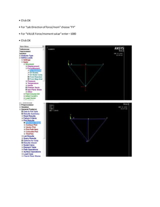
• Preprocessor>ElementType>Add/Edit/Delete
• Clickthe “Add...”buttontobringup the Library of ElementTypes
• Inthe leftcolumnunder“Structural Mass”choose “Link”
• Inthe rightcolumn,choose “3D finitstn180”
• ClickOK
• Close the ElementTypes dialogbox
2-2. Assignsectionpropertiesto the linkelements
• Preprocessor>Sections>Link>Add
• For the LinkSectionID,enter1
• ClickOK
• For [SECDATA] SectionDataLinkarea,enter1
• ClickOK
Step 3: Define Material Properties
3-1. Define the material properties
• Preprocessor>MaterialProps>Material Models](https://image.slidesharecdn.com/kidproject-200127155849/85/mechanical-apdl-and-ansys-steps-1-320.jpg)
![Step 1: Geometry
Thisanalysisdirectlygeneratesthe nodesandelementsforthe finiteelementmodel,therefore
there isno needtocreate solidmodel geometry.
Step 2: Define ElementTypes
2-1. Define the elementtype requiredforthis model
• Preprocessor>ElementType>Add/Edit/Delete
• Clickthe “Add...”buttontobringup the Library of ElementTypes
• Inthe leftcolumnunder“Structural Mass”choose “Link”
• Inthe rightcolumn,choose “3D finitstn180”
• ClickOK
• Close the ElementTypes dialogbox
2-2. Assignsectionpropertiesto the linkelements
• Preprocessor>Sections>Link>Add
• For the LinkSectionID,enter1
• ClickOK
• For [SECDATA] SectionDataLinkarea,enter1
• ClickOK
Step 3: Define Material Properties
3-1. Define the material properties
• Preprocessor>MaterialProps>Material Models](https://image.slidesharecdn.com/kidproject-200127155849/75/mechanical-apdl-and-ansys-steps-1-2048.jpg)
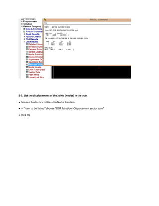
![• Change “Elem/Attrib numbering” to “Element numbers”
• ClickOK
4-3. Plot the finite element mesh
• Utility Menu>Plot>Elements
4-4. Change to the isometric view
• Clickthe “Isometric View” button in the Pan Zoom Rotate menu
4-5. Turn element shape display on
• Utility Menu>PlotCtrls>Style>Size and Shape...
• Turn “[/ESHAPE]Display of element shapes based on real constant descriptions” on
• ClickOK
4-6. Return to the frontview
• Clickthe “Front View” button in the Pan Zoom Rotate menu
4-7. Turn element shape display off
• Utility Menu>PlotCtrls>Style>Size and Shape...
• Turn “[/ESHAPE]Display of element shapes based on real constant descriptions” off
• ClickOK
4-8. Turn element numbering off
• Utility Menu>PlotCtrls>Numbering...
• Change “Elem/Attrib numbering” to “No numbering”
• ClickOk
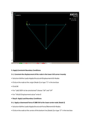
Step 5: Apply Constraint Boundary Conditions
5-1. Constrain the fixed end of the beam
• Solution>Define Loads>Apply>Structural>Displacement>On Keypoints
• Clickon the keypoint at the origin or specify Keypoint 1 in the text box
• ClickOK
• For “Lab2 DOFsto be constrained” choose “All DOF”](https://image.slidesharecdn.com/kidproject-200127155849/85/mechanical-apdl-and-ansys-steps-12-320.jpg)