Download as PDF, PPTX

![Improper Symmetry Constraint Use
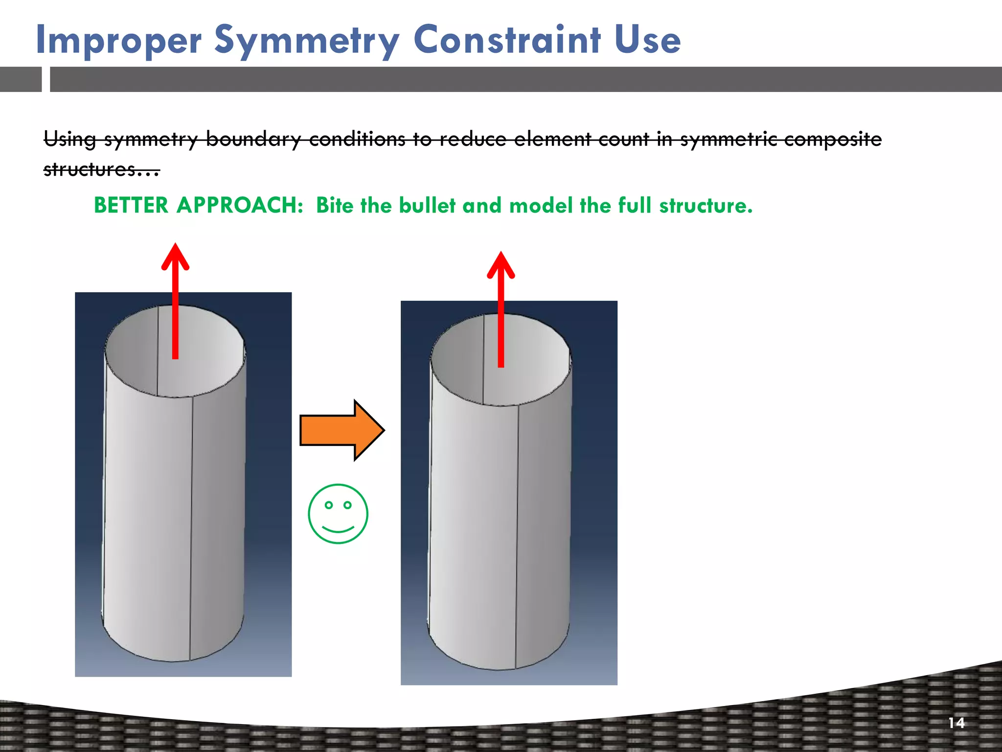
Using symmetry boundary conditions to reduce element count in symmetric composite
structures…
Example:
Use symmetry boundary
conditions to model ¼ of an
axially loaded [30/-30/90]3
tube meshed with 1 element per
ply.
The 30° plies want to shear as
they are axially pulled. By
constraining these plies with
symmetric boundary
conditions, artificial stress
concentrations are generated.
13](https://image.slidesharecdn.com/sampermfallworkshop2012-120923063417-phpapp02/75/Finite-Element-Analysis-of-Composites-by-Dan-Milligan-13-2048.jpg)


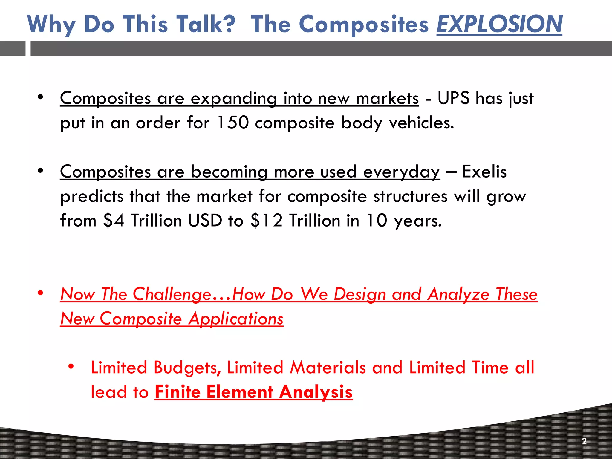
The document outlines a workshop presented by Dan Milligan on finite element analysis (FEA) of composite materials, highlighting the growth of the composites market and the importance of accurate design and analysis techniques. Key topics covered include recommendations for finite element modeling, methods for determining composite failure, and the necessity of 3D analysis for accurate predictions of composite failure. The presentation also discusses common pitfalls in FEA and suggests strategies for improving modeling techniques.
Introduction to composites market growth and the importance of FEA in design and analysis.
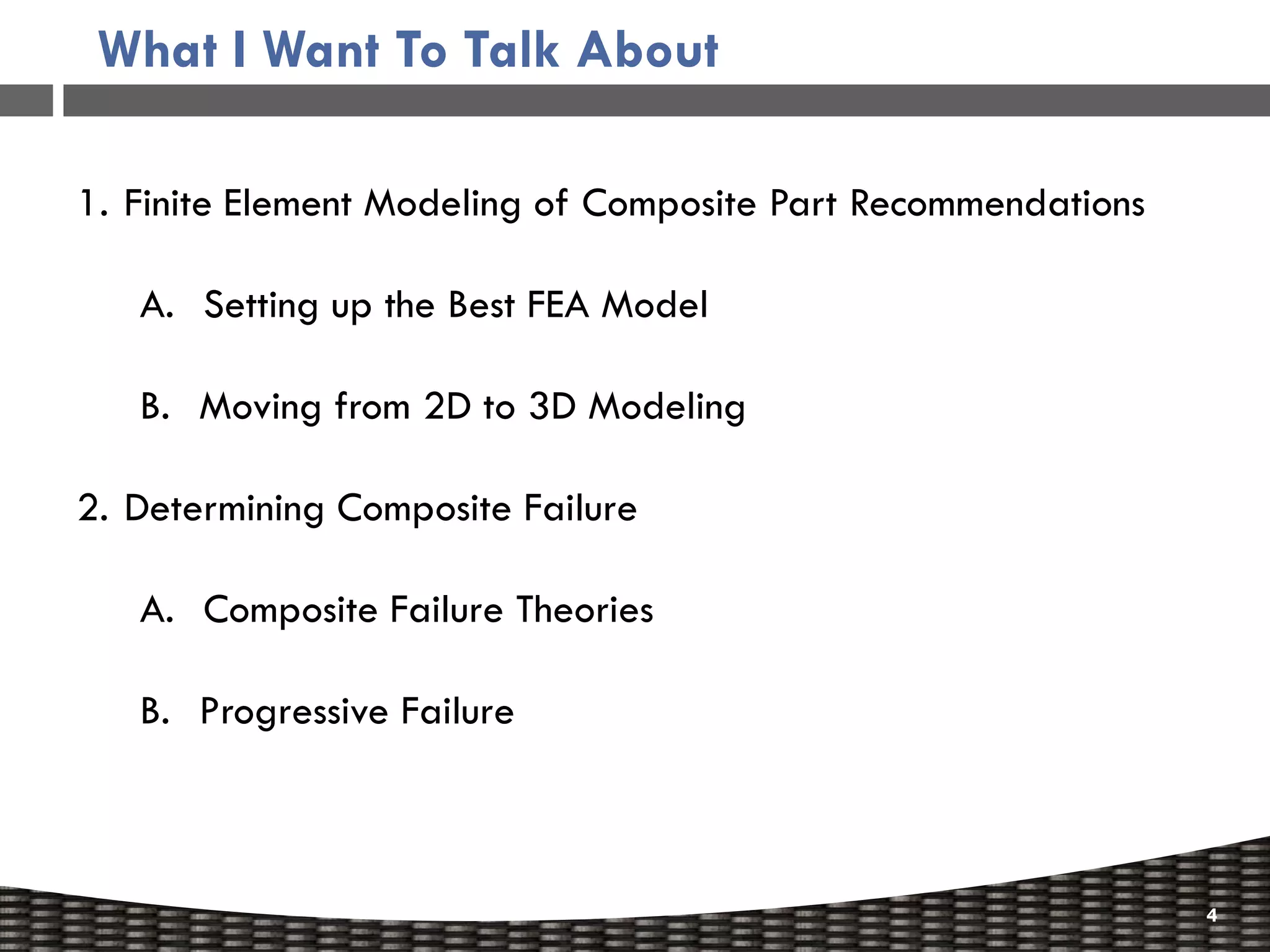
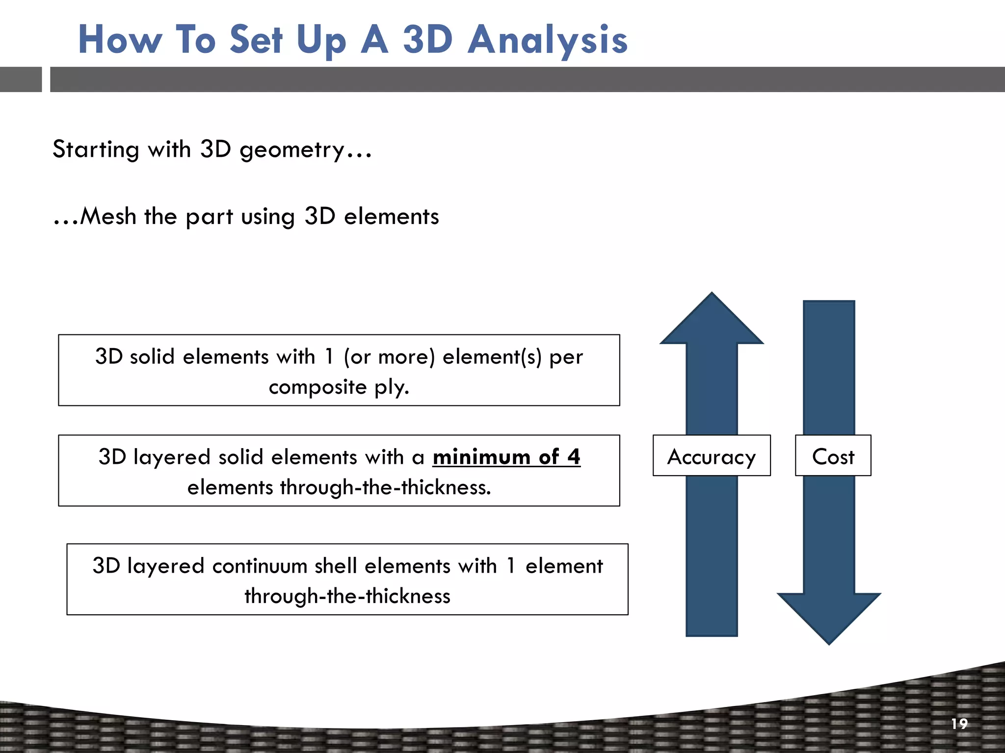
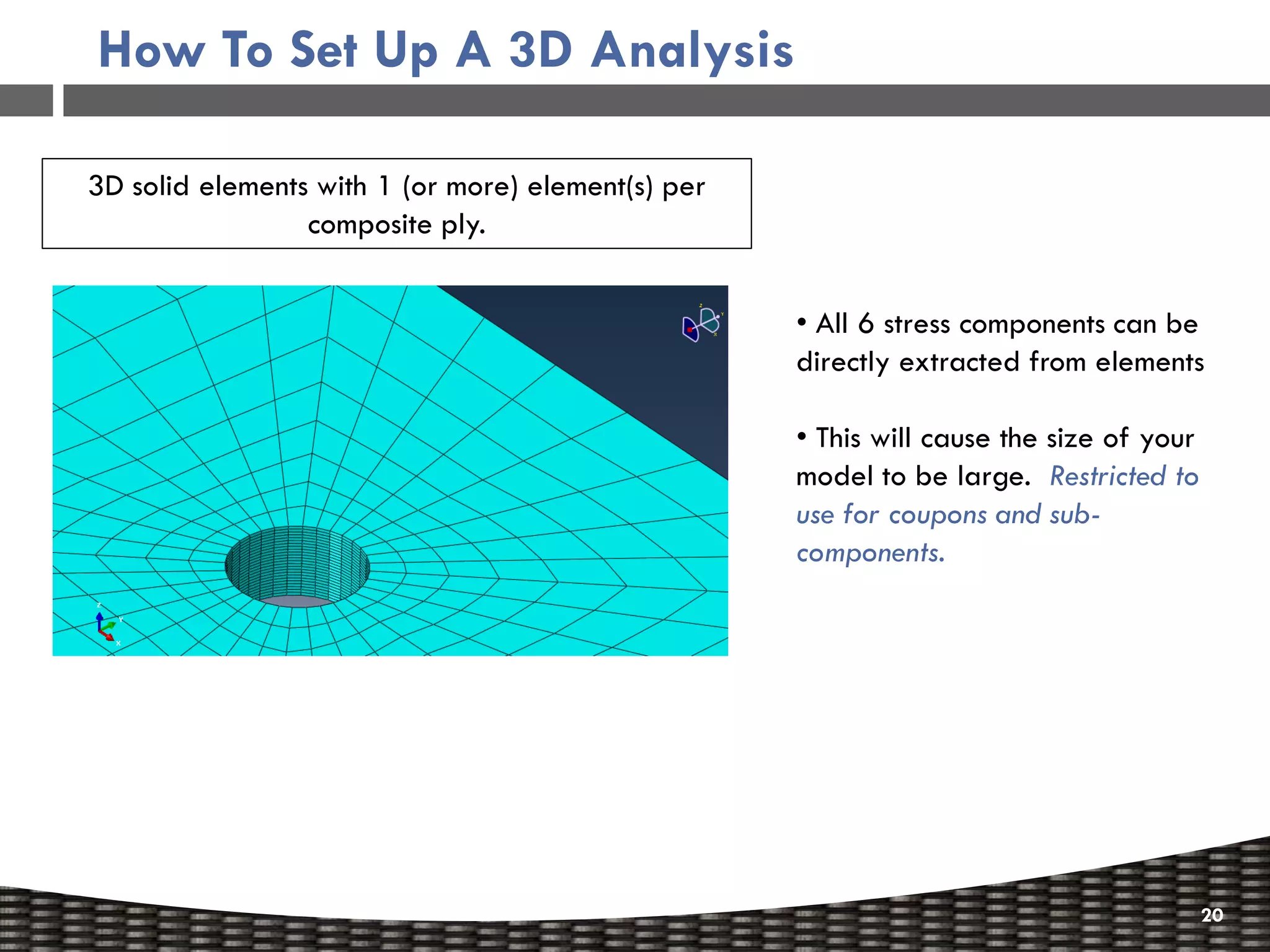
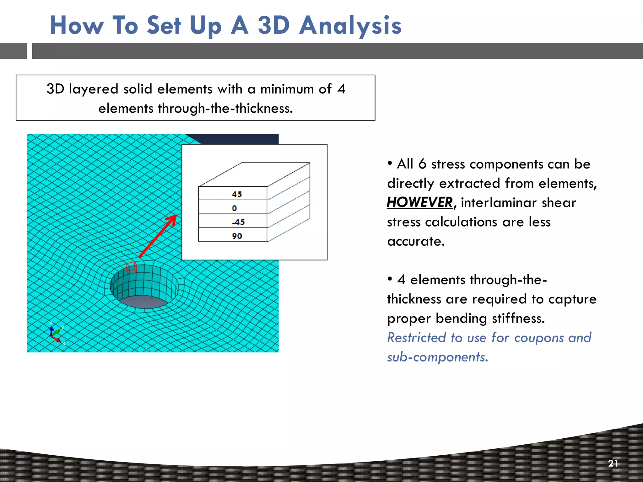
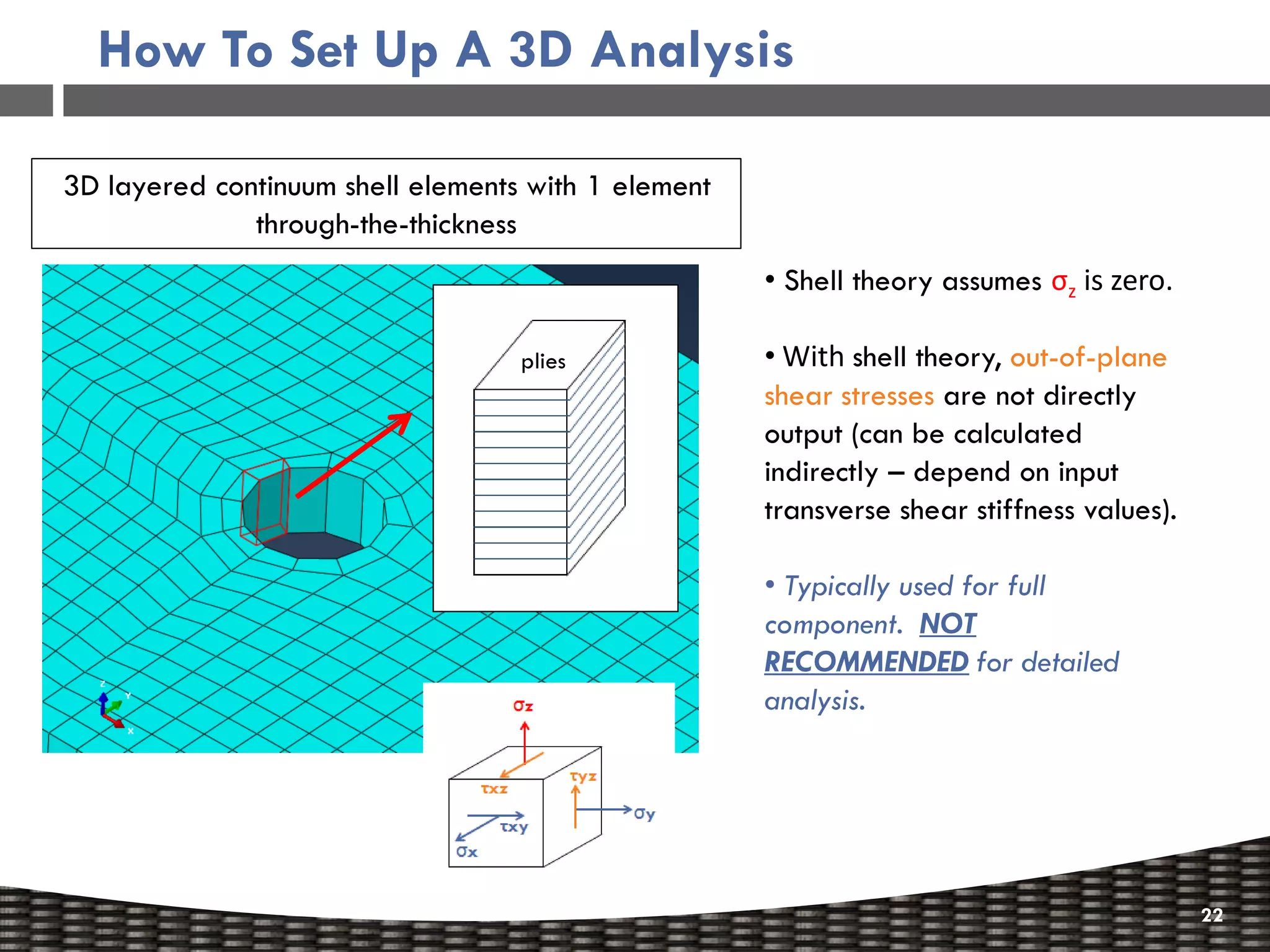
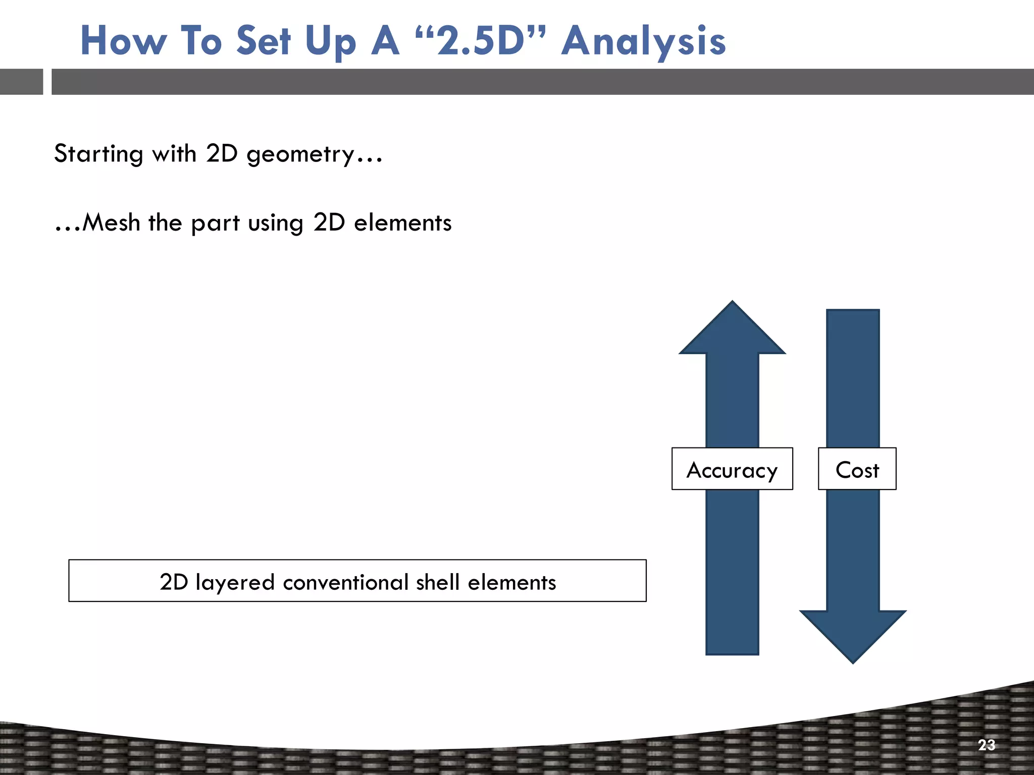
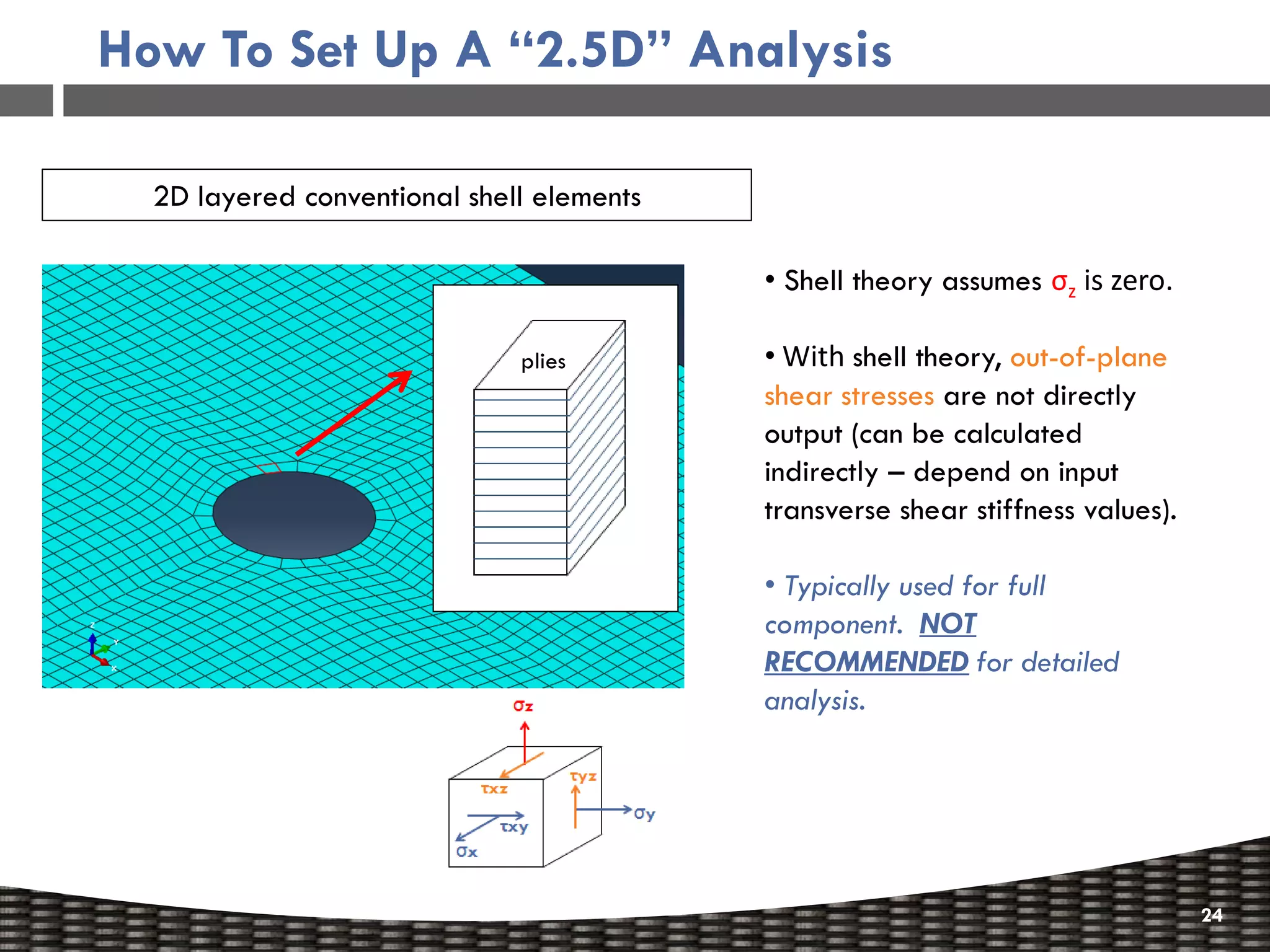
Discusses FEA model recommendations, including 2D to 3D modeling transitions.
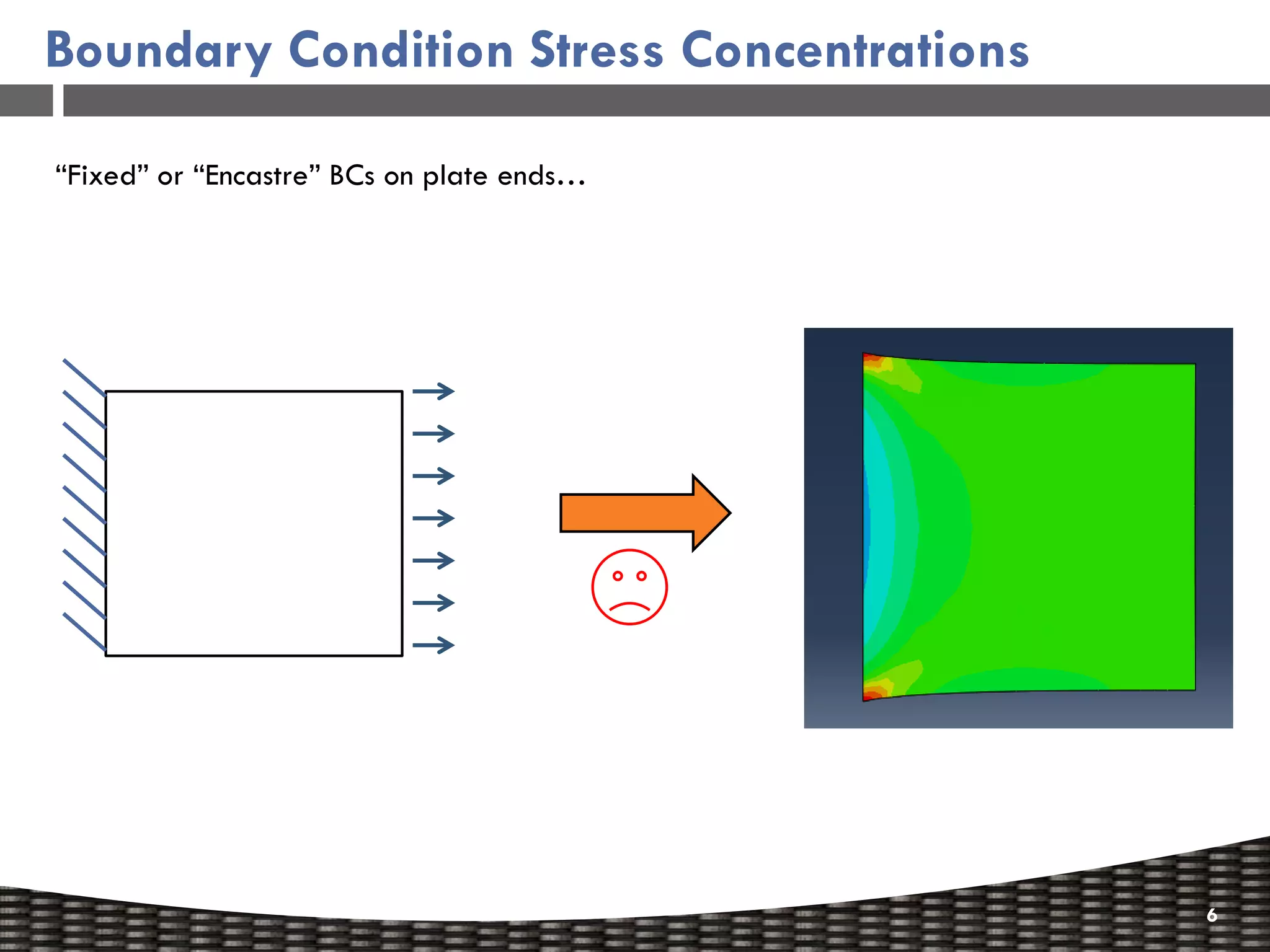
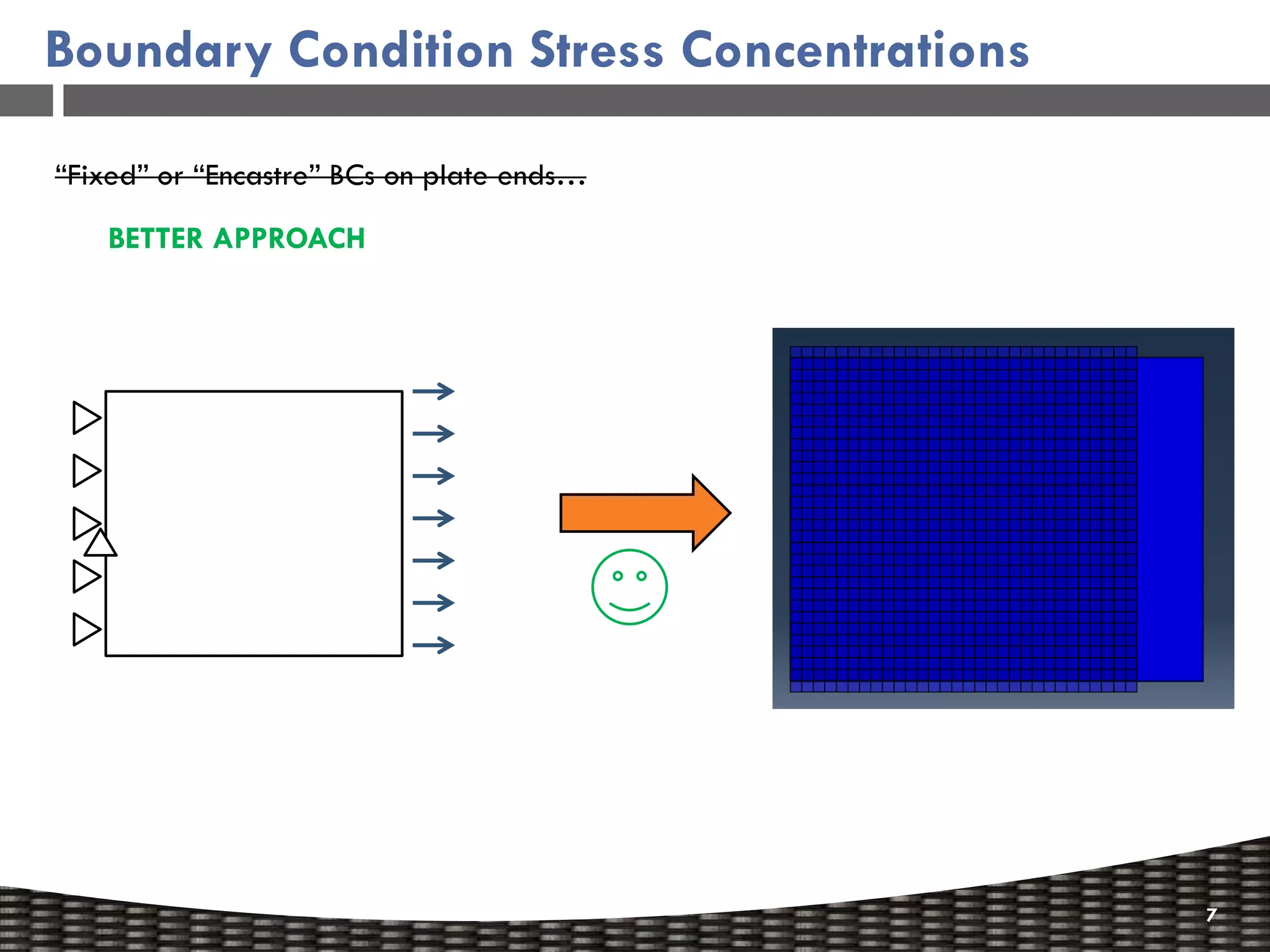
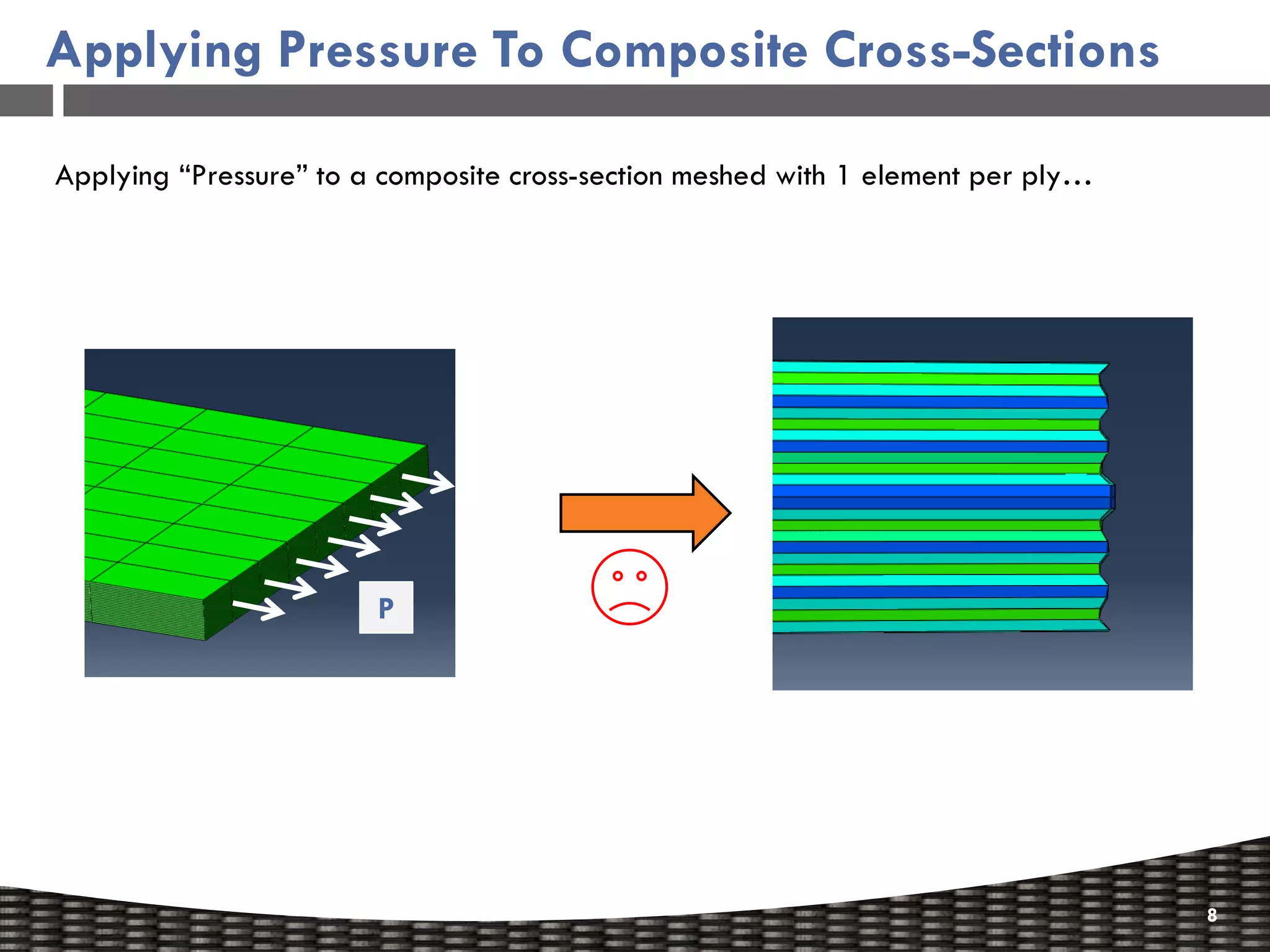
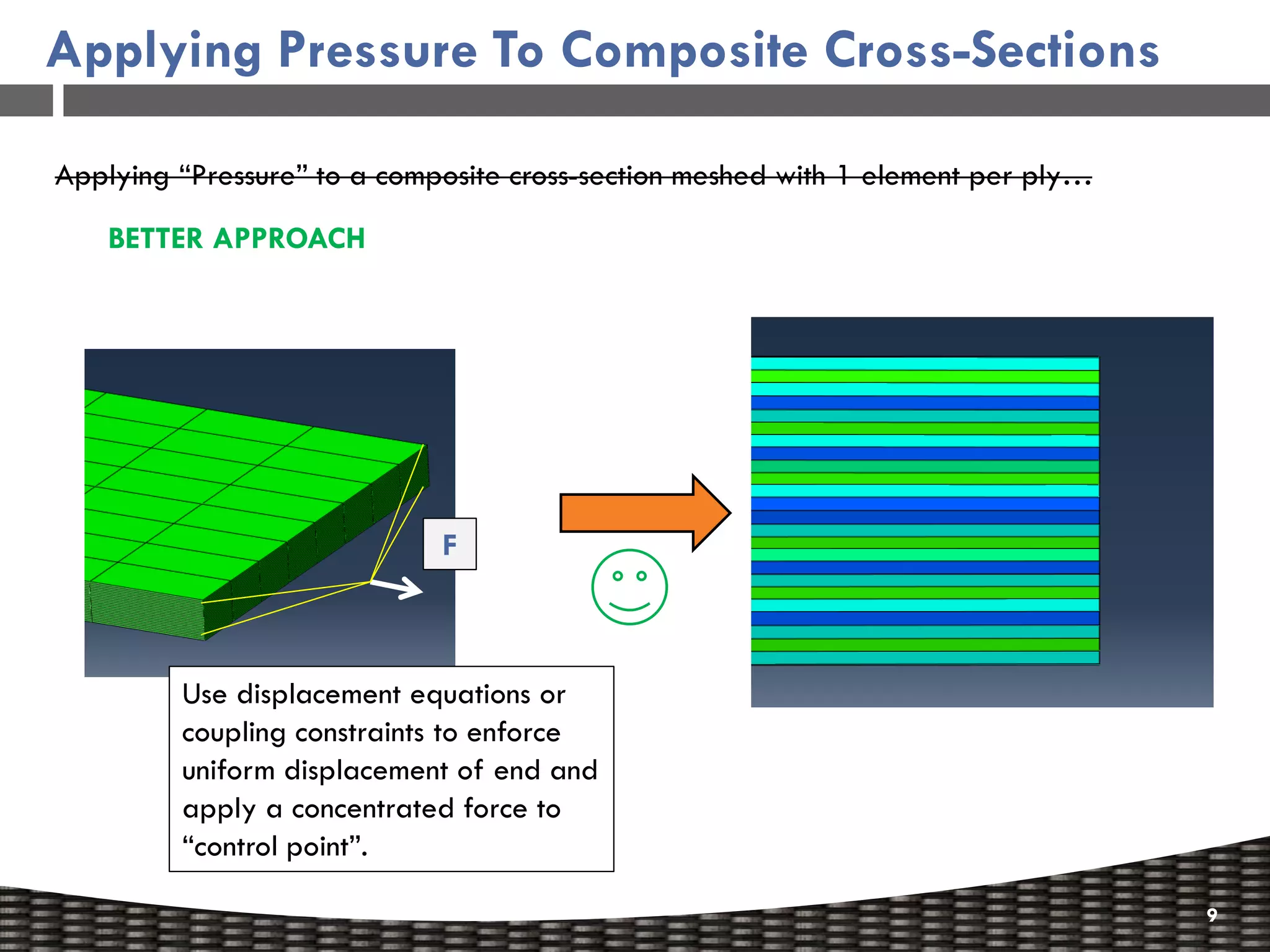
Focus on stress concentrations and better approaches for applying pressure in composite cross-sections.
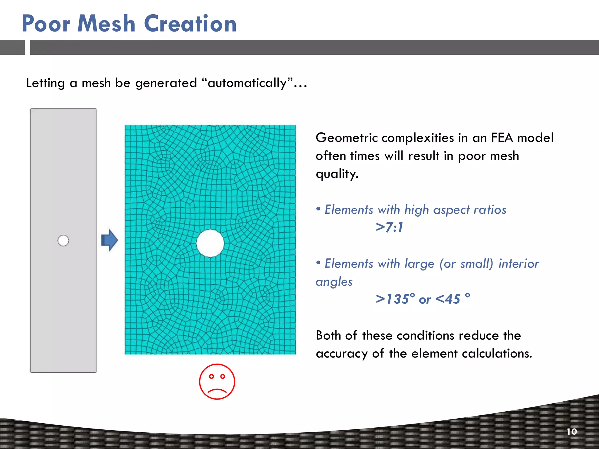
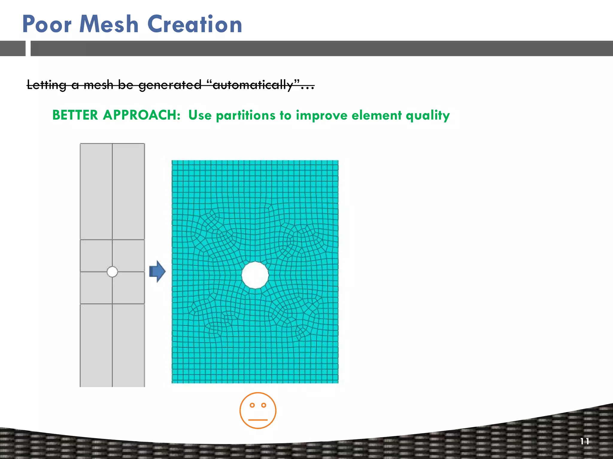
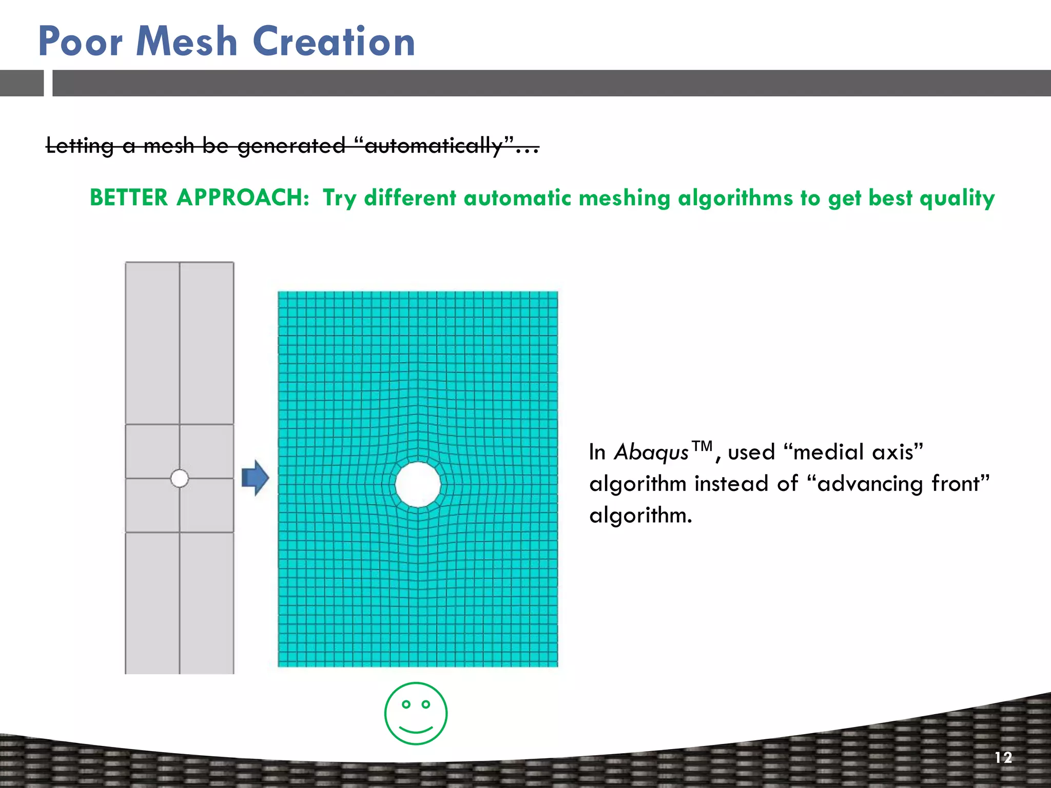
Highlights common mesh creation problems and better approaches for improving element quality.
Explains the pitfalls of improper symmetry constraints and recommends full structure modeling.
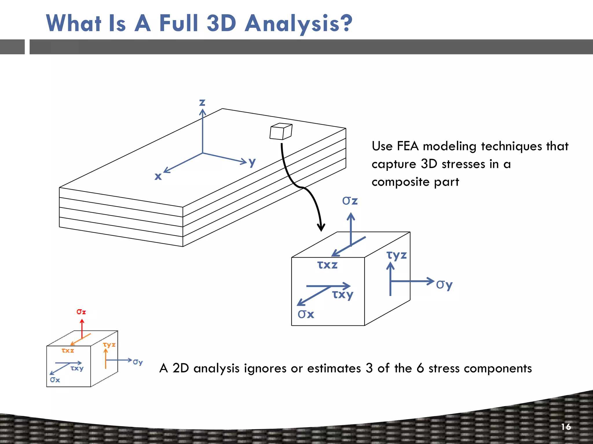
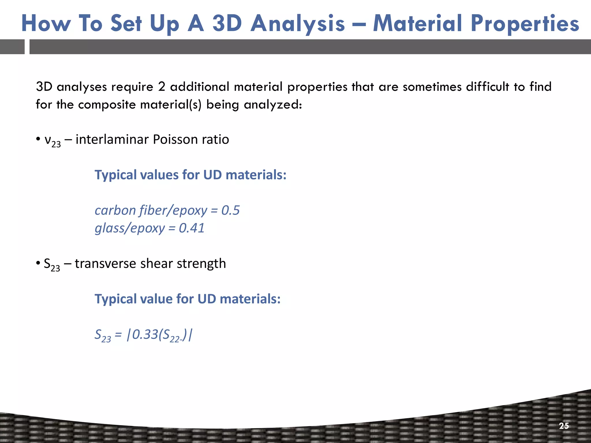
Emphasizes the need for full 3D analysis to accurately predict stresses and failure in composites.
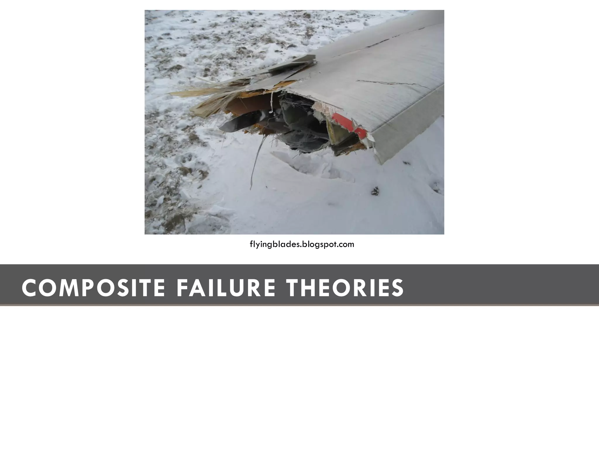
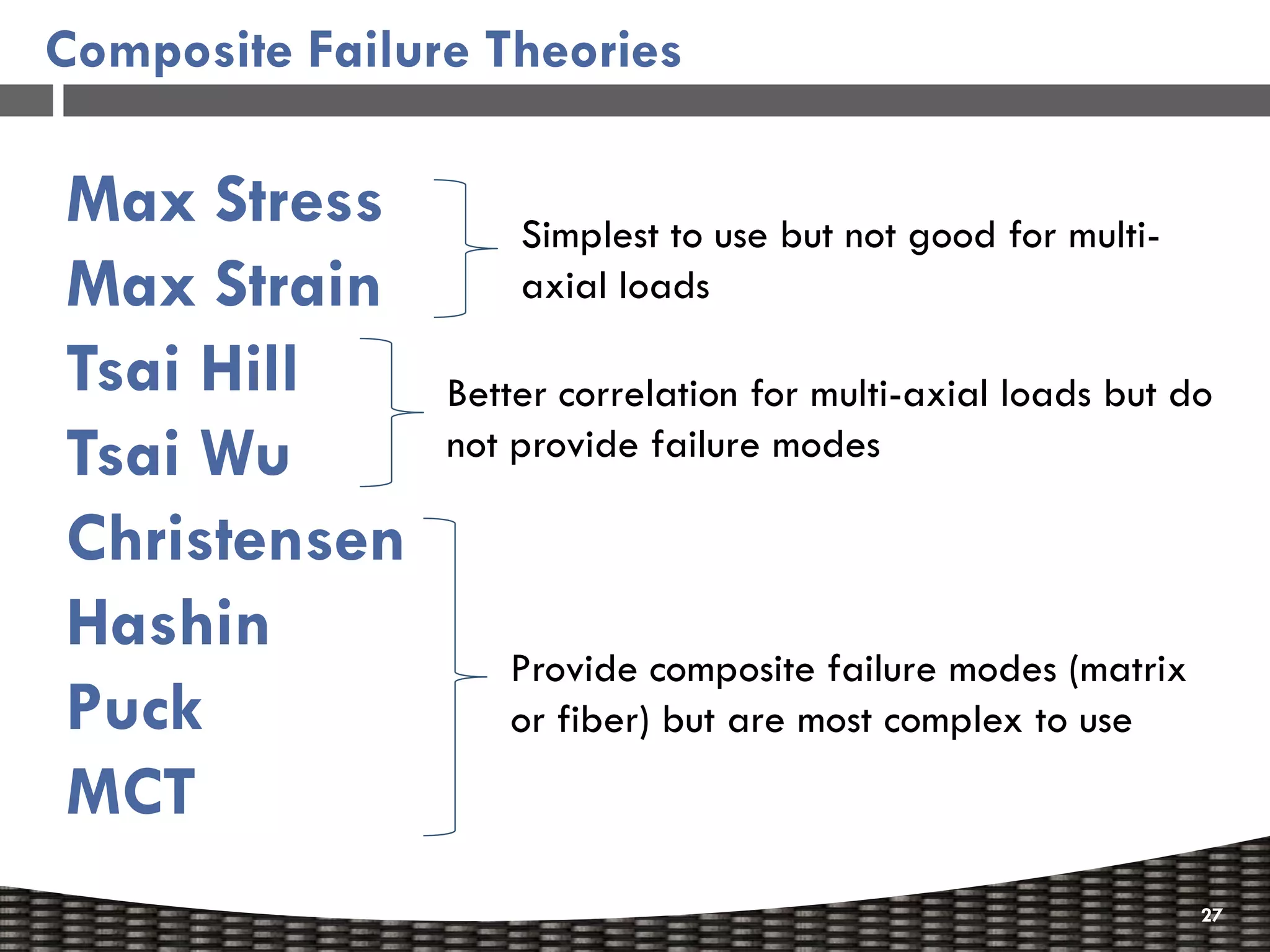
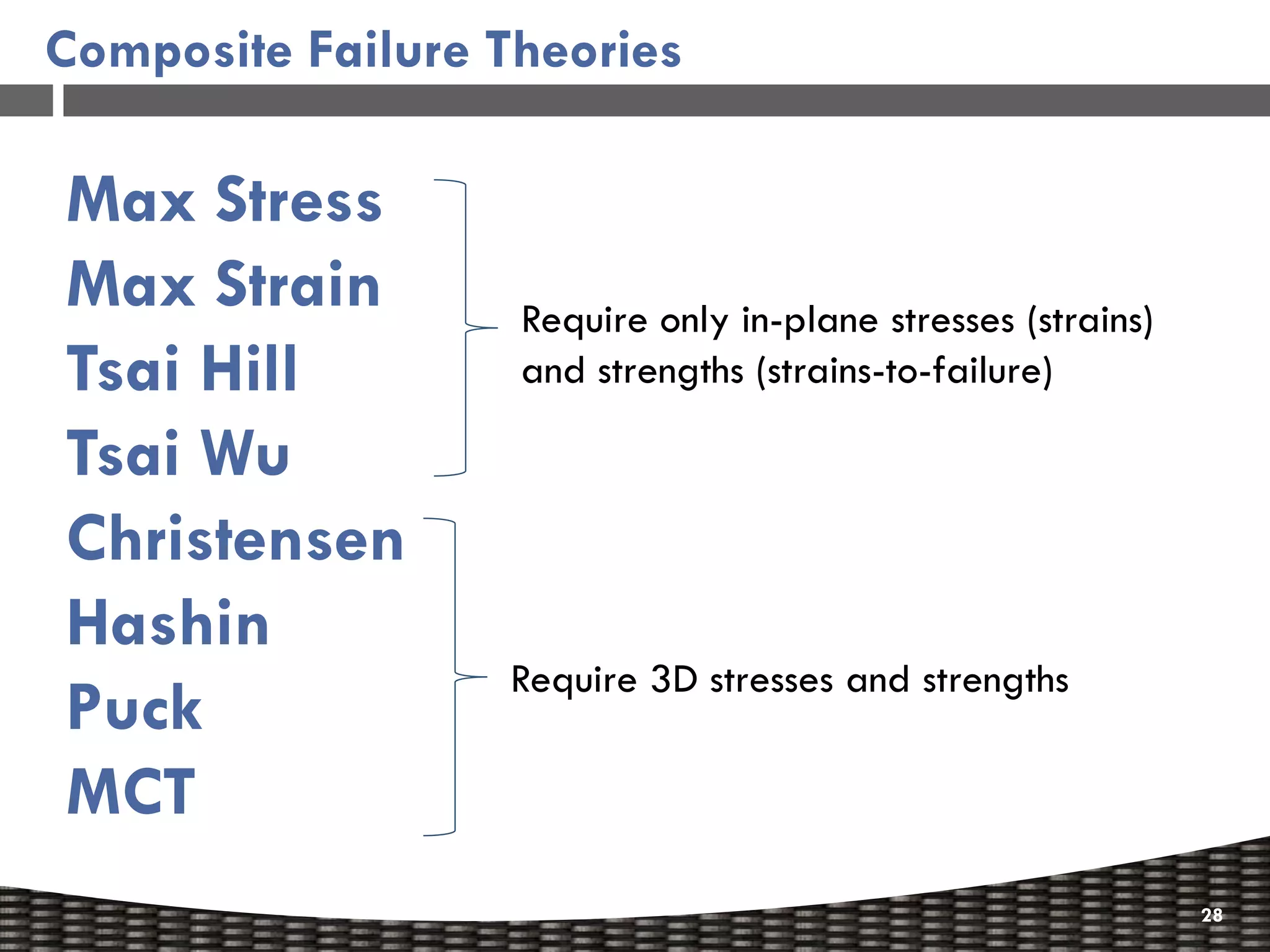
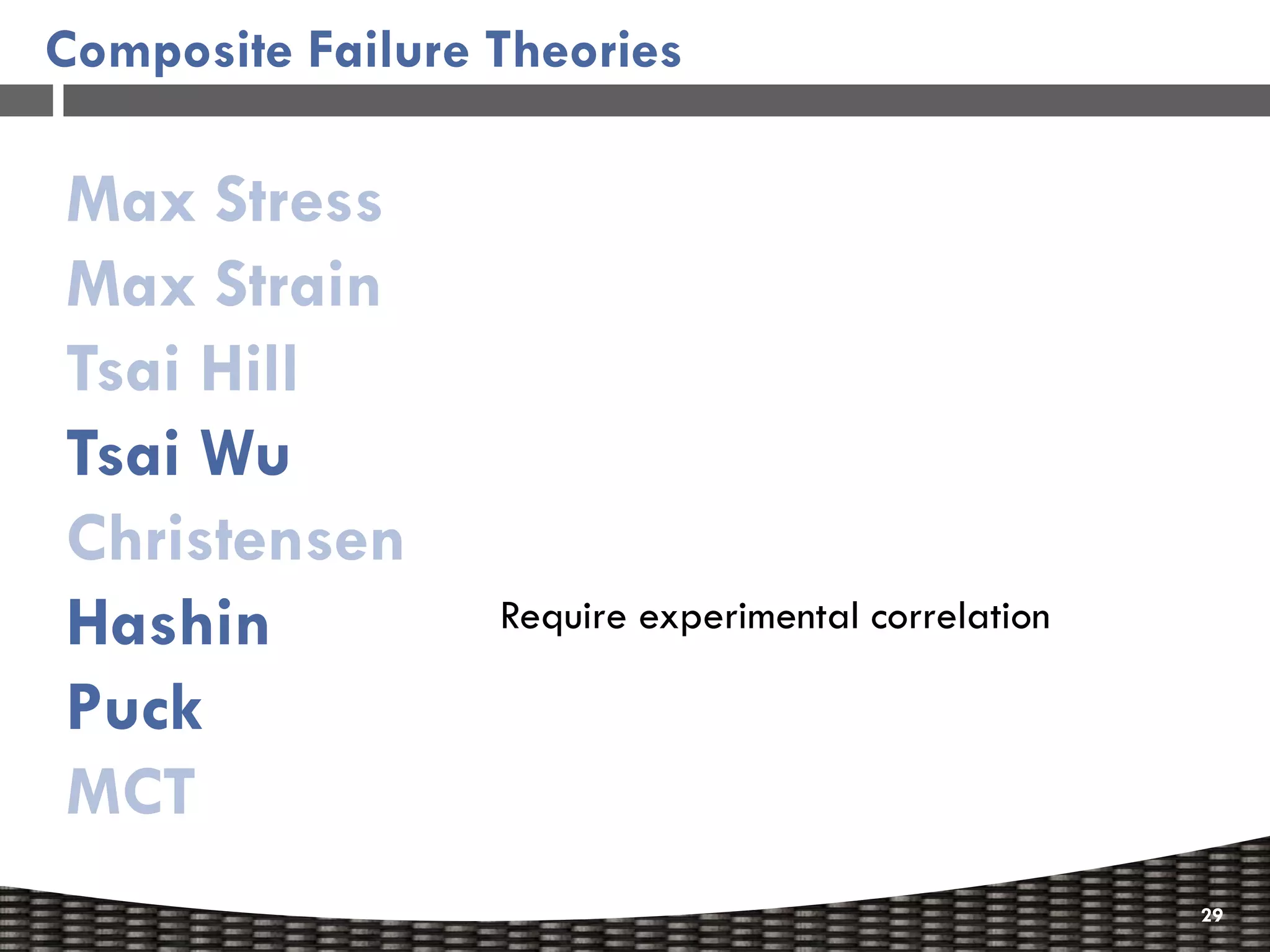
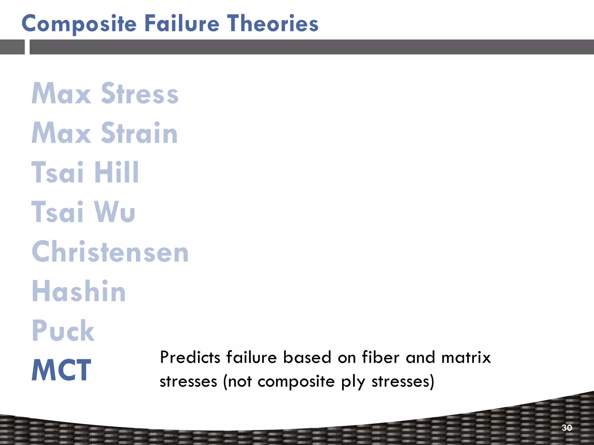
Overview of various composite failure theories and their applicability in different loading scenarios.
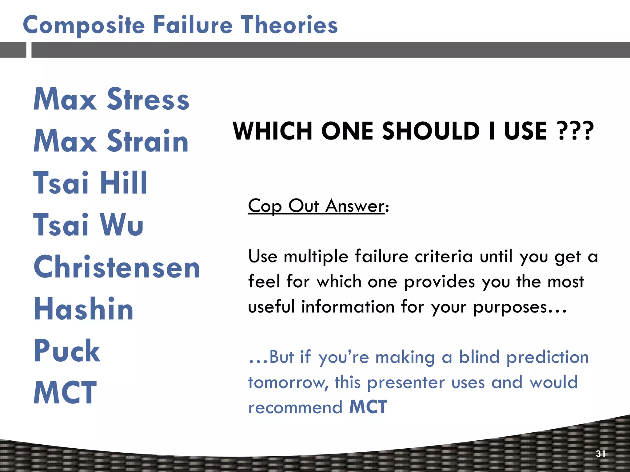
Advice on selecting appropriate failure criteria for composite analysis.
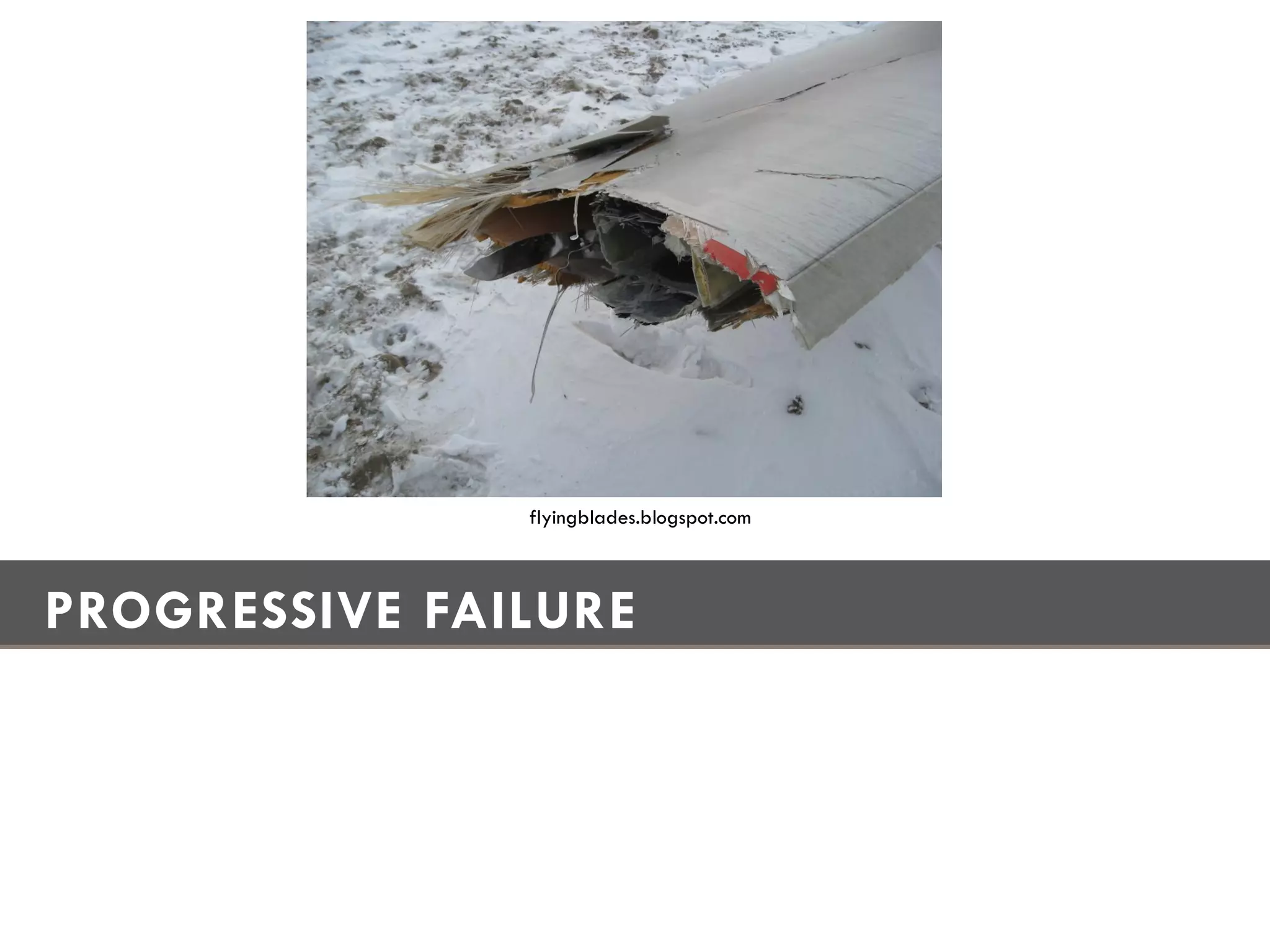
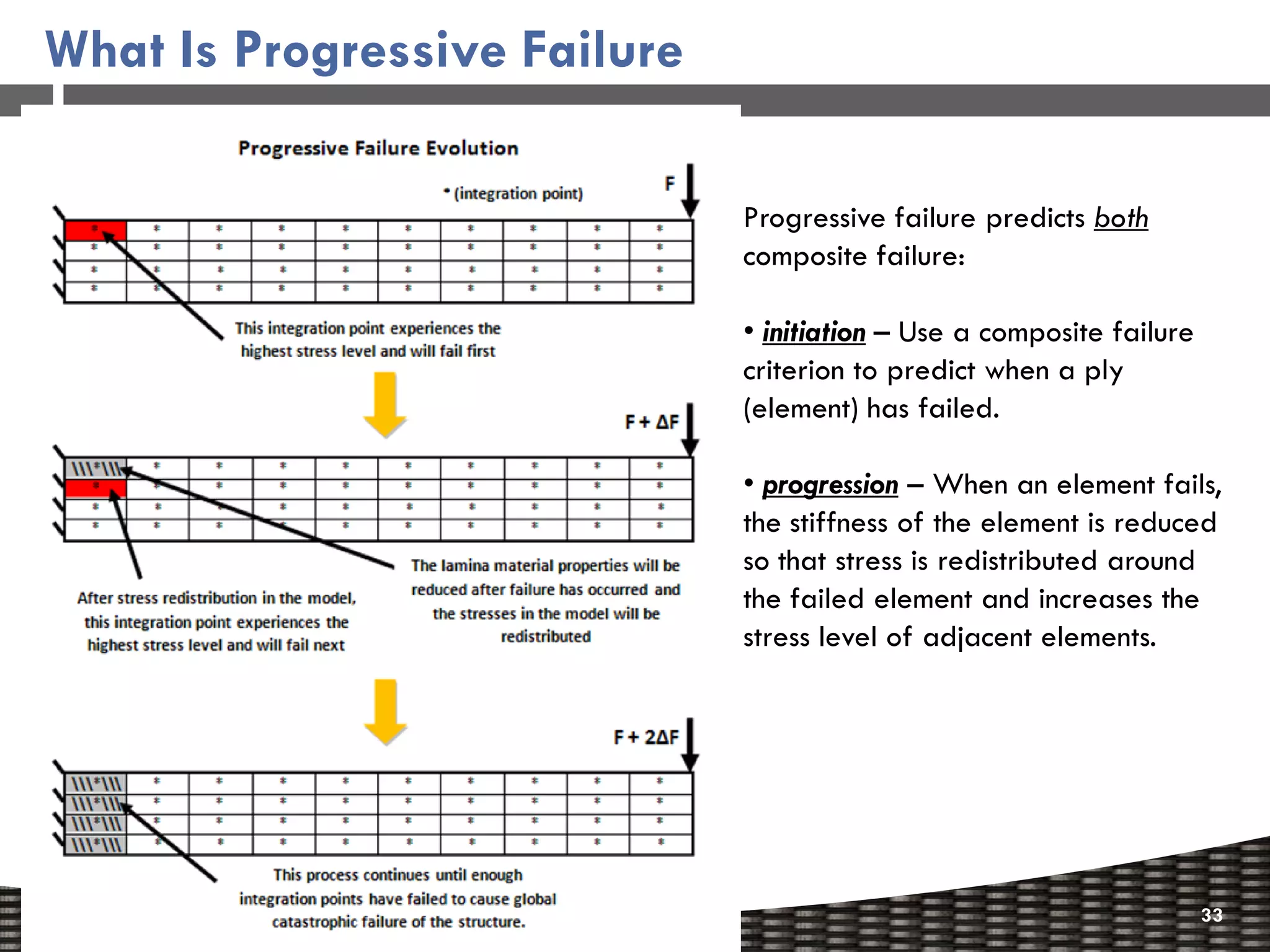
Introduction to progressive failure, predicting initiation and progression of composite failures.
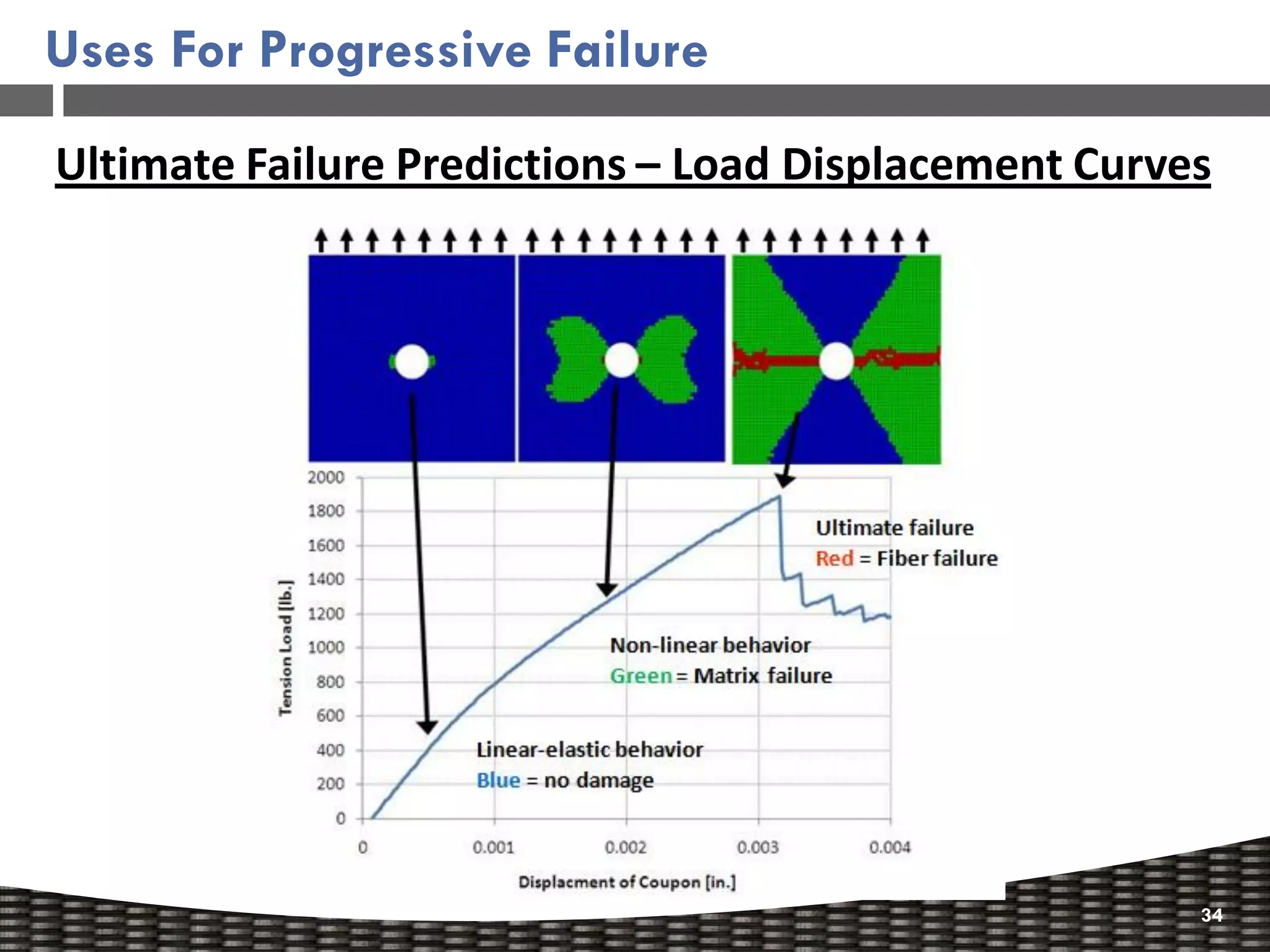
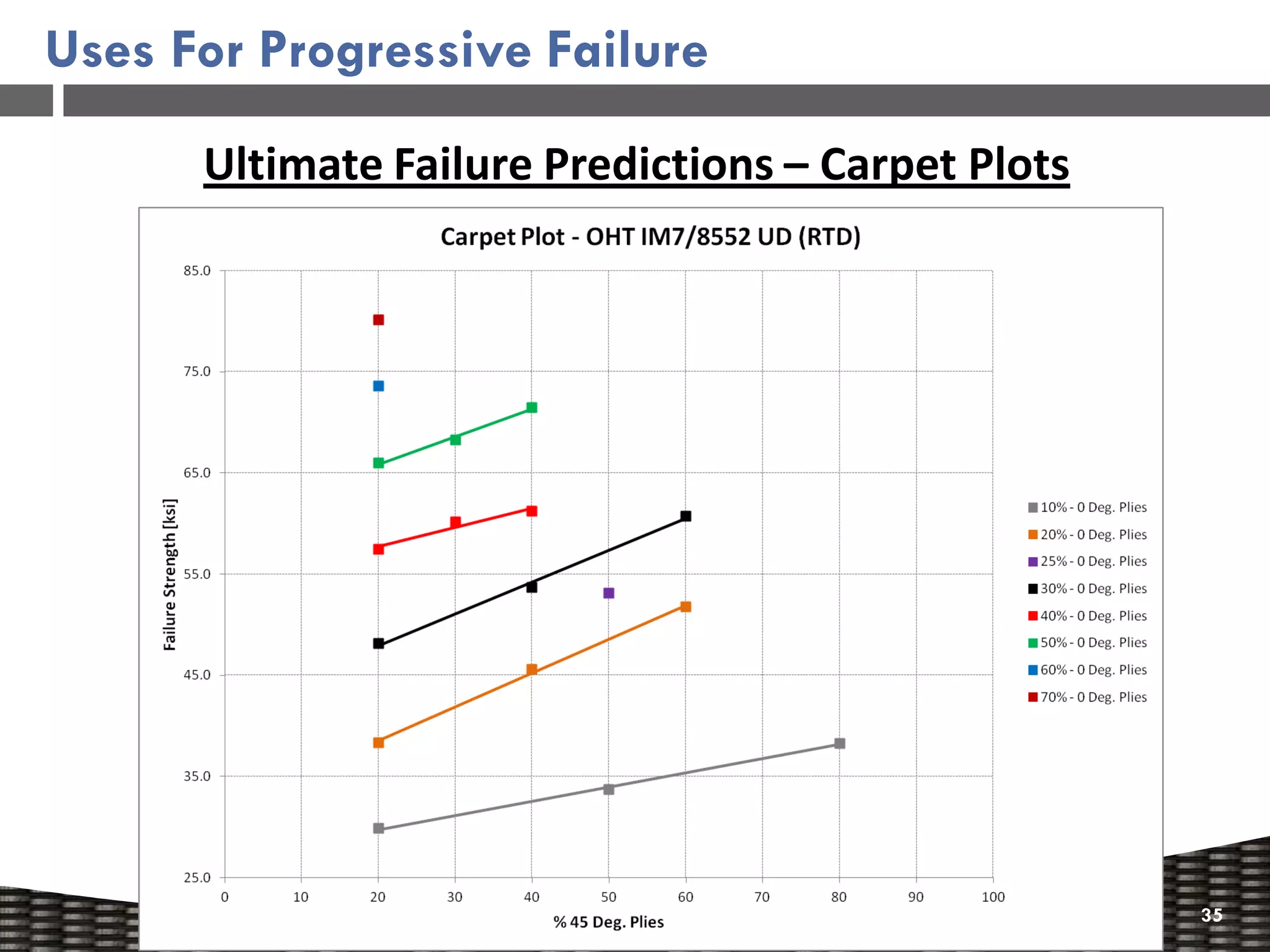
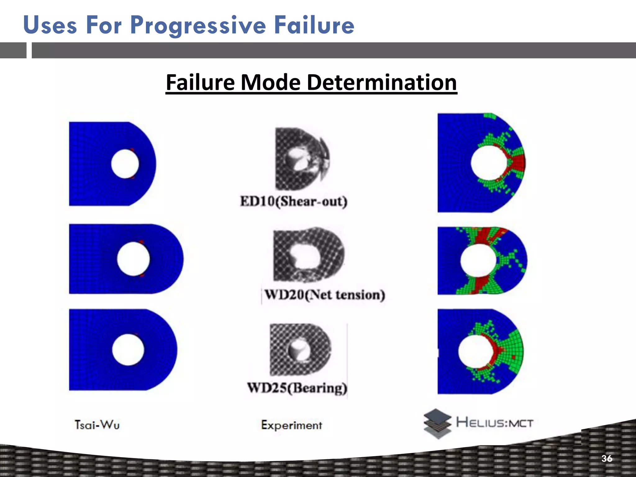
Discusses uses of progressive failure analysis for ultimate failure predictions and mode determination.
Wrap-up of the presentation with an invitation to connect for further discussion.


![[BDD 2025 - Full-Stack Development] Digital Accessibility: Why Developers nee...](https://cdn.slidesharecdn.com/ss_thumbnails/fs-digitalaccessibilitywhydevelopersneedtoknowandcarein2025-251127011019-0674441d-thumbnail.jpg?width=640&height=640&fit=bounds)


![[BDD 2025 - Mobile Development] Exploring Apple’s On-Device FoundationModels](https://cdn.slidesharecdn.com/ss_thumbnails/md-exploringappleson-devicefoundationmodels-251124030840-d690542c-thumbnail.jpg?width=640&height=640&fit=bounds)


![[BDD 2025 - Full-Stack Development] Agentic AI Architecture: Redefining Syste...](https://cdn.slidesharecdn.com/ss_thumbnails/fs-agenticaiarchitectureredefiningsystemcommunication-251124030838-e6c70cc2-thumbnail.jpg?width=640&height=640&fit=bounds)

![[BDD 2025 - Full-Stack Development] PHP in AI Age: The Laravel Way. (Rizqy Hi...](https://cdn.slidesharecdn.com/ss_thumbnails/fs-phpinaiagethelaravelway-251125012602-ef9d330e-thumbnail.jpg?width=640&height=640&fit=bounds)

![[BDD 2025 - Artificial Intelligence] AI for the Underdogs: Innovation for Sma...](https://cdn.slidesharecdn.com/ss_thumbnails/ai-aifortheunderdogsinnovationforsmallbusinesses-251124030839-72a599a4-thumbnail.jpg?width=640&height=640&fit=bounds)
