SlideShare a Scribd company logo
1 4 U S E R M A N U A L
1 0 1
w w w . c o n s t e e l s o f t w a r e . c o m
Read out the parameter of an existing member by clicking on it and assigning those
parameters to the one to be created
Member parameters can be defined in the middle part of the dialog:
Section: before creating a beam or column member the cross-sections should be loaded,
and the appropriate section can be selected from the combo including the loaded
sections. If no section has been loaded in advance the SECTION dialogue can be called by
pressing the three dots button ( ) next to the combo. For more information about
section administration see the next chapters. See Chapter 10 for details on the section
models and standard tests used in Consteel.
Release (start, end): predefined releases can be assigned to the ends of the members. If
new release type is needed the RELEASE dialogue can be called by pressing the button
next to the combo.
1 4 U S E R M A N U A L
1 0 2
w w w . c o n s t e e l s o f t w a r e . c o m
Initial bow imp.: half-sine wave shaped initial crookedness can be defined in the two local
direction perpendicular to the member reference axis (“y,z”) with the given amplitude at
the mid-length.
Element type:
Section made from steel:
Two choices are possible Beam-column with warping and Tension bar,
these types influence the finite element type used in the analysis. The
beam-column with warping is a special element with 14 degree of freedom, including the
warping of the thin-walled cross section. It is an important effect in case of structures with
standard, open steel profiles.
The tension bar can only resist tensional axial force (no bending or torsional moments and
shear) if it got compression the analysis neglects its effect.
Reinforce concrete or Composite sections:
There is only one choice, the General beam-column type this is
the commonly used 12 degree of freedom finite element.
Element group: the members can be sorted out into element
groups for various purposes (selection, dominant results,
sensitivity analysis etc.).
if new element group is needed the GROUPS OF STRUCTURAL MEMBERS dialogue can
be called by pressing the button next to the combo.
Number of finite elements: the required number of finite elements used
on the member in the analysis can be set. The default automatic option
gives a sufficient result in the most cases.
Local eccentricity: member eccentricity can be defined in the local coordinate system (“y,
z”) of the member, and the section can be rotated about the local coordinate “x”.
At the bottom of this dialog there is an instruction and command area for guiding the
user.
IT SHOULD BE NOTED THAT NOT ONLY THE ECCENTRIC AXIAL FORCE PRODUCES INFLUENCE IN THE
ANALYSIS (ADDITIONAL BENDING MOMENTS) BUT THE ECCENTRIC BENDING AND TORSIONAL
MOMENTS (ADDITIONAL BENDING AND TORSIONAL MOMENTS AND BIMOMENT)!
5.2.1. STEEL MEMBERS
As the first step of line member modelling, cross sections must be loaded into the model.
This can be performed either from the SECTION ADMINISTRATOR directly, either from the
BEAM dialogue. In Consteel 13, in addition to the cross-sections in the standard section
database and the macro section, it also allows you to load drawn (unique) sections.
1 4 U S E R M A N U A L
1 0 3
w w w . c o n s t e e l s o f t w a r e . c o m
It is important to note that in Consteel, material quality is an attribute of the cross-
section, therefore it must be defined when loading the cross-section!
5.2.1.1. CROSS SECTION LIBRARIES
In CONSTEEL 13, the following standard cross section libraries are available:
Standard (European) cross section library
American section library (metric and imperial)
British section library
Chinese section library
Russian section library
Manufacturers 'profiles (catalogues of individual manufacturers' profiles)
5.2.1.2. MACRO SECTIONS
In CONSTEEL 13, the following macro sections are available in 4 groups:
1) Sheet welded types
Welded I or H section
Welded box section
Welded Maltese cross section
Welded half Maltese cross section
Welded hat section
Welded T
WQ section
Slant flange welded I or H section
C section
2) Hot rolled types
1 4 U S E R M A N U A L
1 0 4
w w w . c o n s t e e l s o f t w a r e . c o m
Rolled I or H shape (with parallel flange)
Rolled angle (parallel leg)
Rolled channel (parallel flange)
CHS shape
T shape (half I)
Plate
Round bar
RHS
3) Cold-formed types
RHS
CHS
L profile
unsymmetrical U section
Z shape
C shape
Sigma section
Zeta section
Slope omega section
In the case of cold-formed macros, it is also possible
to provide stiffeners for the last 5 profile types. On the
flanges once or twice bent edge stiffeners, and two
different types of intermediate stiffeners can be
defined. On the webs three different types of
intermediate stiffeners can be defined. In the case of
web stiffeners, it is also possible to double the
stiffeners. The stiffeners defined this way are taken
into account in the calculation of distortional buckling as defined in EN 1993-1-3.
1 4 U S E R M A N U A L
1 0 5
w w w . c o n s t e e l s o f t w a r e . c o m
For cold formed macro sections, if they are made of coated material, the thickness tolerance
category as defined in EN 10143 shall also be provided. There are two categories: normal and
special. Accordingly, the design wall thickness of the cross section is calculated according to
EN 1993-1-3 section 3.2.4. In general
construction practice, such sections are most
often made of coated steel sheets according to
the aforementioned EN 10143 standard, and
therefore these macros are based on the thickness tolerance categories defined in this
standard.
IMPORTANT, THAT IF THE DESIGNER DOES NOT CHOSE THE COATED MATERIAL FROM THE
DATABASE AND THAT THE SELECTED MATERIAL HAS A THICKNESS TOLERANCE MORE THAN 5%,
IN THIS CASE THE CALCULATION WILL NOT BE EXACT. TO AVOID THIS, YOU MUST IMPORT THE
CROSS SECTION INTO THE SECTION DRAWER MODULE AND PROVIDE THE REAL THICKNESS
TOLERANCE. (THE SECTION DRAWER SEE IN THE FOLLOWING CHAPTER!)
4) Compound types
I or H shape reinforced by channel at one flange
I or H shape reinforced by channels at both flanges
I or H shape reinforced by half I or H
I or H shape reinforced by half I or H shapes at web
1 4 U S E R M A N U A L
1 0 6
w w w . c o n s t e e l s o f t w a r e . c o m
I or H shape reinforced by angels at flange
I or H shape reinforced by plates at flanges
I or H shape reinforced by I or H shape at flange
Closed shape with angles and plates
Closed 2U
Closed 2I
I plus U
I from 2U
Half Maltese
Battened section
5.2.1.3. SECTION DRAWER
In Consteel 13, the third option for creating a section is section drawing in the SECTION
DRAFTER module. The function can be started by pressing the DRAW SECTION button in the
SECTION ADMINISTRATION dialog box.
As a first step, after the command has been executed, you will need to select a section type
and material quality in a pop-up window and enter the section name. There are two types of
cross-sections:
Cold formed section
General thin-walled section
The type of cross section has a fundamental influence on its later operation. With a cold
formed section, you can create sections with only one line, which have a uniform wall
thickness, automatically create a curve between segments, and cannot be closed. In addition
to the strength, local and global stability tests, the program also takes into account the
effective cross-sectional reduction due to distortional buckling, in accordance with EN 1993-
1-3.
In the case of general thin-walled sections, sheets of different thicknesses may be used, the
section need not be drawn on a single line, and single-closed sections may also be made. This
type is basically used to create sheet welded sections. For these sections, only strength, local
and global stability tests can be performed.
After selecting the segment type, clicking on the NEXT button opens a separate window for
the SECTION DRAFTER MODULE, the contents of which are slightly different depending on
the type of section you choose.
The profile drawing window is structured as follows:
1 4 U S E R M A N U A L
1 0 7
w w w . c o n s t e e l s o f t w a r e . c o m
1# Drawing Area
2# Commands
3# Diagnostic Messages: Displays various warning and error messages
4# Navigation: Use the BACK and NEXT buttons to move between the different phases
of the section drawing
5# User Interface Settings: There are four tabs on the pop-up window that provide
parameters and switches for adjusting the VISIBILITY, GRID, SNAP, and OBJECT SIZES.
6# Specify Parameters: always displays parameter panels for the current function and the
selected item.
5.2.1.3.1. DRAWING OF COLD FORMED SECTIONS
Cold formed sections are defined in 4 phases.
(1) Drawing of the geometry
(2) Specify design parameters for strength and global stability tests
(3) Specify design parameters for local buckling tests
(4) Defining stiffeners
(1) Drawing of the geometry
The section geometry is edited in the first phase. Stiffeners can be easily and quickly drawn
using macros. It is also possible to import a previously loaded cross section.
1
Q
2
3
4
5
6
1 4 U S E R M A N U A L
1 0 8
w w w . c o n s t e e l s o f t w a r e . c o m
DRAW POLYLINE shortcut to start editing geometry. Drawing can also be done by
selecting endpoints in the drawing space or by entering coordinates in the DRAW LINE pop-
up window. Coordinates can be specified in Cartesian or Polar coordinates, local
or global . In the case of local input, the coordinate system is rotated according to the grid
angle, in the case of global input the coordinate system does not change. The positioning of
the plate segments relative to the drawn reference line (offset) can be centered,
left, or right aligned. You can change this during drawing or later, one by one, in the PLATE
SEGMENT PARAMETERS panel on the sidebar. Roundings are created automatically when you
draw plate segments. The radius of roundings can be modified subsequently, by selecting the
curvature, individually in the sidebar, or uniformly over the entire section. You can also enter
the nominal sheet thickness here.
In the section drawing window, after typing each parameter, you must also press
ENTER for the entered value to take effect!
You can continue drawing plate segments only from one endpoint. When you have finished
drawing, you can exit the command by pressing the ESC key or by clicking the EXIT button. If
you want to edit the drawing, you can delete and redraw that section to fix the problem.
1 4 U S E R M A N U A L
1 0 9
w w w . c o n s t e e l s o f t w a r e . c o m
The following two commands will launch the INTERMEDIATE STIFFENER and
EDGE STIFFENER macros. There are three types of intermediate stiffeners and two types of
edge stiffeners. A panel for specifying the geometry parameters of the stiffener appears in the
right sidebar. You can also specify which side of the segment the stiffener have to be placed.
After the command is executed, pointing to a plate segment with the cursor, the stiffener
corresponding to the set parameters appears. After adjusting the parameters, you can place
the stiffener by clicking on the desired location. After positioning, by selecting the stiffener,
the parameters, and in case of intermediate stiffeners the positions remain adjustable. Note
that these commands are just macros to make the drawing process easier. The plate segments
drawn in this way, only after defining in Phase 4, actually become code compliant stiffeners.
With the IMPORT SECTION command, you can import and further edit a previously
created library, macro, or drawn section. Obviously, only a cold formed, one-line drawing can
be imported. After the command has been issued, a window will pop up showing the sections
that are suitable for importing. Pressing the NEXT button loads the selected section. If you
have a previously drawn geometry, the program will warn you that current section you have
drawn so far will be deleted. The section imported retains all its geometry and design
parameters and remains editable.
The EXPLODE SECTION command converts the drawn stiffeners and roundings into
individual line and arc segments. After the exploding, also for these elements, only the
thickness and offset can be changed, not their size and position. By exploding, elements
previously defined as one segment, turn into separate segments whose classification can be
defined independently.
The PLACE DIMENSION command is used to apply dimension lines to each segment of
the section. There are two icons in the pop-up window that allow you to choose how to place
the dimension line:
Dimension Placement in Cartesian Coordinate System. You can specify
dimension lines in the Y or Z direction.
Placement of dimension line parallel to the line segment.
To place a dimension line, click on one of the line segments and click again to place the
dimension line in the desired position.
(2) Specify design parameters for strength and global stability tests
1 4 U S E R M A N U A L
1 1 0
w w w . c o n s t e e l s o f t w a r e . c o m
After the geometry has been drawn, the standard parameters required for the strength and
global stability analysis must be set.
In the first drop-down menu, you must choose the manufacturing type
of the cross section. It can be cold rolled, press broken or other cold
formed.
After that the thickness tolerance required to calculate the design wall
thickness and the number of the 90° bends must be entered. The
number of bends is automatically calculated when a macro profile is
imported. In the case of a drawn section, this field must be completed by
hand.
Next, the flexural and torsional buckling curves must be selected. If the
section is later used on a line member which is part of a PURLIN LINE
object, the lowest curve selected in the Lateral-torsional buckling for
purlin line field will be considered in the analysis.
(3) Specify design parameters for local buckling tests
Moving to the third phase, the drawing area displays the lengths of the segments used to
calculate effective length (bp). By selecting a segment, you can specify on the sidebar
whether, and in which direction, that segment should be considered in the calculation of the
shear buckling.
The following field specifies how the segment is to be
considered in the classification. There are three options to
choose from:
Automatic classification and efficient length calculation (default)
Ignore classification and consider total length
Ignore classification and do not consider the plate in the effective cross section
1 4 U S E R M A N U A L
1 1 1
w w w . c o n s t e e l s o f t w a r e . c o m
(4) Defining stiffeners
For the drawn stiffeners to be standard compliant stiffeners in
the calculation, they need to be defined at this phase. The first
step is to decide whether the section is cold-formed Z or C like
section or whether it is a general shape. You can choose by using
the radio buttons in the sidebar.
When choosing a Z or C like profile, the calculation takes into account the stress of the other
flange as well as the stiffness of the web when supporting the flange. To do this, of course,
you need to specify which parts of the section make up the lower and upper belts, and the
web, and you must add its length. By choosing a general shape section, the edge stiffeners are
calculated independently of each other.
A further important difference is that only a line member created with a Z-C like section can
later be used to in a PURLIN LINE, PURLIN SUPPORT ZONE, or PURLIN OVERLAP. (See
Chapter 5.12.)
A new panel appears next to the left-hand diagnostic panel, which shows the stiffeners in a
tree structure.
To specify the stiffeners, use the icons on the command line in the
top left of the window:
SELECT NON-STIFFENED FLANGE: Only applicable for Z or C like
sections. If one of the flanges is unstiffened, this command defines this flange. You must select
the line segments of the unstiffened flange, and then click on ENTER or press the ENTER key
to finish entering.
SELECT EDGE STIFFENER AND DOUBLE EDGE
STIFFENER: Follow the instructions in the popup window to
define the stiffener in 4 steps. The first step is to select the
segment(s) that make up the stiffener by framing or clicking on
it, and then click ENTER or press ENTER key to finish the entry.
Then, select the flange which must be stiffened, and press
ENTER again to complete the operation. The next step is to
specify the segment that forms the web, and finally determine the length of the web by two
points. Each step must be completed in the same way with ENTER. The process steps can be
followed in the right panel where OK will be displayed on all three lines when correctly
entered.
1 4 U S E R M A N U A L
1 1 2
w w w . c o n s t e e l s o f t w a r e . c o m
If the section is set to Z or C, the position of the belt must also
be entered in the drop-down menu at any step of the process.
Click the arrow icon to re-enter a component.
Finally, the critical stress of the stiffener must be specified in the
lowest section of the panel. Here you can choose between
automatic calculation or manual input. It is important that the
automatic calculation only works with Z or C like sections, as the
Eurocode gives solutions only for such cases.
SELECT INTERMEDIATE STIFFENER AND DOUBLE INTERMEDIATE STIFFENER : Like
the process of defining edge stiffener, you must select the segments that make up the stiffener
and press ENTER to accept the entry. No further steps are required; however, the critical stress
of the stiffener must be specified.
The stiffeners can be selected after input and their parameters can be changed or they are
able to be deleted by pressing the DEL key.
Finally, you can close the section drawing by
pressing the SAVE EXIT button on the phase
indicator panel.
5.2.1.3.2. GENERAL THIN-WALLED SECTIONS
General thin-wall sections are defined in 3 phases.
(1) Drawing of the geometry
(2) Specify design parameters for strength and global stability tests
(3) Specify design parameters for local buckling tests
(1) Drawing of the geometry
Fewer commands are available for editing by this type of sections since it is not possible to
draw and define stiffeners. The editing process is similar to the previous one.
The dialog used for the DRAW LINE command is the same as the dialog for the cold-
formed section, see the previous subchapter for details.
1 4 U S E R M A N U A L
1 1 3
w w w . c o n s t e e l s o f t w a r e . c o m
Due to the nature of the section, the drawing differs from the
previous one since each segment can be given different thicknesses
and a closed segment can also be created. When drawing from an
endpoint and clicking on an intermediate point of an already drawn
segment will cause the line drawing to "skip" to that point and
continue editing from that point. The so-called "Dummy" segments
required for section modelling are also created, which appear on
the screen as a brown dashed curved line.
MOVE POINT AND EDGE can be used to move an end
point or an entire segment. If you select a point, the next step
is to enter the endpoint of the move immediately, if selecting
an edge, first click on the start point and then the end point
of the move.
The IMPORT SECTION command works exactly as
described in the previous part. See there for details.
The PLACE DIMENSION command works exactly as described in the previous part. See
there for details.
(2) Specify design parameters for strength and global stability tests
After the geometry has been done, the standard parameters required for the strength and
global stability boundaries must be provided. Compared to the previous subchapter, it is not
possible to specify a thickness tolerance here, nor is it possible to define a purlin line buckling
curve, since these sections cannot be used for a purlin line object.
(3) Specify design parameters for local buckling tests
By moving to the third and final phase, the classification of the
segments must be made in the same way as described in the
previous section. See details in the previous chapter.
You can finish editing with the SAVE EXIT button.
1 4 U S E R M A N U A L
1 1 4
w w w . c o n s t e e l s o f t w a r e . c o m
5.2.2. REINFORCED CONCRETE MEMBERS
Definition of reinforced macro sections can be performed from the MACRO DIALOGUE. There
are two main types of reinforced concrete sections. SECTIONS WITH DESIGN OPTION (#1)
and SECTIONS WITHOUT DESIGN OPTION (#2).
5.2.2.1 REINFORCED CONCRETE CROSS SECTIONS WITH DESIGN OPTION
REINFORCED CONCRETE CROSS SECTIONS WITH DESIGN OPTION, are represented with a
gray cross section pictogram on the MACRO SECTION dialogue. In Consteel 13, there are two
section types with design option:
Solid circle section
Rectangular section
After choosing one of the available cross sections, on the
section dialogue, only the overall dimensions, the concrete
material grade and the modulus of elasticity applied in the
structural analysis must be set.
Because the reinforcement distribution may vary along the
span of the concrete member, definition of the
reinforcement settings must be made through a dedicated
REBAR EDITOR ( ) function, which can be found on the
STRUCTURAL MEMBERS TAB.
1
2
1 4 U S E R M A N U A L
1 1 5
w w w . c o n s t e e l s o f t w a r e . c o m
5.2.2.1.1 BEAM REINFORCEMENT DEFINITION
Creation of beam reinforcement objects can be created if the Beam rebars option is selected
on the left panel of the REBAR EDITOR dialogue. The REBAR EDITOR ( ) dialogue can be
found on the STRUCTURAL MEMBERS TAB
#2 - If there are reinforced concrete cross sections with design option are loaded into
the model, new beam reinforcement objects can be created by pressing the ADD
button. Switching between different reinforcement objects works by selecting one
from the dropdown menu. If a reinforcement object is copied, the copied object will
inherit the parameters of the original object. The DELETE button will delete the
actively selected reinforcement object only.
#3 – On the middle part of the dialogue, the cross section can be selected, for which
the reinforcement settings are desired to be set on the other parts of the dialogue. The
overall dimensions, and the material grade will be written below the dropdown menu
of the selected cross section.
#4 – The bottom part of the dialogue, is a multifunctional panel. Here, the longitudinal
and transverse directional rebars can be defined, envelope diagrams for bending and
shear is defined, predesign values like (Mrd and Vrd) is shown and detailing rules are
checked. Main functions of the panel in details:
1
2
3
4
1 4 U S E R M A N U A L
1 1 6
w w w . c o n s t e e l s o f t w a r e . c o m
o Graphical display: After a reinforcement object is placed on a concrete member
using the PLACE button, the length of the member on which the object is
applied is highlighted. If there are available analysis results for the member, the
bending moment and shear diagrams are shown on the panel, both for
individual load combinations with the dropdown menus, and as envelope
diagrams. Switching between the bending and shear diagrams can be
performed with the upper left dropdown menu. Med and Ved values are also
shown
Mrd, Vrd Vrd,c and Vrd,max values are also represented on the panel, if there are
applied longitudinal and shear reinforcements (more on that below).
Unfilled detailing rules are also highlighted as warnings at the bottom of the
panel.
o Adding longitudinal rebars: If the LONGITUDINAL REINFORCEMENT option is
selected in the upper left dropdown menu, using the button it is possible to
add rebars to the member. On the ADD BEAM REBAR dialogue, position,
quantity, and diameter settings must be given. After pressing the ADD button,
the graphical representation of the rebars will appear on the graphical display
Deletion of a rebar can be performed by pressing the button and choosing
the rebar with the sign.
o Adding stirrups: If the TRANSVERSE REINFORCEMENT option is selected in the
upper left dropdown menu, using the button it is possible to add stirrups to
the member. On the ADD BEAM REBAR dialogue, only the spacing and the
start-end position must be defined. Diameter of the stirrups must be given on
the main rebar editor dialogue. After pressing the ADD button, the graphical
representation of the rebars will appear on the graphical display Deletion of a
rebar can be performed by pressing the button and choosing the rebar with
the sign.
1 4 U S E R M A N U A L
1 1 7
w w w . c o n s t e e l s o f t w a r e . c o m
A reinforcement object can be placed on more members if the members has the same
parameters (length and cross section) using the PLACE button.
If a reinforcement object is placed on more members with different lengths, a copy of the
original reinforcement object will automatically be created for each member with a different
length.
5.2.2.1.2 COLUMN REINFORCEMENT DEFINITION
By choosing the COLUMN REBAR option (#1) on the left side panel of the REBAR EDITOR
dialogue, column reinforcement related data will be available on the dialogue.
#2 – If there are loaded cross sections in the model with design option, new
reinforcement object can be created using the ADD button. A reinforcement object is
created by default, but any number of objects can be created. Switching between them
1
2
4 5 3
6
1 4 U S E R M A N U A L
1 1 8
w w w . c o n s t e e l s o f t w a r e . c o m
is possible using the dropdown menu, DELETION and COPY can be performed using
the dedicated buttons.
#3 – In the dropdown menu the available reinforced concrete cross sections will be
listed, which has design option. Overall dimensions and material grade are listed below
the chosen cross section, while the graphical representation of the section is shown at
the middle panel (#5).
#4 – At the left side of the dialogue, parameters of the main reinforcement (concrete
cover, diameter, material grade), and parameters of the stirrups can be adjusted
(diameter, spacing)
#5 – At the middle part of the dialogue, the cross section which is selected at the right
panel (#3) is shown, with the dynamic representation of the reinforcements. On this
panel, additional reinforcements can be added both for y and z directions, by checking
the checkboxes at the bottom part, and defining the parameters for spacings, and
diameters and quantity.
#6 – In order to be able to run the design process (discussed in detail at CHAPTER 9.4
REINFORCE CONCRETE DESIGN) for the column, additional design parameters must
be set for the column. By clicking the (…) button, the design parameters will be opened,
where all the necessary parameters are listed, and can be set individually. Design
parameters are separate objects, what means that more sets of parameters can be
created, saved, and used for the reinforcement object. The required parameters are
buckling, curvature calculation and shear check parameters:
5.2.2.2. REINFORCED CONCRETE CROSS SECTIONS WITHOUT DESIGN OPTION
Members in the model, which are defined with REINFORCED CONCRETE CROSS SECTIONS
WITHOUT DESIGN OPTION are not allowed to use in the standard checks at the global checks
1 4 U S E R M A N U A L
1 1 9
w w w . c o n s t e e l s o f t w a r e . c o m
tab. Members with these types of cross sections can provide analysis results (see CHAPTER
8.6), and the resistance surface (see CHAPTER 10.4.5.2), which of course takes into account
the effect of the applied reinforcements of the cross section on the side of stiffness.
Available cross sections are:
Solid circle section
Ring shaped section
Double symmetric I section
Singly symmetric I section
I section with tapered flange width
Rectangular section
Rectangular section with hole
Rectangular section with tab
T shaped section
T shaped section with tapered flange width
Trapezoid section
Converse T shaped section
When defining the sections, overall dimensions, concrete material grade, reinforcement
parameters and the applied stiffness during the analysis must be set.
5.2.3. COMPOSITE COLUMNS
The first step is to define a composite column cross-section. Five types of cross-section are
available: fully encased I section in concrete, partially encased I section in concrete, encased
Maltese cross-section in concrete, fully encased I section in hollow section and fully encased I
1 4 U S E R M A N U A L
1 2 0
w w w . c o n s t e e l s o f t w a r e . c o m
section in circular hollow section. The cross-section macros can be found among the MACRO
SECTIONS.
During the creation of the cross-section the parameters of the concrete section,
reinforcement and the encased steel section must be set.
For the structural analysis two types of elastic modulus can be used which can be selected on
the middle part of the cross-section creation dialog.
Standard initial sways also can be defined in y and z directions for the cross-section. If the
initial sways are applied than the cross-section check is enough according to the EuroCode.
Stability check is not necessary.
1 4 U S E R M A N U A L
1 2 1
w w w . c o n s t e e l s o f t w a r e . c o m
5.2.4 COMPOSITE BEAMS
The first step is to define a composite beam cross-section. There are two types available:
composite beam with solid concrete slab and composite beam with profiled steel sheeting.
The cross-section macros can be found among the MACRO SECTIONS.
When creating a new composite cross-section, the effective breadth must be defined. It is
important to know that during the analysis the actual effective breadth is automatically
calculated based on the design parameters. The effective breadth which must be set at the
cross-section creation is used in the graphics and for determining the self-weight of the beam.
It is also possible to create an edge composite beam with different width in left and right side.
Rebars can be easily defined either with pitch or with area (mm2/m).
After the composite cross-section is defined it can be used for member creation the same way
as a steel cross-section.
1 4 U S E R M A N U A L
1 2 2
w w w . c o n s t e e l s o f t w a r e . c o m
Before running the analysis select the composite beam(s) and set the DESIGN PARAMETERS
on the OBJECT PROPERTIES.
In the DESIGN SETTINGS WINDOW, you can set the distance between parallel beams, the
number of shear studs, the type of analysis, moment redistribution and the support point
positions along the member. The support position table can be automatically filled up by
clicking on the button above the table.
You can create more design parameters and assign them to different members. You can also
use more design parameters to easily switch between them to find the best parameters or to
simply compare different settings.
1 4 U S E R M A N U A L
1 2 3
w w w . c o n s t e e l s o f t w a r e . c o m
5.2.5 HAUNCHED MEMBERS
The created members can be strengthened, if necessary, by using the HAUNCH function (
).
The haunch can only be used for members with I type (IPE, HEA, welded I) sections, and the
shape of the haunch is considered as half of a welded or hot-rolled I section (with one flange)
with decreasing web height.
In case of welded haunch, on the dialogue panel the length (L), start height (hs), end height
(he) web thickness (tw), flange width (b), flange thickness (tf) and the characteristics of the
haunch should be set.
In case of hot rolled haunch, on the dialogue panel the Length (L), start height (hs), end height
(he) ,the section (roll radius) and the characteristics of the haunch should be set. With a click
on the ( ) button, sections can be loaded from the section administrator.
With the black arrow button ( ) the geometrical parameters of the haunches can be loaded
from the selected beam.
The position of the haunch is set by simply clicking on the member the start point (where the
height of the haunch is full) and the direction point of the haunch on the member. It should
be noted that if the start point is a common end point of more members (this is the usual case,
for instance at a beam-to-column connection point) then this point should be approached and
clicked on the member to be haunched. The characteristics of the haunch denote the
appropriate side of the haunch on the member according to the direction of its local “z” axis.
In the case of usual beam position, it results the followings:
1 4 U S E R M A N U A L
1 2 4
w w w . c o n s t e e l s o f t w a r e . c o m
lower
upper
symmetric
THE HAUNCHES CAN BE SELECTED AND MODIFIED IN THE PARAMETER TABLE AS SEPARATE
OBJECTS.
1 4 U S E R M A N U A L
1 2 5
w w w . c o n s t e e l s o f t w a r e . c o m
IMPORTANT TO KNOW THAT FOR THE HAUNCHED PART OF THE MEMBER NEW SECTIONS ARE
CREATED DURING THE AUTOMATIC FINITE ELEMENT GENERATION WHICH CONSIST OF THE
ORIGINAL SECTION AND THE HAUNCH WITH APPROPRIATE WEB HEIGHT. THESE NEW SECTIONS
ARE PLACED ECCENTRICALLY ON THE REFERENCE LINE OF THE MEMBER (EXCEPT THE
SYMMETRICAL HAUNCH TYPE).
THIS ECCENTRICITY CAUSES ADDITIONAL EFFECTS IN THE ANALYSIS RESULTS DUE TO THE
ECCENTRIC POSITION OF THE SECTIONAL FORCES (FOR INSTANCE AT THE BEAM-TO-COLUMN
CONNECTION POINT OF A FRAME WITH HAUNCHED BEAMS AND/OR COLUMNS THE EQUILIBRIUM
OF THE IN-PLANE BENDING MOMENTS EXISTS ONLY IF THE ADDITIONAL MOMENTS FROM THE
ECCENTRIC AXIAL FORCES ARE TAKEN INTO ACCOUNT)
5.2.6 TAPERED MEMBERS
Tapered members are frequently used in the economic design of steel framed structures, so
the fast and simple modelling of tapered members is of high importance. For the definition of
a tapered member first a line member with welded I or H, box, or cold formed C section should
be created in the model.
Hot rolled and other shape of Macro section can’t be tapered.
1 4 U S E R M A N U A L
1 2 6
w w w . c o n s t e e l s o f t w a r e . c o m
With the TAPERED MEMBER function ( ) the section height of these sections can be set
to linearly varying along the member length.
First the user must specify the parameters and beam eccentricity options for the member to
be tapered on the TAPERED MEMBER dialogue.
Specify the start (H1) and end section height (H2) independently of the original section height
of the cross-section. The start value for section height applied at the start point of the
member, the end value applied at the other end. To change the H1 and H2 values click the
icon. The values will be changed, and selecting again the member for tapering, the
sizes of the tapering will change adequately.
The rules for the beam eccentricity of the tapered member relates to the axis of the originally
positioned member to be tapered.
1. Place the centroid of the smaller section to the axis of the beam: the center of smaller
H value of the tapered member will be positioned to the axis of the original beam
2. Place the centroid of the bigger section to the axis of the beam: the center of bigger H
value of the tapered member will be positioned to the axis of the original beam
3. Place the centroid of the original section to the axis of the beam: the edge of the
tapered member is coincident with the original member end and the tapering will start
from this position.
1 4 U S E R M A N U A L
1 2 7
w w w . c o n s t e e l s o f t w a r e . c o m
The relative position of the tapering can be –z (the left side of the tapered member will be
parallel to the axis of the originally placed member), symmetric or +z (the right side of the
tapered member will be parallel to the axis of the originally placed member). These definitions
regulate the directions of the offset of the given height values along the local “z” axis of the
tapered beam.
Below shown the effect of the different relative positioning by the chosen eccentricity:
1. Place the centroid of the smaller section to the axis of the beam: the center of smaller
H value of the tapered member will be positioned to the axis of the original beam
-z symmetric +z
2. Place the centroid of the bigger section to the axis of the beam: the center of bigger H
value of the tapered member will be positioned to the axis of the original beam
-z symmetric +z
3. Place the centroid of the original section to the axis of the beam: The edge of the
tapered member is coincident with the original member end the tapering starts from
this position
-z symmetric +z
1 4 U S E R M A N U A L
1 2 8
w w w . c o n s t e e l s o f t w a r e . c o m
Activating the icon, by clicking an earlier created tapered member in the model, the
values, the eccentricity, and the relative positioning will be read out of that clicked and appear
in the dialog box. By clicking another member for taper, these parameters will be applied.
IN CASE OF SELECTING A TAPERED MEMBER NOT ONLY THE MEMBER BUT THE TAPERING WILL BE
SELECTED AUTOMATICALLY AND CAN BE MODIFIED IN THE PARAMETER TABLE AS SEPARATE
OBJECT.
IMPORTANT TO KNOW THAT FOR THE TAPERED MEMBERS NEW SECTIONS ARE CREATED DURING
THE AUTOMATIC FINITE ELEMENT GENERATION WITH APPROPRIATE SECTION HEIGHTS. THESE
NEW SECTIONS ARE PLACED ECCENTRICALLY ON THE REFERENCE LINE OF THE MEMBER (EXCEPT
THE SYMMETRICAL TAPERING). THIS ECCENTRICITY CAUSES ADDITIONAL EFFECTS IN THE
ANALYSIS RESULTS DUE TO THE ECCENTRIC POSITION OF THE SECTIONAL FORCES (FOR INSTANCE
AT THE BEAM-TO-COLUMN CONNECTION POINT OF A FRAME WITH TAPERED BEAMS AND/OR
COLUMNS THE EQUILIBRIUM OF THE IN-PLANE BENDING MOMENTS EXISTS ONLY IF THE
ADDITIONAL MOMENTS FROM THE ECCENTRIC AXIAL FORCES ARE TAKEN INTO ACCOUNT)
1 4 U S E R M A N U A L
1 2 9
w w w . c o n s t e e l s o f t w a r e . c o m
5.3 SURFACE MEMBERS
Plane surface members with uniform thickness can be modelled. Two options are available for
surface member modelling: the arbitrary shaped and positioned plate member ( ); and the
vertical and square wall member ( ). The latter one is a modelling aid for the frequently
used definition of walls since only the reference base line and the two height values should be
defined.
In the PLATE and WALL definition panels the drawing functions are collected to create the
plate with the desired shape. Arbitrarily shaped holes can be defined in existing plate
members. Three parameters can be set: the thickness, the material, and the finite element
size of the surface member. The finite element size is an approximate target maximum size
for the finite element mesh used for the calculation of surface members.
1 4 U S E R M A N U A L
1 3 0
w w w . c o n s t e e l s o f t w a r e . c o m
5.3.1 PLATE REINFORCEMENT
In case of concrete PLATES, reinforcements can be added to the model at the reinforcement
dropdown menu, or by clicking on the (…) button. Diameters, covering and material can be set
on the REINFORCEMENT dialogue:
5.4 DIAPHRAGM
In-plane rigid element can be defined on the model in arbitrary planar. The added members’
distance from each other will be same in the plane of the diaphragm element. With diaphragm
element the in-plane rigid structural elements for example slab, trapezoid sheet can be
modelled.
After clicking on the DIAPHRAGM ( ) icon on the STRUCTURAL MEMBERS tab a dialog
window appears.
1 4 U S E R M A N U A L
1 3 1
w w w . c o n s t e e l s o f t w a r e . c o m
Just like in the two-dimensional figure drawing there are different possibilities to draw the
surface: draw a rectangle ( ), draw leaning rectangle ( ), draw circle ( ), draw
polygon ( ). With the select function ( ) previously created LOAD TRANSFER SURFACE
can be select to use as a diaphragm also.
After drawing the surface, it is possible to select the members which are added to the
diaphragm or all the planer members can add.
DIAPHRAGM element can be used also as a LOAD TRANSFER SURFACE and surface loads can
be placed on it.
5.5 RIGID BODY
Arbitrary rigid body line can be defined on the model. Separate structural members can be
linked with the rigid body.
Before clicking on the RIGID BODY ( ) icon on the STRUCTURAL MEMBERS tab, the lines,
members, and surface edges must be selected which should be converted to rigid body. By
clicking on the APPLY button, the rigid body is created.
5.5.1 MODIFYING RIGID BODY
RIGID BODY can be modified by selecting it and changing the lines, members, and surface
edges selection on the property bar. With the black arrow, previously selected members can
be removed from the selection or new members can be added.
5.6 CONVERT MEMBERS TO PLATES
The selected members can be automatically converted to plates with CONVERT MEMBERS
TO PLATES function ( ).
1 4 U S E R M A N U A L
1 3 2
w w w . c o n s t e e l s o f t w a r e . c o m
The following members with section can be converted to plates:
Hot-rolled I, H, and tube section
Cold formed C, Z, and tube section
Welded I, H, and box section
By clicking on the APPLY button the selected members will be converted to plates. During the
conversion the given eccentricities are considered therefore the eccentric loads and supports
will be in the same position after the conversion. Attaching nodes of the connecting members,
haunches and tapered members are automatically converted.
In case of hot-rolled sections not only the flanges and web are converted to plates but also
the neck area with a suitable additional plate element. Therefore, the section properties of
the original member and the converted are the same.
5.7 FRAME CORNER WIZARD
The FRAME CORNER WIZARD is an optional function for modelling and calculation of the
corner regions of structural models more realistically considering the overlapping of
connected members. The function automatically identifies the corner zones and applies
special treatment for the geometrical modelling, buckling analysis, plastic analysis, and global
checks.
The main mechanical background is that these – generally stiffened – corner zones have
usually significantly different behavior than the connected beam members. Since these zones
1 4 U S E R M A N U A L
1 3 3
w w w . c o n s t e e l s o f t w a r e . c o m
are very short the behavior is influenced dominantly by the shear effect while the connected
members have beam-column behavior with dominant bending effect.
Functions of the frame corner wizard dialogue:
#1 - With the button frame corner recognition can be turned on, and off.: By turning on
frame corner recognition, frame corner definition can be started. Already defined
frame corners can be turned off by clicking the button and turned on again if it is
desired.
#2 - With the more about the function button, a new panel will open, where detailed
information about the function is available.
#3 - Displays the model portion tree, in which it can be decided that what type of frame
corner should be applied on which portion. It is important to note, that special frame
corners (#5, #6, #7) can only be placed on model portions. The default frame corner
type can be applied on the whole model. To place a special frame corner, it is necessary
to select a model portion, and then with a click on a type of frame corner and on the
apply button, the frame corner will be placed on the model.
#4 - Default frame corner: 7. DOF displacements of end nodes of neighboring elements
are transferred independently of the topology of the joint
1 2
3
4 5
6 7
1 4 U S E R M A N U A L
1 3 4
w w w . c o n s t e e l s o f t w a r e . c o m
#5 - Box-type stiffened bolted or welded joint: Placement of a constraint element
between neighboring elements, resulting displacements with opposite sign of 7. DOF
of their nodes located at the boundary of the corner zones.
#6 - Bolted or welded joint with diagonal endplate: Placement of a constraint element
between neighboring elements, resulting equal displacements of 7. DOF of their nodes
located at the boundary of the corner zones.
#7 - Box-type stiffened bolted or welded joint with additional 1 or 2 diagonal stiffener(s):
Placement of a constraint element between neighboring elements, resulting no
displacements of 7. DOF of their nodes located at the boundary of the corner zones.
After clicking on the APPLY button the program detects the overlapping zones of the
members in the identified connection nodes including occurrent eccentricities, haunches, or
tapered members.
The member segments inside the overlapping zones are separated and handled specifically:
▪ Geometry: the haunch is started at the end of the truncated member (at the end of
the overlapping member segment). In this way the real dimensions and position of the
haunch is modelled
1 4 U S E R M A N U A L
1 3 5
w w w . c o n s t e e l s o f t w a r e . c o m
▪ Buckling analysis: the finite elements belonging to the beam segments inside the
overlapping nodes are left out from the buckling analysis (as it would be an unselected
model portion). The reason is that in this zone member buckling cannot occur, and the
effective buckling lengths of the members start outside of this zone
▪ Plastic analysis: the plastic hinges cannot be formed inside the corner zone.
Accordingly, the plastic hinges are formed at the theoretically exact positions (for
instance on the column below the haunch) and not in the connection node where the
“virtual” bending moment is the highest
▪ Global checks: the global checks (including section and stability checks) are performed
only for the member parts outside of the corner zone. In this way the “virtual” peaks
of the bending moments at the connection nodes inside the corner zones (which has
no real mechanical meaning) are left out from the design checks and members are
checked for the real, considerably bending moment (and the corresponding other
internal force) values.
1 4 U S E R M A N U A L
1 3 6
w w w . c o n s t e e l s o f t w a r e . c o m
▪ Connection design: similarly to the earlier point the design bending moment and shear
force values for the connection design are taken from the end of the truncated
members where a beam-to-column connection is applied to the connection node
where corner zone is defined
5.8 MATERIALS
New material grades can be defined as one of the three different types of material: steel,
concrete, and concrete reinforcement.
The latter is only used for the rebar reinforcement of concrete or composite cross sections.
The material parameters are taken from the appropriate Structural Eurocode chapters (EN
1993-1-1 for steel and EN 1992-1-1 for concrete and reinforcement), and the default –
indelible – material types are set with the standard values. New materials can also be created
with arbitrary parameters.
1 4 U S E R M A N U A L
1 3 7
w w w . c o n s t e e l s o f t w a r e . c o m
In Consteel only elastic material is considered in the analysis, so the calculation results are
only affected by the elastic modulus, Poisson factor, density (if the self-weight of the structure
is considered) and temperature expansion factor (if temperature load or fire is applied). In
case of concrete material, the Effective elastic modulus is used in the analysis as it defined in
the EC 2.
IMPORTANT TO NOTE THAT IN CASE OF BAR MEMBERS (BEAMS, COLUMNS) THE MATERIAL IS THE
PARAMETER OF THE CROSS SECTION OF THE MEMBER, SO THE CURRENT MODIFICATION SHOULD
BE APPLIED FOR THE APPROPRIATE CROSS SECTION. THIS FEATURE ALLOWS THE DEFINITION OF
CROSS SECTIONS WITH MULTIPLE MATERIALS (E.G. COMPOSITE SECTION). ACCORDINGLY, IF
1 4 U S E R M A N U A L
1 3 8
w w w . c o n s t e e l s o f t w a r e . c o m
IDENTICAL CROSS SECTIONS WITH DIFFERENT MATERIAL ARE LIKED TO BE USED IN ONE MODEL
THEN MULTIPLE CROSS SECTION DEFINITION IS NEEDED!
5.9 SUPPORTS
There are three types of supports in Consteel: point support, line support, and surface support.
Supports can be placed according to the Point loads can be placed according to the Global (
), Local ( ) or the User coordinate system ( ).
Placing supports according to the member local coordinate system is very useful feature when
working with sloping members. The visibility of the local coordinate system can be turned on
with the Visibility of the coordinate systems option and the name of the axes can be shown on
the screen using the appropriate options of the Visibility of labels functions.
1 4 U S E R M A N U A L
1 3 9
w w w . c o n s t e e l s o f t w a r e . c o m
5.9.1 POINT SUPPORT ( )
Point supports can be placed on any part of a line member or surface member (predefined
points are not needed; end points or snap points can be used). With the black arrow button (
) MULTIPLE PLACING is possible with window selection.
With the MULTIPLE SUPPORT placement function ( ), more supports can be placed along
a bar member at once by defining the relative distances between the support points. Support
placement starts from the start point (End A) of the member. If there is an applied frame
corner on the member, the first distance will be measured from the edge of the corner zone.
Supports placed with multiple support function will act like one object. Relative distances can
be edited later at any time at the object properties by selecting the multiple support.
1 4 U S E R M A N U A L
1 4 0
w w w . c o n s t e e l s o f t w a r e . c o m
After selecting the coordinate system, the type of the support must be selected from the list-
box. There are several point support types predefined.
By positioning, the used coordinate system determines the orientation of constrains of the
support. Using the Global ( ), Local ( ) or the User coordinate system ( ) the
orientations of the constrains represented by the support will be different:
By changing the eccentricity of the supported object, the support will keep the orientation to
the coordinate system which was used by placing the support.
If any special supports are needed during the modelling process different from the predefined
support types, then click on the support definition button ( ). With the NEW button new
type of point support can be defined. 7 DOFs (Degrees of Freedom) can be set to free, fix or
semi-rigid. For semi-rigid DOF the stiffness must also be set in kN/mm, or kNmm/rad.
1 4 U S E R M A N U A L
1 4 1
w w w . c o n s t e e l s o f t w a r e . c o m
The support type names can be clearly understood. For instance, “x,y,z, xx” means any
movement is fixed in x, y and z direction and the rotation around x axe is also fixed. All the
rest DOFs are free.
Local eccentricity can also be defined to the supports:
(This feature can be used for example for modelling the support effect of the bracing which is
not connected to the reference line of the member but supporting the flange of the beam.)
The eccentricity of the support can be defined relative to the reference line of a section, or
relative to the section geometry. The “0 - Reference line” local eccentricity type can be
selected only from this list-box.
Support eccentricity relative to the section geometry can be specified in two ways. The first
way is: select one of the typical point of the section geometry (1-9) from the list, the second
way is select one of the typical point (1-9) of the section relative position of the support by
clicking the position on the graphical imitation of a section (click the button left to the list):
1 4 U S E R M A N U A L
1 4 2
w w w . c o n s t e e l s o f t w a r e . c o m
Giving value for the y or z parameters for local eccentricity these values will be added to the
above selected position.
Changing the eccentricity of the supported object the new position of the support will be
calculated accordingly.
Depending on the type of the selected local eccentricity used by placing the support the
transformation rules are the following:
By selecting the “0 – Reference line” eccentricity type:
Placing a support with this eccentricity type, for example changing the “y” eccentricity
of the supported object, the support will keep its position relative to the reference line,
not to the section. By changing the “Rotation angle” attribute of the supported object,
the reference line also rotates, and the position of the support will rotate too.
1 4 U S E R M A N U A L
1 4 3
w w w . c o n s t e e l s o f t w a r e . c o m
By selecting the 1 -9 eccentricity type:
Placing a support with any of these eccentricity types, for example changing the “y”
eccentricity of the supported object, the support will keep its position relative to the
section. By changing the “Rotation angle” attribute of the supported object, the position
of the support will rotate too.
Example for the different types of eccentricity:
1. Example: Both supports were placed with -150mm eccentricity in the y direction, but
left case was defined relative to the reference line of a section and the right case was
defined relative to the middle-middle point of the section geometry.
If the eccentricity of the columns is changed to y= 100mm, the new position of the
supports is as follows:
1 4 U S E R M A N U A L
1 4 4
w w w . c o n s t e e l s o f t w a r e . c o m
In case of the left case the position of the support did not change, because the position
of the reference line of the column also did not change, but in case of the right case the
support was moved with the points of the section of the column.
2. Example: The support is placed according to the global coordinate system; the
eccentricity is 300 mm in the z direction of the local coordinate system of the supported
column from the reference line.
If the column is moved with 300mm in the y direction in the local coordinate system,
then the position of the support will not change.
1 4 U S E R M A N U A L
1 4 5
w w w . c o n s t e e l s o f t w a r e . c o m
The support keeps its original relative position to the centerline of the column.
If the column is rotated with 45 degrees, the support is also rotated accordingly, but it
keeps the directions of its local axis parallel to the axis of the global coordinate system,
which was selected by for positioning the support.
3. Example: The support is placed according to the global coordinate system, the
eccentricity is 300mm in the z direction of the local coordinate system of the supported
column relative to the middle-middle point of the section geometry.
1 4 U S E R M A N U A L
1 4 6
w w w . c o n s t e e l s o f t w a r e . c o m
If the column is moved with 300mm in the y direction in the local coordinate system,
then the support moves with the column.
If the column is rotated with 45 degree, then the support moves together with the
column.
1 4 U S E R M A N U A L
1 4 7
w w w . c o n s t e e l s o f t w a r e . c o m
Selecting any of the above eccentricity types for positioning a support, changing the
eccentricity of the supported object, the support will keep the originally given relative position
from the new position of the supported object, and will keep the orientation defined by the
applied coordinate system for placing this support.
WARNING!
BE AWARE THAT SINCE THE FINITE ELEMENT FOR THE STEEL BEAMS AND COLUMNS HAS 7 DOFS
THE POINT SUPPORT ALSO HAS 7 DOFS, THE 7TH
DOF REPRESENTS THE WARPING OF THE CROSS
SECTION. ACCORDINGLY, IF A CROSS SECTION ON A CERTAIN PLACE IS CONSIDERED TO FIXED
FOR WARPING (FOR INSTANCE IN HEAVILY STIFFENED JOINTS) THE 7TH
DOF SHOULD BE FIXED.IN
JOINTS CONSISTING SEVERAL MEMBERS (ESPECIALLY WHEN MEMBER ECCENTRICITIES ARE
PRESENT) IT IS RECOMMENDED TO APPLY WARPING SUPPORT!
5.9.2 LINE SUPPORT ( )
Line supports can be assigned to existing lines (line members or edge of surface members) or
to lines drawn for the support only (for instance on a surface).
1 4 U S E R M A N U A L
1 4 8
w w w . c o n s t e e l s o f t w a r e . c o m
There are two default types for line supports the Fixed and the Pinned. With the button it
is also possible to define a new line support by giving the attributes of constrains as it is
needed.
By positioning a line support the effect of the applied coordinate system and local eccentricity
type are the same as for the point support.
The select function ( ):
The line support will be placed to the selected edge of a surface (an edge of boundary or an
edge of a hole), or to an axis of a beam.
The draw function:
The line support will be placed between the first and the second point defined by the draw
function on the surface or on an axis of a beam.
1 4 U S E R M A N U A L
1 4 9
w w w . c o n s t e e l s o f t w a r e . c o m
5.9.3 SURFACE SUPPORT ( )
Surface supports can be assigned to existing surfaces.
There are no predefined supports for supporting surfaces. By pressing the button, the user
can create new surface support types for specifying 3 constrains.
By clicking on a plate object, all the surface of this selected object will be supported by the
support.
5.10 LINK ELEMENTS
Link element ( ) can be used to connect elements which are not directly connected to
each other.
Parameters of the link element can be defined in the middle part of the dialog:
Position of connection: this parameter defines the place where the continuity acts in the
percentage of the length of the link element. Value can be between 0 and 1
Rotation: rotation value defines the angle of the link element in degrees
1 4 U S E R M A N U A L
1 5 0
w w w . c o n s t e e l s o f t w a r e . c o m
Release: predefined releases can be assigned to the specified position. If new release
type is needed the RELEASE dialogue can be called by pressing the button next to
the combo
There are two different types of link element.
5.10.1 CONNECT TWO STRUCTURAL POINTS ( )
This type of link element can be used to connect two structural points.
For example, if there is a cantilever on a relatively high tapered column (see image below) it
is advisable to connect it not directly to the reference line of the column but with the link
element. If it is connected the way like that, the analysis and design results will be more
accurate, and the modelling will be more exact.
5.10.2 CONNECT TWO STRUCTURAL EDGES THAT ARE EQUAL LENGTH AND PARALLEL ( )
Equal length and parallel edges and members can be connected with this kind of link element.
This type of link element can be used for example when connecting a slab eccentrically to a
beam.

More Related Content

Similar to ConSteel_14_User_Manual-101-150.pdf

Models.mph.tuning fork
Models.mph.tuning forkModels.mph.tuning fork
Models.mph.tuning fork
Duílio Ferronatto
 
StaadPro Manual by yousuf dinar
StaadPro Manual by yousuf dinarStaadPro Manual by yousuf dinar
StaadPro Manual by yousuf dinar
Yousuf Dinar
 
Lisega Manual.pdf
Lisega Manual.pdfLisega Manual.pdf
Lisega Manual.pdf
ssuser6d50cc1
 
Lesson02
Lesson02Lesson02
Lesson02
saber selmi
 
Analysis and design of flat slabs using various codes
Analysis and design of flat slabs using various codesAnalysis and design of flat slabs using various codes
Analysis and design of flat slabs using various codes
eSAT Publishing House
 
Plate Bending_1.pdf
Plate Bending_1.pdfPlate Bending_1.pdf
Plate Bending_1.pdf
pandian18
 
Engineering Drawing: Chapter 12 working drawing
Engineering Drawing: Chapter 12 working drawingEngineering Drawing: Chapter 12 working drawing
Engineering Drawing: Chapter 12 working drawingmokhtar
 
Workshop14 pipe-whip
Workshop14 pipe-whipWorkshop14 pipe-whip
Workshop14 pipe-whip
mmd110
 
Workshop13 pump-analysis
Workshop13 pump-analysisWorkshop13 pump-analysis
Workshop13 pump-analysis
mmd110
 
Workshop2 creep-geo
Workshop2 creep-geoWorkshop2 creep-geo
Workshop2 creep-geo
mmd110
 
Engineering science lesson 6 2
Engineering science lesson 6 2Engineering science lesson 6 2
Engineering science lesson 6 2
Shahid Aaqil
 
Design aids for tension members as per revised is 800 2007
Design aids for tension members as per revised is  800 2007Design aids for tension members as per revised is  800 2007
Design aids for tension members as per revised is 800 2007
eSAT Journals
 
PARAMETRIC STUDIES ON THE EFFECT OF FOUR TYPES OF FASTENER MODELING IN CHANNE...
PARAMETRIC STUDIES ON THE EFFECT OF FOUR TYPES OF FASTENER MODELING IN CHANNE...PARAMETRIC STUDIES ON THE EFFECT OF FOUR TYPES OF FASTENER MODELING IN CHANNE...
PARAMETRIC STUDIES ON THE EFFECT OF FOUR TYPES OF FASTENER MODELING IN CHANNE...
ijmech
 
Etabs notes-pdf
Etabs notes-pdfEtabs notes-pdf
Etabs notes-pdf
LasikaMantrige
 
Worked examples for Cross section analysis and design software
Worked examples for Cross section analysis and design softwareWorked examples for Cross section analysis and design software
Worked examples for Cross section analysis and design software
George Nafpaktitis
 
Chapter 6 column
Chapter 6   columnChapter 6   column
Chapter 6 column
Simon Foo
 
User guide slab
User guide slabUser guide slab
User guide slab
kamthekar
 
IRJET- Study on the Effect of the Concentric Brace and Lightweight Shear Stee...
IRJET- Study on the Effect of the Concentric Brace and Lightweight Shear Stee...IRJET- Study on the Effect of the Concentric Brace and Lightweight Shear Stee...
IRJET- Study on the Effect of the Concentric Brace and Lightweight Shear Stee...
IRJET Journal
 

Similar to ConSteel_14_User_Manual-101-150.pdf (20)

Models.mph.tuning fork
Models.mph.tuning forkModels.mph.tuning fork
Models.mph.tuning fork
 
StaadPro Manual by yousuf dinar
StaadPro Manual by yousuf dinarStaadPro Manual by yousuf dinar
StaadPro Manual by yousuf dinar
 
Lisega Manual.pdf
Lisega Manual.pdfLisega Manual.pdf
Lisega Manual.pdf
 
Lesson02
Lesson02Lesson02
Lesson02
 
pro/e
pro/epro/e
pro/e
 
Analysis and design of flat slabs using various codes
Analysis and design of flat slabs using various codesAnalysis and design of flat slabs using various codes
Analysis and design of flat slabs using various codes
 
Plate Bending_1.pdf
Plate Bending_1.pdfPlate Bending_1.pdf
Plate Bending_1.pdf
 
Engineering Drawing: Chapter 12 working drawing
Engineering Drawing: Chapter 12 working drawingEngineering Drawing: Chapter 12 working drawing
Engineering Drawing: Chapter 12 working drawing
 
Workshop14 pipe-whip
Workshop14 pipe-whipWorkshop14 pipe-whip
Workshop14 pipe-whip
 
Workshop13 pump-analysis
Workshop13 pump-analysisWorkshop13 pump-analysis
Workshop13 pump-analysis
 
Workshop2 creep-geo
Workshop2 creep-geoWorkshop2 creep-geo
Workshop2 creep-geo
 
Engineering science lesson 6 2
Engineering science lesson 6 2Engineering science lesson 6 2
Engineering science lesson 6 2
 
Struds 2010(aug)
Struds 2010(aug)Struds 2010(aug)
Struds 2010(aug)
 
Design aids for tension members as per revised is 800 2007
Design aids for tension members as per revised is  800 2007Design aids for tension members as per revised is  800 2007
Design aids for tension members as per revised is 800 2007
 
PARAMETRIC STUDIES ON THE EFFECT OF FOUR TYPES OF FASTENER MODELING IN CHANNE...
PARAMETRIC STUDIES ON THE EFFECT OF FOUR TYPES OF FASTENER MODELING IN CHANNE...PARAMETRIC STUDIES ON THE EFFECT OF FOUR TYPES OF FASTENER MODELING IN CHANNE...
PARAMETRIC STUDIES ON THE EFFECT OF FOUR TYPES OF FASTENER MODELING IN CHANNE...
 
Etabs notes-pdf
Etabs notes-pdfEtabs notes-pdf
Etabs notes-pdf
 
Worked examples for Cross section analysis and design software
Worked examples for Cross section analysis and design softwareWorked examples for Cross section analysis and design software
Worked examples for Cross section analysis and design software
 
Chapter 6 column
Chapter 6   columnChapter 6   column
Chapter 6 column
 
User guide slab
User guide slabUser guide slab
User guide slab
 
IRJET- Study on the Effect of the Concentric Brace and Lightweight Shear Stee...
IRJET- Study on the Effect of the Concentric Brace and Lightweight Shear Stee...IRJET- Study on the Effect of the Concentric Brace and Lightweight Shear Stee...
IRJET- Study on the Effect of the Concentric Brace and Lightweight Shear Stee...
 

Recently uploaded

Bits & Pixels using AI for Good.........
Bits & Pixels using AI for Good.........Bits & Pixels using AI for Good.........
Bits & Pixels using AI for Good.........
Alison B. Lowndes
 
GenAISummit 2024 May 28 Sri Ambati Keynote: AGI Belongs to The Community in O...
GenAISummit 2024 May 28 Sri Ambati Keynote: AGI Belongs to The Community in O...GenAISummit 2024 May 28 Sri Ambati Keynote: AGI Belongs to The Community in O...
GenAISummit 2024 May 28 Sri Ambati Keynote: AGI Belongs to The Community in O...
Sri Ambati
 
Elevating Tactical DDD Patterns Through Object Calisthenics
Elevating Tactical DDD Patterns Through Object CalisthenicsElevating Tactical DDD Patterns Through Object Calisthenics
Elevating Tactical DDD Patterns Through Object Calisthenics
Dorra BARTAGUIZ
 
Essentials of Automations: Optimizing FME Workflows with Parameters
Essentials of Automations: Optimizing FME Workflows with ParametersEssentials of Automations: Optimizing FME Workflows with Parameters
Essentials of Automations: Optimizing FME Workflows with Parameters
Safe Software
 
Welocme to ViralQR, your best QR code generator.
Welocme to ViralQR, your best QR code generator.Welocme to ViralQR, your best QR code generator.
Welocme to ViralQR, your best QR code generator.
ViralQR
 
DevOps and Testing slides at DASA Connect
DevOps and Testing slides at DASA ConnectDevOps and Testing slides at DASA Connect
DevOps and Testing slides at DASA Connect
Kari Kakkonen
 
Le nuove frontiere dell'AI nell'RPA con UiPath Autopilot™
Le nuove frontiere dell'AI nell'RPA con UiPath Autopilot™Le nuove frontiere dell'AI nell'RPA con UiPath Autopilot™
Le nuove frontiere dell'AI nell'RPA con UiPath Autopilot™
UiPathCommunity
 
The Future of Platform Engineering
The Future of Platform EngineeringThe Future of Platform Engineering
The Future of Platform Engineering
Jemma Hussein Allen
 
The Art of the Pitch: WordPress Relationships and Sales
The Art of the Pitch: WordPress Relationships and SalesThe Art of the Pitch: WordPress Relationships and Sales
The Art of the Pitch: WordPress Relationships and Sales
Laura Byrne
 
FIDO Alliance Osaka Seminar: Overview.pdf
FIDO Alliance Osaka Seminar: Overview.pdfFIDO Alliance Osaka Seminar: Overview.pdf
FIDO Alliance Osaka Seminar: Overview.pdf
FIDO Alliance
 
Generative AI Deep Dive: Advancing from Proof of Concept to Production
Generative AI Deep Dive: Advancing from Proof of Concept to ProductionGenerative AI Deep Dive: Advancing from Proof of Concept to Production
Generative AI Deep Dive: Advancing from Proof of Concept to Production
Aggregage
 
Secstrike : Reverse Engineering & Pwnable tools for CTF.pptx
Secstrike : Reverse Engineering & Pwnable tools for CTF.pptxSecstrike : Reverse Engineering & Pwnable tools for CTF.pptx
Secstrike : Reverse Engineering & Pwnable tools for CTF.pptx
nkrafacyberclub
 
FIDO Alliance Osaka Seminar: The WebAuthn API and Discoverable Credentials.pdf
FIDO Alliance Osaka Seminar: The WebAuthn API and Discoverable Credentials.pdfFIDO Alliance Osaka Seminar: The WebAuthn API and Discoverable Credentials.pdf
FIDO Alliance Osaka Seminar: The WebAuthn API and Discoverable Credentials.pdf
FIDO Alliance
 
State of ICS and IoT Cyber Threat Landscape Report 2024 preview
State of ICS and IoT Cyber Threat Landscape Report 2024 previewState of ICS and IoT Cyber Threat Landscape Report 2024 preview
State of ICS and IoT Cyber Threat Landscape Report 2024 preview
Prayukth K V
 
Assure Contact Center Experiences for Your Customers With ThousandEyes
Assure Contact Center Experiences for Your Customers With ThousandEyesAssure Contact Center Experiences for Your Customers With ThousandEyes
Assure Contact Center Experiences for Your Customers With ThousandEyes
ThousandEyes
 
Securing your Kubernetes cluster_ a step-by-step guide to success !
Securing your Kubernetes cluster_ a step-by-step guide to success !Securing your Kubernetes cluster_ a step-by-step guide to success !
Securing your Kubernetes cluster_ a step-by-step guide to success !
KatiaHIMEUR1
 
FIDO Alliance Osaka Seminar: FIDO Security Aspects.pdf
FIDO Alliance Osaka Seminar: FIDO Security Aspects.pdfFIDO Alliance Osaka Seminar: FIDO Security Aspects.pdf
FIDO Alliance Osaka Seminar: FIDO Security Aspects.pdf
FIDO Alliance
 
GraphRAG is All You need? LLM & Knowledge Graph
GraphRAG is All You need? LLM & Knowledge GraphGraphRAG is All You need? LLM & Knowledge Graph
GraphRAG is All You need? LLM & Knowledge Graph
Guy Korland
 
Observability Concepts EVERY Developer Should Know -- DeveloperWeek Europe.pdf
Observability Concepts EVERY Developer Should Know -- DeveloperWeek Europe.pdfObservability Concepts EVERY Developer Should Know -- DeveloperWeek Europe.pdf
Observability Concepts EVERY Developer Should Know -- DeveloperWeek Europe.pdf
Paige Cruz
 
Key Trends Shaping the Future of Infrastructure.pdf
Key Trends Shaping the Future of Infrastructure.pdfKey Trends Shaping the Future of Infrastructure.pdf
Key Trends Shaping the Future of Infrastructure.pdf
Cheryl Hung
 

Recently uploaded (20)

Bits & Pixels using AI for Good.........
Bits & Pixels using AI for Good.........Bits & Pixels using AI for Good.........
Bits & Pixels using AI for Good.........
 
GenAISummit 2024 May 28 Sri Ambati Keynote: AGI Belongs to The Community in O...
GenAISummit 2024 May 28 Sri Ambati Keynote: AGI Belongs to The Community in O...GenAISummit 2024 May 28 Sri Ambati Keynote: AGI Belongs to The Community in O...
GenAISummit 2024 May 28 Sri Ambati Keynote: AGI Belongs to The Community in O...
 
Elevating Tactical DDD Patterns Through Object Calisthenics
Elevating Tactical DDD Patterns Through Object CalisthenicsElevating Tactical DDD Patterns Through Object Calisthenics
Elevating Tactical DDD Patterns Through Object Calisthenics
 
Essentials of Automations: Optimizing FME Workflows with Parameters
Essentials of Automations: Optimizing FME Workflows with ParametersEssentials of Automations: Optimizing FME Workflows with Parameters
Essentials of Automations: Optimizing FME Workflows with Parameters
 
Welocme to ViralQR, your best QR code generator.
Welocme to ViralQR, your best QR code generator.Welocme to ViralQR, your best QR code generator.
Welocme to ViralQR, your best QR code generator.
 
DevOps and Testing slides at DASA Connect
DevOps and Testing slides at DASA ConnectDevOps and Testing slides at DASA Connect
DevOps and Testing slides at DASA Connect
 
Le nuove frontiere dell'AI nell'RPA con UiPath Autopilot™
Le nuove frontiere dell'AI nell'RPA con UiPath Autopilot™Le nuove frontiere dell'AI nell'RPA con UiPath Autopilot™
Le nuove frontiere dell'AI nell'RPA con UiPath Autopilot™
 
The Future of Platform Engineering
The Future of Platform EngineeringThe Future of Platform Engineering
The Future of Platform Engineering
 
The Art of the Pitch: WordPress Relationships and Sales
The Art of the Pitch: WordPress Relationships and SalesThe Art of the Pitch: WordPress Relationships and Sales
The Art of the Pitch: WordPress Relationships and Sales
 
FIDO Alliance Osaka Seminar: Overview.pdf
FIDO Alliance Osaka Seminar: Overview.pdfFIDO Alliance Osaka Seminar: Overview.pdf
FIDO Alliance Osaka Seminar: Overview.pdf
 
Generative AI Deep Dive: Advancing from Proof of Concept to Production
Generative AI Deep Dive: Advancing from Proof of Concept to ProductionGenerative AI Deep Dive: Advancing from Proof of Concept to Production
Generative AI Deep Dive: Advancing from Proof of Concept to Production
 
Secstrike : Reverse Engineering & Pwnable tools for CTF.pptx
Secstrike : Reverse Engineering & Pwnable tools for CTF.pptxSecstrike : Reverse Engineering & Pwnable tools for CTF.pptx
Secstrike : Reverse Engineering & Pwnable tools for CTF.pptx
 
FIDO Alliance Osaka Seminar: The WebAuthn API and Discoverable Credentials.pdf
FIDO Alliance Osaka Seminar: The WebAuthn API and Discoverable Credentials.pdfFIDO Alliance Osaka Seminar: The WebAuthn API and Discoverable Credentials.pdf
FIDO Alliance Osaka Seminar: The WebAuthn API and Discoverable Credentials.pdf
 
State of ICS and IoT Cyber Threat Landscape Report 2024 preview
State of ICS and IoT Cyber Threat Landscape Report 2024 previewState of ICS and IoT Cyber Threat Landscape Report 2024 preview
State of ICS and IoT Cyber Threat Landscape Report 2024 preview
 
Assure Contact Center Experiences for Your Customers With ThousandEyes
Assure Contact Center Experiences for Your Customers With ThousandEyesAssure Contact Center Experiences for Your Customers With ThousandEyes
Assure Contact Center Experiences for Your Customers With ThousandEyes
 
Securing your Kubernetes cluster_ a step-by-step guide to success !
Securing your Kubernetes cluster_ a step-by-step guide to success !Securing your Kubernetes cluster_ a step-by-step guide to success !
Securing your Kubernetes cluster_ a step-by-step guide to success !
 
FIDO Alliance Osaka Seminar: FIDO Security Aspects.pdf
FIDO Alliance Osaka Seminar: FIDO Security Aspects.pdfFIDO Alliance Osaka Seminar: FIDO Security Aspects.pdf
FIDO Alliance Osaka Seminar: FIDO Security Aspects.pdf
 
GraphRAG is All You need? LLM & Knowledge Graph
GraphRAG is All You need? LLM & Knowledge GraphGraphRAG is All You need? LLM & Knowledge Graph
GraphRAG is All You need? LLM & Knowledge Graph
 
Observability Concepts EVERY Developer Should Know -- DeveloperWeek Europe.pdf
Observability Concepts EVERY Developer Should Know -- DeveloperWeek Europe.pdfObservability Concepts EVERY Developer Should Know -- DeveloperWeek Europe.pdf
Observability Concepts EVERY Developer Should Know -- DeveloperWeek Europe.pdf
 
Key Trends Shaping the Future of Infrastructure.pdf
Key Trends Shaping the Future of Infrastructure.pdfKey Trends Shaping the Future of Infrastructure.pdf
Key Trends Shaping the Future of Infrastructure.pdf
 

ConSteel_14_User_Manual-101-150.pdf

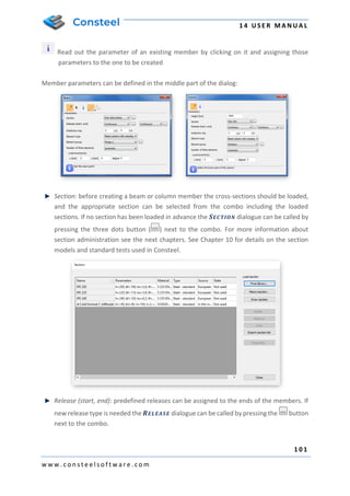
  • 1. 1 4 U S E R M A N U A L 1 0 1 w w w . c o n s t e e l s o f t w a r e . c o m Read out the parameter of an existing member by clicking on it and assigning those parameters to the one to be created Member parameters can be defined in the middle part of the dialog: Section: before creating a beam or column member the cross-sections should be loaded, and the appropriate section can be selected from the combo including the loaded sections. If no section has been loaded in advance the SECTION dialogue can be called by pressing the three dots button ( ) next to the combo. For more information about section administration see the next chapters. See Chapter 10 for details on the section models and standard tests used in Consteel. Release (start, end): predefined releases can be assigned to the ends of the members. If new release type is needed the RELEASE dialogue can be called by pressing the button next to the combo.
  • 2. 1 4 U S E R M A N U A L 1 0 2 w w w . c o n s t e e l s o f t w a r e . c o m Initial bow imp.: half-sine wave shaped initial crookedness can be defined in the two local direction perpendicular to the member reference axis (“y,z”) with the given amplitude at the mid-length. Element type: Section made from steel: Two choices are possible Beam-column with warping and Tension bar, these types influence the finite element type used in the analysis. The beam-column with warping is a special element with 14 degree of freedom, including the warping of the thin-walled cross section. It is an important effect in case of structures with standard, open steel profiles. The tension bar can only resist tensional axial force (no bending or torsional moments and shear) if it got compression the analysis neglects its effect. Reinforce concrete or Composite sections: There is only one choice, the General beam-column type this is the commonly used 12 degree of freedom finite element. Element group: the members can be sorted out into element groups for various purposes (selection, dominant results, sensitivity analysis etc.). if new element group is needed the GROUPS OF STRUCTURAL MEMBERS dialogue can be called by pressing the button next to the combo. Number of finite elements: the required number of finite elements used on the member in the analysis can be set. The default automatic option gives a sufficient result in the most cases. Local eccentricity: member eccentricity can be defined in the local coordinate system (“y, z”) of the member, and the section can be rotated about the local coordinate “x”. At the bottom of this dialog there is an instruction and command area for guiding the user. IT SHOULD BE NOTED THAT NOT ONLY THE ECCENTRIC AXIAL FORCE PRODUCES INFLUENCE IN THE ANALYSIS (ADDITIONAL BENDING MOMENTS) BUT THE ECCENTRIC BENDING AND TORSIONAL MOMENTS (ADDITIONAL BENDING AND TORSIONAL MOMENTS AND BIMOMENT)! 5.2.1. STEEL MEMBERS As the first step of line member modelling, cross sections must be loaded into the model. This can be performed either from the SECTION ADMINISTRATOR directly, either from the BEAM dialogue. In Consteel 13, in addition to the cross-sections in the standard section database and the macro section, it also allows you to load drawn (unique) sections.
  • 3. 1 4 U S E R M A N U A L 1 0 3 w w w . c o n s t e e l s o f t w a r e . c o m It is important to note that in Consteel, material quality is an attribute of the cross- section, therefore it must be defined when loading the cross-section! 5.2.1.1. CROSS SECTION LIBRARIES In CONSTEEL 13, the following standard cross section libraries are available: Standard (European) cross section library American section library (metric and imperial) British section library Chinese section library Russian section library Manufacturers 'profiles (catalogues of individual manufacturers' profiles) 5.2.1.2. MACRO SECTIONS In CONSTEEL 13, the following macro sections are available in 4 groups: 1) Sheet welded types Welded I or H section Welded box section Welded Maltese cross section Welded half Maltese cross section Welded hat section Welded T WQ section Slant flange welded I or H section C section 2) Hot rolled types
  • 4. 1 4 U S E R M A N U A L 1 0 4 w w w . c o n s t e e l s o f t w a r e . c o m Rolled I or H shape (with parallel flange) Rolled angle (parallel leg) Rolled channel (parallel flange) CHS shape T shape (half I) Plate Round bar RHS 3) Cold-formed types RHS CHS L profile unsymmetrical U section Z shape C shape Sigma section Zeta section Slope omega section In the case of cold-formed macros, it is also possible to provide stiffeners for the last 5 profile types. On the flanges once or twice bent edge stiffeners, and two different types of intermediate stiffeners can be defined. On the webs three different types of intermediate stiffeners can be defined. In the case of web stiffeners, it is also possible to double the stiffeners. The stiffeners defined this way are taken into account in the calculation of distortional buckling as defined in EN 1993-1-3.
  • 5. 1 4 U S E R M A N U A L 1 0 5 w w w . c o n s t e e l s o f t w a r e . c o m For cold formed macro sections, if they are made of coated material, the thickness tolerance category as defined in EN 10143 shall also be provided. There are two categories: normal and special. Accordingly, the design wall thickness of the cross section is calculated according to EN 1993-1-3 section 3.2.4. In general construction practice, such sections are most often made of coated steel sheets according to the aforementioned EN 10143 standard, and therefore these macros are based on the thickness tolerance categories defined in this standard. IMPORTANT, THAT IF THE DESIGNER DOES NOT CHOSE THE COATED MATERIAL FROM THE DATABASE AND THAT THE SELECTED MATERIAL HAS A THICKNESS TOLERANCE MORE THAN 5%, IN THIS CASE THE CALCULATION WILL NOT BE EXACT. TO AVOID THIS, YOU MUST IMPORT THE CROSS SECTION INTO THE SECTION DRAWER MODULE AND PROVIDE THE REAL THICKNESS TOLERANCE. (THE SECTION DRAWER SEE IN THE FOLLOWING CHAPTER!) 4) Compound types I or H shape reinforced by channel at one flange I or H shape reinforced by channels at both flanges I or H shape reinforced by half I or H I or H shape reinforced by half I or H shapes at web
  • 6. 1 4 U S E R M A N U A L 1 0 6 w w w . c o n s t e e l s o f t w a r e . c o m I or H shape reinforced by angels at flange I or H shape reinforced by plates at flanges I or H shape reinforced by I or H shape at flange Closed shape with angles and plates Closed 2U Closed 2I I plus U I from 2U Half Maltese Battened section 5.2.1.3. SECTION DRAWER In Consteel 13, the third option for creating a section is section drawing in the SECTION DRAFTER module. The function can be started by pressing the DRAW SECTION button in the SECTION ADMINISTRATION dialog box. As a first step, after the command has been executed, you will need to select a section type and material quality in a pop-up window and enter the section name. There are two types of cross-sections: Cold formed section General thin-walled section The type of cross section has a fundamental influence on its later operation. With a cold formed section, you can create sections with only one line, which have a uniform wall thickness, automatically create a curve between segments, and cannot be closed. In addition to the strength, local and global stability tests, the program also takes into account the effective cross-sectional reduction due to distortional buckling, in accordance with EN 1993- 1-3. In the case of general thin-walled sections, sheets of different thicknesses may be used, the section need not be drawn on a single line, and single-closed sections may also be made. This type is basically used to create sheet welded sections. For these sections, only strength, local and global stability tests can be performed. After selecting the segment type, clicking on the NEXT button opens a separate window for the SECTION DRAFTER MODULE, the contents of which are slightly different depending on the type of section you choose. The profile drawing window is structured as follows:
  • 7. 1 4 U S E R M A N U A L 1 0 7 w w w . c o n s t e e l s o f t w a r e . c o m 1# Drawing Area 2# Commands 3# Diagnostic Messages: Displays various warning and error messages 4# Navigation: Use the BACK and NEXT buttons to move between the different phases of the section drawing 5# User Interface Settings: There are four tabs on the pop-up window that provide parameters and switches for adjusting the VISIBILITY, GRID, SNAP, and OBJECT SIZES. 6# Specify Parameters: always displays parameter panels for the current function and the selected item. 5.2.1.3.1. DRAWING OF COLD FORMED SECTIONS Cold formed sections are defined in 4 phases. (1) Drawing of the geometry (2) Specify design parameters for strength and global stability tests (3) Specify design parameters for local buckling tests (4) Defining stiffeners (1) Drawing of the geometry The section geometry is edited in the first phase. Stiffeners can be easily and quickly drawn using macros. It is also possible to import a previously loaded cross section. 1 Q 2 3 4 5 6
  • 8. 1 4 U S E R M A N U A L 1 0 8 w w w . c o n s t e e l s o f t w a r e . c o m DRAW POLYLINE shortcut to start editing geometry. Drawing can also be done by selecting endpoints in the drawing space or by entering coordinates in the DRAW LINE pop- up window. Coordinates can be specified in Cartesian or Polar coordinates, local or global . In the case of local input, the coordinate system is rotated according to the grid angle, in the case of global input the coordinate system does not change. The positioning of the plate segments relative to the drawn reference line (offset) can be centered, left, or right aligned. You can change this during drawing or later, one by one, in the PLATE SEGMENT PARAMETERS panel on the sidebar. Roundings are created automatically when you draw plate segments. The radius of roundings can be modified subsequently, by selecting the curvature, individually in the sidebar, or uniformly over the entire section. You can also enter the nominal sheet thickness here. In the section drawing window, after typing each parameter, you must also press ENTER for the entered value to take effect! You can continue drawing plate segments only from one endpoint. When you have finished drawing, you can exit the command by pressing the ESC key or by clicking the EXIT button. If you want to edit the drawing, you can delete and redraw that section to fix the problem.
  • 9. 1 4 U S E R M A N U A L 1 0 9 w w w . c o n s t e e l s o f t w a r e . c o m The following two commands will launch the INTERMEDIATE STIFFENER and EDGE STIFFENER macros. There are three types of intermediate stiffeners and two types of edge stiffeners. A panel for specifying the geometry parameters of the stiffener appears in the right sidebar. You can also specify which side of the segment the stiffener have to be placed. After the command is executed, pointing to a plate segment with the cursor, the stiffener corresponding to the set parameters appears. After adjusting the parameters, you can place the stiffener by clicking on the desired location. After positioning, by selecting the stiffener, the parameters, and in case of intermediate stiffeners the positions remain adjustable. Note that these commands are just macros to make the drawing process easier. The plate segments drawn in this way, only after defining in Phase 4, actually become code compliant stiffeners. With the IMPORT SECTION command, you can import and further edit a previously created library, macro, or drawn section. Obviously, only a cold formed, one-line drawing can be imported. After the command has been issued, a window will pop up showing the sections that are suitable for importing. Pressing the NEXT button loads the selected section. If you have a previously drawn geometry, the program will warn you that current section you have drawn so far will be deleted. The section imported retains all its geometry and design parameters and remains editable. The EXPLODE SECTION command converts the drawn stiffeners and roundings into individual line and arc segments. After the exploding, also for these elements, only the thickness and offset can be changed, not their size and position. By exploding, elements previously defined as one segment, turn into separate segments whose classification can be defined independently. The PLACE DIMENSION command is used to apply dimension lines to each segment of the section. There are two icons in the pop-up window that allow you to choose how to place the dimension line: Dimension Placement in Cartesian Coordinate System. You can specify dimension lines in the Y or Z direction. Placement of dimension line parallel to the line segment. To place a dimension line, click on one of the line segments and click again to place the dimension line in the desired position. (2) Specify design parameters for strength and global stability tests
  • 10. 1 4 U S E R M A N U A L 1 1 0 w w w . c o n s t e e l s o f t w a r e . c o m After the geometry has been drawn, the standard parameters required for the strength and global stability analysis must be set. In the first drop-down menu, you must choose the manufacturing type of the cross section. It can be cold rolled, press broken or other cold formed. After that the thickness tolerance required to calculate the design wall thickness and the number of the 90° bends must be entered. The number of bends is automatically calculated when a macro profile is imported. In the case of a drawn section, this field must be completed by hand. Next, the flexural and torsional buckling curves must be selected. If the section is later used on a line member which is part of a PURLIN LINE object, the lowest curve selected in the Lateral-torsional buckling for purlin line field will be considered in the analysis. (3) Specify design parameters for local buckling tests Moving to the third phase, the drawing area displays the lengths of the segments used to calculate effective length (bp). By selecting a segment, you can specify on the sidebar whether, and in which direction, that segment should be considered in the calculation of the shear buckling. The following field specifies how the segment is to be considered in the classification. There are three options to choose from: Automatic classification and efficient length calculation (default) Ignore classification and consider total length Ignore classification and do not consider the plate in the effective cross section
  • 11. 1 4 U S E R M A N U A L 1 1 1 w w w . c o n s t e e l s o f t w a r e . c o m (4) Defining stiffeners For the drawn stiffeners to be standard compliant stiffeners in the calculation, they need to be defined at this phase. The first step is to decide whether the section is cold-formed Z or C like section or whether it is a general shape. You can choose by using the radio buttons in the sidebar. When choosing a Z or C like profile, the calculation takes into account the stress of the other flange as well as the stiffness of the web when supporting the flange. To do this, of course, you need to specify which parts of the section make up the lower and upper belts, and the web, and you must add its length. By choosing a general shape section, the edge stiffeners are calculated independently of each other. A further important difference is that only a line member created with a Z-C like section can later be used to in a PURLIN LINE, PURLIN SUPPORT ZONE, or PURLIN OVERLAP. (See Chapter 5.12.) A new panel appears next to the left-hand diagnostic panel, which shows the stiffeners in a tree structure. To specify the stiffeners, use the icons on the command line in the top left of the window: SELECT NON-STIFFENED FLANGE: Only applicable for Z or C like sections. If one of the flanges is unstiffened, this command defines this flange. You must select the line segments of the unstiffened flange, and then click on ENTER or press the ENTER key to finish entering. SELECT EDGE STIFFENER AND DOUBLE EDGE STIFFENER: Follow the instructions in the popup window to define the stiffener in 4 steps. The first step is to select the segment(s) that make up the stiffener by framing or clicking on it, and then click ENTER or press ENTER key to finish the entry. Then, select the flange which must be stiffened, and press ENTER again to complete the operation. The next step is to specify the segment that forms the web, and finally determine the length of the web by two points. Each step must be completed in the same way with ENTER. The process steps can be followed in the right panel where OK will be displayed on all three lines when correctly entered.
  • 12. 1 4 U S E R M A N U A L 1 1 2 w w w . c o n s t e e l s o f t w a r e . c o m If the section is set to Z or C, the position of the belt must also be entered in the drop-down menu at any step of the process. Click the arrow icon to re-enter a component. Finally, the critical stress of the stiffener must be specified in the lowest section of the panel. Here you can choose between automatic calculation or manual input. It is important that the automatic calculation only works with Z or C like sections, as the Eurocode gives solutions only for such cases. SELECT INTERMEDIATE STIFFENER AND DOUBLE INTERMEDIATE STIFFENER : Like the process of defining edge stiffener, you must select the segments that make up the stiffener and press ENTER to accept the entry. No further steps are required; however, the critical stress of the stiffener must be specified. The stiffeners can be selected after input and their parameters can be changed or they are able to be deleted by pressing the DEL key. Finally, you can close the section drawing by pressing the SAVE EXIT button on the phase indicator panel. 5.2.1.3.2. GENERAL THIN-WALLED SECTIONS General thin-wall sections are defined in 3 phases. (1) Drawing of the geometry (2) Specify design parameters for strength and global stability tests (3) Specify design parameters for local buckling tests (1) Drawing of the geometry Fewer commands are available for editing by this type of sections since it is not possible to draw and define stiffeners. The editing process is similar to the previous one. The dialog used for the DRAW LINE command is the same as the dialog for the cold- formed section, see the previous subchapter for details.
  • 13. 1 4 U S E R M A N U A L 1 1 3 w w w . c o n s t e e l s o f t w a r e . c o m Due to the nature of the section, the drawing differs from the previous one since each segment can be given different thicknesses and a closed segment can also be created. When drawing from an endpoint and clicking on an intermediate point of an already drawn segment will cause the line drawing to "skip" to that point and continue editing from that point. The so-called "Dummy" segments required for section modelling are also created, which appear on the screen as a brown dashed curved line. MOVE POINT AND EDGE can be used to move an end point or an entire segment. If you select a point, the next step is to enter the endpoint of the move immediately, if selecting an edge, first click on the start point and then the end point of the move. The IMPORT SECTION command works exactly as described in the previous part. See there for details. The PLACE DIMENSION command works exactly as described in the previous part. See there for details. (2) Specify design parameters for strength and global stability tests After the geometry has been done, the standard parameters required for the strength and global stability boundaries must be provided. Compared to the previous subchapter, it is not possible to specify a thickness tolerance here, nor is it possible to define a purlin line buckling curve, since these sections cannot be used for a purlin line object. (3) Specify design parameters for local buckling tests By moving to the third and final phase, the classification of the segments must be made in the same way as described in the previous section. See details in the previous chapter. You can finish editing with the SAVE EXIT button.
  • 14. 1 4 U S E R M A N U A L 1 1 4 w w w . c o n s t e e l s o f t w a r e . c o m 5.2.2. REINFORCED CONCRETE MEMBERS Definition of reinforced macro sections can be performed from the MACRO DIALOGUE. There are two main types of reinforced concrete sections. SECTIONS WITH DESIGN OPTION (#1) and SECTIONS WITHOUT DESIGN OPTION (#2). 5.2.2.1 REINFORCED CONCRETE CROSS SECTIONS WITH DESIGN OPTION REINFORCED CONCRETE CROSS SECTIONS WITH DESIGN OPTION, are represented with a gray cross section pictogram on the MACRO SECTION dialogue. In Consteel 13, there are two section types with design option: Solid circle section Rectangular section After choosing one of the available cross sections, on the section dialogue, only the overall dimensions, the concrete material grade and the modulus of elasticity applied in the structural analysis must be set. Because the reinforcement distribution may vary along the span of the concrete member, definition of the reinforcement settings must be made through a dedicated REBAR EDITOR ( ) function, which can be found on the STRUCTURAL MEMBERS TAB. 1 2
  • 15. 1 4 U S E R M A N U A L 1 1 5 w w w . c o n s t e e l s o f t w a r e . c o m 5.2.2.1.1 BEAM REINFORCEMENT DEFINITION Creation of beam reinforcement objects can be created if the Beam rebars option is selected on the left panel of the REBAR EDITOR dialogue. The REBAR EDITOR ( ) dialogue can be found on the STRUCTURAL MEMBERS TAB #2 - If there are reinforced concrete cross sections with design option are loaded into the model, new beam reinforcement objects can be created by pressing the ADD button. Switching between different reinforcement objects works by selecting one from the dropdown menu. If a reinforcement object is copied, the copied object will inherit the parameters of the original object. The DELETE button will delete the actively selected reinforcement object only. #3 – On the middle part of the dialogue, the cross section can be selected, for which the reinforcement settings are desired to be set on the other parts of the dialogue. The overall dimensions, and the material grade will be written below the dropdown menu of the selected cross section. #4 – The bottom part of the dialogue, is a multifunctional panel. Here, the longitudinal and transverse directional rebars can be defined, envelope diagrams for bending and shear is defined, predesign values like (Mrd and Vrd) is shown and detailing rules are checked. Main functions of the panel in details: 1 2 3 4
  • 16. 1 4 U S E R M A N U A L 1 1 6 w w w . c o n s t e e l s o f t w a r e . c o m o Graphical display: After a reinforcement object is placed on a concrete member using the PLACE button, the length of the member on which the object is applied is highlighted. If there are available analysis results for the member, the bending moment and shear diagrams are shown on the panel, both for individual load combinations with the dropdown menus, and as envelope diagrams. Switching between the bending and shear diagrams can be performed with the upper left dropdown menu. Med and Ved values are also shown Mrd, Vrd Vrd,c and Vrd,max values are also represented on the panel, if there are applied longitudinal and shear reinforcements (more on that below). Unfilled detailing rules are also highlighted as warnings at the bottom of the panel. o Adding longitudinal rebars: If the LONGITUDINAL REINFORCEMENT option is selected in the upper left dropdown menu, using the button it is possible to add rebars to the member. On the ADD BEAM REBAR dialogue, position, quantity, and diameter settings must be given. After pressing the ADD button, the graphical representation of the rebars will appear on the graphical display Deletion of a rebar can be performed by pressing the button and choosing the rebar with the sign. o Adding stirrups: If the TRANSVERSE REINFORCEMENT option is selected in the upper left dropdown menu, using the button it is possible to add stirrups to the member. On the ADD BEAM REBAR dialogue, only the spacing and the start-end position must be defined. Diameter of the stirrups must be given on the main rebar editor dialogue. After pressing the ADD button, the graphical representation of the rebars will appear on the graphical display Deletion of a rebar can be performed by pressing the button and choosing the rebar with the sign.
  • 17. 1 4 U S E R M A N U A L 1 1 7 w w w . c o n s t e e l s o f t w a r e . c o m A reinforcement object can be placed on more members if the members has the same parameters (length and cross section) using the PLACE button. If a reinforcement object is placed on more members with different lengths, a copy of the original reinforcement object will automatically be created for each member with a different length. 5.2.2.1.2 COLUMN REINFORCEMENT DEFINITION By choosing the COLUMN REBAR option (#1) on the left side panel of the REBAR EDITOR dialogue, column reinforcement related data will be available on the dialogue. #2 – If there are loaded cross sections in the model with design option, new reinforcement object can be created using the ADD button. A reinforcement object is created by default, but any number of objects can be created. Switching between them 1 2 4 5 3 6
  • 18. 1 4 U S E R M A N U A L 1 1 8 w w w . c o n s t e e l s o f t w a r e . c o m is possible using the dropdown menu, DELETION and COPY can be performed using the dedicated buttons. #3 – In the dropdown menu the available reinforced concrete cross sections will be listed, which has design option. Overall dimensions and material grade are listed below the chosen cross section, while the graphical representation of the section is shown at the middle panel (#5). #4 – At the left side of the dialogue, parameters of the main reinforcement (concrete cover, diameter, material grade), and parameters of the stirrups can be adjusted (diameter, spacing) #5 – At the middle part of the dialogue, the cross section which is selected at the right panel (#3) is shown, with the dynamic representation of the reinforcements. On this panel, additional reinforcements can be added both for y and z directions, by checking the checkboxes at the bottom part, and defining the parameters for spacings, and diameters and quantity. #6 – In order to be able to run the design process (discussed in detail at CHAPTER 9.4 REINFORCE CONCRETE DESIGN) for the column, additional design parameters must be set for the column. By clicking the (…) button, the design parameters will be opened, where all the necessary parameters are listed, and can be set individually. Design parameters are separate objects, what means that more sets of parameters can be created, saved, and used for the reinforcement object. The required parameters are buckling, curvature calculation and shear check parameters: 5.2.2.2. REINFORCED CONCRETE CROSS SECTIONS WITHOUT DESIGN OPTION Members in the model, which are defined with REINFORCED CONCRETE CROSS SECTIONS WITHOUT DESIGN OPTION are not allowed to use in the standard checks at the global checks
  • 19. 1 4 U S E R M A N U A L 1 1 9 w w w . c o n s t e e l s o f t w a r e . c o m tab. Members with these types of cross sections can provide analysis results (see CHAPTER 8.6), and the resistance surface (see CHAPTER 10.4.5.2), which of course takes into account the effect of the applied reinforcements of the cross section on the side of stiffness. Available cross sections are: Solid circle section Ring shaped section Double symmetric I section Singly symmetric I section I section with tapered flange width Rectangular section Rectangular section with hole Rectangular section with tab T shaped section T shaped section with tapered flange width Trapezoid section Converse T shaped section When defining the sections, overall dimensions, concrete material grade, reinforcement parameters and the applied stiffness during the analysis must be set. 5.2.3. COMPOSITE COLUMNS The first step is to define a composite column cross-section. Five types of cross-section are available: fully encased I section in concrete, partially encased I section in concrete, encased Maltese cross-section in concrete, fully encased I section in hollow section and fully encased I
  • 20. 1 4 U S E R M A N U A L 1 2 0 w w w . c o n s t e e l s o f t w a r e . c o m section in circular hollow section. The cross-section macros can be found among the MACRO SECTIONS. During the creation of the cross-section the parameters of the concrete section, reinforcement and the encased steel section must be set. For the structural analysis two types of elastic modulus can be used which can be selected on the middle part of the cross-section creation dialog. Standard initial sways also can be defined in y and z directions for the cross-section. If the initial sways are applied than the cross-section check is enough according to the EuroCode. Stability check is not necessary.
  • 21. 1 4 U S E R M A N U A L 1 2 1 w w w . c o n s t e e l s o f t w a r e . c o m 5.2.4 COMPOSITE BEAMS The first step is to define a composite beam cross-section. There are two types available: composite beam with solid concrete slab and composite beam with profiled steel sheeting. The cross-section macros can be found among the MACRO SECTIONS. When creating a new composite cross-section, the effective breadth must be defined. It is important to know that during the analysis the actual effective breadth is automatically calculated based on the design parameters. The effective breadth which must be set at the cross-section creation is used in the graphics and for determining the self-weight of the beam. It is also possible to create an edge composite beam with different width in left and right side. Rebars can be easily defined either with pitch or with area (mm2/m). After the composite cross-section is defined it can be used for member creation the same way as a steel cross-section.
  • 22. 1 4 U S E R M A N U A L 1 2 2 w w w . c o n s t e e l s o f t w a r e . c o m Before running the analysis select the composite beam(s) and set the DESIGN PARAMETERS on the OBJECT PROPERTIES. In the DESIGN SETTINGS WINDOW, you can set the distance between parallel beams, the number of shear studs, the type of analysis, moment redistribution and the support point positions along the member. The support position table can be automatically filled up by clicking on the button above the table. You can create more design parameters and assign them to different members. You can also use more design parameters to easily switch between them to find the best parameters or to simply compare different settings.
  • 23. 1 4 U S E R M A N U A L 1 2 3 w w w . c o n s t e e l s o f t w a r e . c o m 5.2.5 HAUNCHED MEMBERS The created members can be strengthened, if necessary, by using the HAUNCH function ( ). The haunch can only be used for members with I type (IPE, HEA, welded I) sections, and the shape of the haunch is considered as half of a welded or hot-rolled I section (with one flange) with decreasing web height. In case of welded haunch, on the dialogue panel the length (L), start height (hs), end height (he) web thickness (tw), flange width (b), flange thickness (tf) and the characteristics of the haunch should be set. In case of hot rolled haunch, on the dialogue panel the Length (L), start height (hs), end height (he) ,the section (roll radius) and the characteristics of the haunch should be set. With a click on the ( ) button, sections can be loaded from the section administrator. With the black arrow button ( ) the geometrical parameters of the haunches can be loaded from the selected beam. The position of the haunch is set by simply clicking on the member the start point (where the height of the haunch is full) and the direction point of the haunch on the member. It should be noted that if the start point is a common end point of more members (this is the usual case, for instance at a beam-to-column connection point) then this point should be approached and clicked on the member to be haunched. The characteristics of the haunch denote the appropriate side of the haunch on the member according to the direction of its local “z” axis. In the case of usual beam position, it results the followings:
  • 24. 1 4 U S E R M A N U A L 1 2 4 w w w . c o n s t e e l s o f t w a r e . c o m lower upper symmetric THE HAUNCHES CAN BE SELECTED AND MODIFIED IN THE PARAMETER TABLE AS SEPARATE OBJECTS.
  • 25. 1 4 U S E R M A N U A L 1 2 5 w w w . c o n s t e e l s o f t w a r e . c o m IMPORTANT TO KNOW THAT FOR THE HAUNCHED PART OF THE MEMBER NEW SECTIONS ARE CREATED DURING THE AUTOMATIC FINITE ELEMENT GENERATION WHICH CONSIST OF THE ORIGINAL SECTION AND THE HAUNCH WITH APPROPRIATE WEB HEIGHT. THESE NEW SECTIONS ARE PLACED ECCENTRICALLY ON THE REFERENCE LINE OF THE MEMBER (EXCEPT THE SYMMETRICAL HAUNCH TYPE). THIS ECCENTRICITY CAUSES ADDITIONAL EFFECTS IN THE ANALYSIS RESULTS DUE TO THE ECCENTRIC POSITION OF THE SECTIONAL FORCES (FOR INSTANCE AT THE BEAM-TO-COLUMN CONNECTION POINT OF A FRAME WITH HAUNCHED BEAMS AND/OR COLUMNS THE EQUILIBRIUM OF THE IN-PLANE BENDING MOMENTS EXISTS ONLY IF THE ADDITIONAL MOMENTS FROM THE ECCENTRIC AXIAL FORCES ARE TAKEN INTO ACCOUNT) 5.2.6 TAPERED MEMBERS Tapered members are frequently used in the economic design of steel framed structures, so the fast and simple modelling of tapered members is of high importance. For the definition of a tapered member first a line member with welded I or H, box, or cold formed C section should be created in the model. Hot rolled and other shape of Macro section can’t be tapered.
  • 26. 1 4 U S E R M A N U A L 1 2 6 w w w . c o n s t e e l s o f t w a r e . c o m With the TAPERED MEMBER function ( ) the section height of these sections can be set to linearly varying along the member length. First the user must specify the parameters and beam eccentricity options for the member to be tapered on the TAPERED MEMBER dialogue. Specify the start (H1) and end section height (H2) independently of the original section height of the cross-section. The start value for section height applied at the start point of the member, the end value applied at the other end. To change the H1 and H2 values click the icon. The values will be changed, and selecting again the member for tapering, the sizes of the tapering will change adequately. The rules for the beam eccentricity of the tapered member relates to the axis of the originally positioned member to be tapered. 1. Place the centroid of the smaller section to the axis of the beam: the center of smaller H value of the tapered member will be positioned to the axis of the original beam 2. Place the centroid of the bigger section to the axis of the beam: the center of bigger H value of the tapered member will be positioned to the axis of the original beam 3. Place the centroid of the original section to the axis of the beam: the edge of the tapered member is coincident with the original member end and the tapering will start from this position.
  • 27. 1 4 U S E R M A N U A L 1 2 7 w w w . c o n s t e e l s o f t w a r e . c o m The relative position of the tapering can be –z (the left side of the tapered member will be parallel to the axis of the originally placed member), symmetric or +z (the right side of the tapered member will be parallel to the axis of the originally placed member). These definitions regulate the directions of the offset of the given height values along the local “z” axis of the tapered beam. Below shown the effect of the different relative positioning by the chosen eccentricity: 1. Place the centroid of the smaller section to the axis of the beam: the center of smaller H value of the tapered member will be positioned to the axis of the original beam -z symmetric +z 2. Place the centroid of the bigger section to the axis of the beam: the center of bigger H value of the tapered member will be positioned to the axis of the original beam -z symmetric +z 3. Place the centroid of the original section to the axis of the beam: The edge of the tapered member is coincident with the original member end the tapering starts from this position -z symmetric +z
  • 28. 1 4 U S E R M A N U A L 1 2 8 w w w . c o n s t e e l s o f t w a r e . c o m Activating the icon, by clicking an earlier created tapered member in the model, the values, the eccentricity, and the relative positioning will be read out of that clicked and appear in the dialog box. By clicking another member for taper, these parameters will be applied. IN CASE OF SELECTING A TAPERED MEMBER NOT ONLY THE MEMBER BUT THE TAPERING WILL BE SELECTED AUTOMATICALLY AND CAN BE MODIFIED IN THE PARAMETER TABLE AS SEPARATE OBJECT. IMPORTANT TO KNOW THAT FOR THE TAPERED MEMBERS NEW SECTIONS ARE CREATED DURING THE AUTOMATIC FINITE ELEMENT GENERATION WITH APPROPRIATE SECTION HEIGHTS. THESE NEW SECTIONS ARE PLACED ECCENTRICALLY ON THE REFERENCE LINE OF THE MEMBER (EXCEPT THE SYMMETRICAL TAPERING). THIS ECCENTRICITY CAUSES ADDITIONAL EFFECTS IN THE ANALYSIS RESULTS DUE TO THE ECCENTRIC POSITION OF THE SECTIONAL FORCES (FOR INSTANCE AT THE BEAM-TO-COLUMN CONNECTION POINT OF A FRAME WITH TAPERED BEAMS AND/OR COLUMNS THE EQUILIBRIUM OF THE IN-PLANE BENDING MOMENTS EXISTS ONLY IF THE ADDITIONAL MOMENTS FROM THE ECCENTRIC AXIAL FORCES ARE TAKEN INTO ACCOUNT)
  • 29. 1 4 U S E R M A N U A L 1 2 9 w w w . c o n s t e e l s o f t w a r e . c o m 5.3 SURFACE MEMBERS Plane surface members with uniform thickness can be modelled. Two options are available for surface member modelling: the arbitrary shaped and positioned plate member ( ); and the vertical and square wall member ( ). The latter one is a modelling aid for the frequently used definition of walls since only the reference base line and the two height values should be defined. In the PLATE and WALL definition panels the drawing functions are collected to create the plate with the desired shape. Arbitrarily shaped holes can be defined in existing plate members. Three parameters can be set: the thickness, the material, and the finite element size of the surface member. The finite element size is an approximate target maximum size for the finite element mesh used for the calculation of surface members.
  • 30. 1 4 U S E R M A N U A L 1 3 0 w w w . c o n s t e e l s o f t w a r e . c o m 5.3.1 PLATE REINFORCEMENT In case of concrete PLATES, reinforcements can be added to the model at the reinforcement dropdown menu, or by clicking on the (…) button. Diameters, covering and material can be set on the REINFORCEMENT dialogue: 5.4 DIAPHRAGM In-plane rigid element can be defined on the model in arbitrary planar. The added members’ distance from each other will be same in the plane of the diaphragm element. With diaphragm element the in-plane rigid structural elements for example slab, trapezoid sheet can be modelled. After clicking on the DIAPHRAGM ( ) icon on the STRUCTURAL MEMBERS tab a dialog window appears.
  • 31. 1 4 U S E R M A N U A L 1 3 1 w w w . c o n s t e e l s o f t w a r e . c o m Just like in the two-dimensional figure drawing there are different possibilities to draw the surface: draw a rectangle ( ), draw leaning rectangle ( ), draw circle ( ), draw polygon ( ). With the select function ( ) previously created LOAD TRANSFER SURFACE can be select to use as a diaphragm also. After drawing the surface, it is possible to select the members which are added to the diaphragm or all the planer members can add. DIAPHRAGM element can be used also as a LOAD TRANSFER SURFACE and surface loads can be placed on it. 5.5 RIGID BODY Arbitrary rigid body line can be defined on the model. Separate structural members can be linked with the rigid body. Before clicking on the RIGID BODY ( ) icon on the STRUCTURAL MEMBERS tab, the lines, members, and surface edges must be selected which should be converted to rigid body. By clicking on the APPLY button, the rigid body is created. 5.5.1 MODIFYING RIGID BODY RIGID BODY can be modified by selecting it and changing the lines, members, and surface edges selection on the property bar. With the black arrow, previously selected members can be removed from the selection or new members can be added. 5.6 CONVERT MEMBERS TO PLATES The selected members can be automatically converted to plates with CONVERT MEMBERS TO PLATES function ( ).
  • 32. 1 4 U S E R M A N U A L 1 3 2 w w w . c o n s t e e l s o f t w a r e . c o m The following members with section can be converted to plates: Hot-rolled I, H, and tube section Cold formed C, Z, and tube section Welded I, H, and box section By clicking on the APPLY button the selected members will be converted to plates. During the conversion the given eccentricities are considered therefore the eccentric loads and supports will be in the same position after the conversion. Attaching nodes of the connecting members, haunches and tapered members are automatically converted. In case of hot-rolled sections not only the flanges and web are converted to plates but also the neck area with a suitable additional plate element. Therefore, the section properties of the original member and the converted are the same. 5.7 FRAME CORNER WIZARD The FRAME CORNER WIZARD is an optional function for modelling and calculation of the corner regions of structural models more realistically considering the overlapping of connected members. The function automatically identifies the corner zones and applies special treatment for the geometrical modelling, buckling analysis, plastic analysis, and global checks. The main mechanical background is that these – generally stiffened – corner zones have usually significantly different behavior than the connected beam members. Since these zones
  • 33. 1 4 U S E R M A N U A L 1 3 3 w w w . c o n s t e e l s o f t w a r e . c o m are very short the behavior is influenced dominantly by the shear effect while the connected members have beam-column behavior with dominant bending effect. Functions of the frame corner wizard dialogue: #1 - With the button frame corner recognition can be turned on, and off.: By turning on frame corner recognition, frame corner definition can be started. Already defined frame corners can be turned off by clicking the button and turned on again if it is desired. #2 - With the more about the function button, a new panel will open, where detailed information about the function is available. #3 - Displays the model portion tree, in which it can be decided that what type of frame corner should be applied on which portion. It is important to note, that special frame corners (#5, #6, #7) can only be placed on model portions. The default frame corner type can be applied on the whole model. To place a special frame corner, it is necessary to select a model portion, and then with a click on a type of frame corner and on the apply button, the frame corner will be placed on the model. #4 - Default frame corner: 7. DOF displacements of end nodes of neighboring elements are transferred independently of the topology of the joint 1 2 3 4 5 6 7
  • 34. 1 4 U S E R M A N U A L 1 3 4 w w w . c o n s t e e l s o f t w a r e . c o m #5 - Box-type stiffened bolted or welded joint: Placement of a constraint element between neighboring elements, resulting displacements with opposite sign of 7. DOF of their nodes located at the boundary of the corner zones. #6 - Bolted or welded joint with diagonal endplate: Placement of a constraint element between neighboring elements, resulting equal displacements of 7. DOF of their nodes located at the boundary of the corner zones. #7 - Box-type stiffened bolted or welded joint with additional 1 or 2 diagonal stiffener(s): Placement of a constraint element between neighboring elements, resulting no displacements of 7. DOF of their nodes located at the boundary of the corner zones. After clicking on the APPLY button the program detects the overlapping zones of the members in the identified connection nodes including occurrent eccentricities, haunches, or tapered members. The member segments inside the overlapping zones are separated and handled specifically: ▪ Geometry: the haunch is started at the end of the truncated member (at the end of the overlapping member segment). In this way the real dimensions and position of the haunch is modelled
  • 35. 1 4 U S E R M A N U A L 1 3 5 w w w . c o n s t e e l s o f t w a r e . c o m ▪ Buckling analysis: the finite elements belonging to the beam segments inside the overlapping nodes are left out from the buckling analysis (as it would be an unselected model portion). The reason is that in this zone member buckling cannot occur, and the effective buckling lengths of the members start outside of this zone ▪ Plastic analysis: the plastic hinges cannot be formed inside the corner zone. Accordingly, the plastic hinges are formed at the theoretically exact positions (for instance on the column below the haunch) and not in the connection node where the “virtual” bending moment is the highest ▪ Global checks: the global checks (including section and stability checks) are performed only for the member parts outside of the corner zone. In this way the “virtual” peaks of the bending moments at the connection nodes inside the corner zones (which has no real mechanical meaning) are left out from the design checks and members are checked for the real, considerably bending moment (and the corresponding other internal force) values.
  • 36. 1 4 U S E R M A N U A L 1 3 6 w w w . c o n s t e e l s o f t w a r e . c o m ▪ Connection design: similarly to the earlier point the design bending moment and shear force values for the connection design are taken from the end of the truncated members where a beam-to-column connection is applied to the connection node where corner zone is defined 5.8 MATERIALS New material grades can be defined as one of the three different types of material: steel, concrete, and concrete reinforcement. The latter is only used for the rebar reinforcement of concrete or composite cross sections. The material parameters are taken from the appropriate Structural Eurocode chapters (EN 1993-1-1 for steel and EN 1992-1-1 for concrete and reinforcement), and the default – indelible – material types are set with the standard values. New materials can also be created with arbitrary parameters.
  • 37. 1 4 U S E R M A N U A L 1 3 7 w w w . c o n s t e e l s o f t w a r e . c o m In Consteel only elastic material is considered in the analysis, so the calculation results are only affected by the elastic modulus, Poisson factor, density (if the self-weight of the structure is considered) and temperature expansion factor (if temperature load or fire is applied). In case of concrete material, the Effective elastic modulus is used in the analysis as it defined in the EC 2. IMPORTANT TO NOTE THAT IN CASE OF BAR MEMBERS (BEAMS, COLUMNS) THE MATERIAL IS THE PARAMETER OF THE CROSS SECTION OF THE MEMBER, SO THE CURRENT MODIFICATION SHOULD BE APPLIED FOR THE APPROPRIATE CROSS SECTION. THIS FEATURE ALLOWS THE DEFINITION OF CROSS SECTIONS WITH MULTIPLE MATERIALS (E.G. COMPOSITE SECTION). ACCORDINGLY, IF
  • 38. 1 4 U S E R M A N U A L 1 3 8 w w w . c o n s t e e l s o f t w a r e . c o m IDENTICAL CROSS SECTIONS WITH DIFFERENT MATERIAL ARE LIKED TO BE USED IN ONE MODEL THEN MULTIPLE CROSS SECTION DEFINITION IS NEEDED! 5.9 SUPPORTS There are three types of supports in Consteel: point support, line support, and surface support. Supports can be placed according to the Point loads can be placed according to the Global ( ), Local ( ) or the User coordinate system ( ). Placing supports according to the member local coordinate system is very useful feature when working with sloping members. The visibility of the local coordinate system can be turned on with the Visibility of the coordinate systems option and the name of the axes can be shown on the screen using the appropriate options of the Visibility of labels functions.
  • 39. 1 4 U S E R M A N U A L 1 3 9 w w w . c o n s t e e l s o f t w a r e . c o m 5.9.1 POINT SUPPORT ( ) Point supports can be placed on any part of a line member or surface member (predefined points are not needed; end points or snap points can be used). With the black arrow button ( ) MULTIPLE PLACING is possible with window selection. With the MULTIPLE SUPPORT placement function ( ), more supports can be placed along a bar member at once by defining the relative distances between the support points. Support placement starts from the start point (End A) of the member. If there is an applied frame corner on the member, the first distance will be measured from the edge of the corner zone. Supports placed with multiple support function will act like one object. Relative distances can be edited later at any time at the object properties by selecting the multiple support.
  • 40. 1 4 U S E R M A N U A L 1 4 0 w w w . c o n s t e e l s o f t w a r e . c o m After selecting the coordinate system, the type of the support must be selected from the list- box. There are several point support types predefined. By positioning, the used coordinate system determines the orientation of constrains of the support. Using the Global ( ), Local ( ) or the User coordinate system ( ) the orientations of the constrains represented by the support will be different: By changing the eccentricity of the supported object, the support will keep the orientation to the coordinate system which was used by placing the support. If any special supports are needed during the modelling process different from the predefined support types, then click on the support definition button ( ). With the NEW button new type of point support can be defined. 7 DOFs (Degrees of Freedom) can be set to free, fix or semi-rigid. For semi-rigid DOF the stiffness must also be set in kN/mm, or kNmm/rad.
  • 41. 1 4 U S E R M A N U A L 1 4 1 w w w . c o n s t e e l s o f t w a r e . c o m The support type names can be clearly understood. For instance, “x,y,z, xx” means any movement is fixed in x, y and z direction and the rotation around x axe is also fixed. All the rest DOFs are free. Local eccentricity can also be defined to the supports: (This feature can be used for example for modelling the support effect of the bracing which is not connected to the reference line of the member but supporting the flange of the beam.) The eccentricity of the support can be defined relative to the reference line of a section, or relative to the section geometry. The “0 - Reference line” local eccentricity type can be selected only from this list-box. Support eccentricity relative to the section geometry can be specified in two ways. The first way is: select one of the typical point of the section geometry (1-9) from the list, the second way is select one of the typical point (1-9) of the section relative position of the support by clicking the position on the graphical imitation of a section (click the button left to the list):
  • 42. 1 4 U S E R M A N U A L 1 4 2 w w w . c o n s t e e l s o f t w a r e . c o m Giving value for the y or z parameters for local eccentricity these values will be added to the above selected position. Changing the eccentricity of the supported object the new position of the support will be calculated accordingly. Depending on the type of the selected local eccentricity used by placing the support the transformation rules are the following: By selecting the “0 – Reference line” eccentricity type: Placing a support with this eccentricity type, for example changing the “y” eccentricity of the supported object, the support will keep its position relative to the reference line, not to the section. By changing the “Rotation angle” attribute of the supported object, the reference line also rotates, and the position of the support will rotate too.
  • 43. 1 4 U S E R M A N U A L 1 4 3 w w w . c o n s t e e l s o f t w a r e . c o m By selecting the 1 -9 eccentricity type: Placing a support with any of these eccentricity types, for example changing the “y” eccentricity of the supported object, the support will keep its position relative to the section. By changing the “Rotation angle” attribute of the supported object, the position of the support will rotate too. Example for the different types of eccentricity: 1. Example: Both supports were placed with -150mm eccentricity in the y direction, but left case was defined relative to the reference line of a section and the right case was defined relative to the middle-middle point of the section geometry. If the eccentricity of the columns is changed to y= 100mm, the new position of the supports is as follows:
  • 44. 1 4 U S E R M A N U A L 1 4 4 w w w . c o n s t e e l s o f t w a r e . c o m In case of the left case the position of the support did not change, because the position of the reference line of the column also did not change, but in case of the right case the support was moved with the points of the section of the column. 2. Example: The support is placed according to the global coordinate system; the eccentricity is 300 mm in the z direction of the local coordinate system of the supported column from the reference line. If the column is moved with 300mm in the y direction in the local coordinate system, then the position of the support will not change.
  • 45. 1 4 U S E R M A N U A L 1 4 5 w w w . c o n s t e e l s o f t w a r e . c o m The support keeps its original relative position to the centerline of the column. If the column is rotated with 45 degrees, the support is also rotated accordingly, but it keeps the directions of its local axis parallel to the axis of the global coordinate system, which was selected by for positioning the support. 3. Example: The support is placed according to the global coordinate system, the eccentricity is 300mm in the z direction of the local coordinate system of the supported column relative to the middle-middle point of the section geometry.
  • 46. 1 4 U S E R M A N U A L 1 4 6 w w w . c o n s t e e l s o f t w a r e . c o m If the column is moved with 300mm in the y direction in the local coordinate system, then the support moves with the column. If the column is rotated with 45 degree, then the support moves together with the column.
  • 47. 1 4 U S E R M A N U A L 1 4 7 w w w . c o n s t e e l s o f t w a r e . c o m Selecting any of the above eccentricity types for positioning a support, changing the eccentricity of the supported object, the support will keep the originally given relative position from the new position of the supported object, and will keep the orientation defined by the applied coordinate system for placing this support. WARNING! BE AWARE THAT SINCE THE FINITE ELEMENT FOR THE STEEL BEAMS AND COLUMNS HAS 7 DOFS THE POINT SUPPORT ALSO HAS 7 DOFS, THE 7TH DOF REPRESENTS THE WARPING OF THE CROSS SECTION. ACCORDINGLY, IF A CROSS SECTION ON A CERTAIN PLACE IS CONSIDERED TO FIXED FOR WARPING (FOR INSTANCE IN HEAVILY STIFFENED JOINTS) THE 7TH DOF SHOULD BE FIXED.IN JOINTS CONSISTING SEVERAL MEMBERS (ESPECIALLY WHEN MEMBER ECCENTRICITIES ARE PRESENT) IT IS RECOMMENDED TO APPLY WARPING SUPPORT! 5.9.2 LINE SUPPORT ( ) Line supports can be assigned to existing lines (line members or edge of surface members) or to lines drawn for the support only (for instance on a surface).
  • 48. 1 4 U S E R M A N U A L 1 4 8 w w w . c o n s t e e l s o f t w a r e . c o m There are two default types for line supports the Fixed and the Pinned. With the button it is also possible to define a new line support by giving the attributes of constrains as it is needed. By positioning a line support the effect of the applied coordinate system and local eccentricity type are the same as for the point support. The select function ( ): The line support will be placed to the selected edge of a surface (an edge of boundary or an edge of a hole), or to an axis of a beam. The draw function: The line support will be placed between the first and the second point defined by the draw function on the surface or on an axis of a beam.
  • 49. 1 4 U S E R M A N U A L 1 4 9 w w w . c o n s t e e l s o f t w a r e . c o m 5.9.3 SURFACE SUPPORT ( ) Surface supports can be assigned to existing surfaces. There are no predefined supports for supporting surfaces. By pressing the button, the user can create new surface support types for specifying 3 constrains. By clicking on a plate object, all the surface of this selected object will be supported by the support. 5.10 LINK ELEMENTS Link element ( ) can be used to connect elements which are not directly connected to each other. Parameters of the link element can be defined in the middle part of the dialog: Position of connection: this parameter defines the place where the continuity acts in the percentage of the length of the link element. Value can be between 0 and 1 Rotation: rotation value defines the angle of the link element in degrees
  • 50. 1 4 U S E R M A N U A L 1 5 0 w w w . c o n s t e e l s o f t w a r e . c o m Release: predefined releases can be assigned to the specified position. If new release type is needed the RELEASE dialogue can be called by pressing the button next to the combo There are two different types of link element. 5.10.1 CONNECT TWO STRUCTURAL POINTS ( ) This type of link element can be used to connect two structural points. For example, if there is a cantilever on a relatively high tapered column (see image below) it is advisable to connect it not directly to the reference line of the column but with the link element. If it is connected the way like that, the analysis and design results will be more accurate, and the modelling will be more exact. 5.10.2 CONNECT TWO STRUCTURAL EDGES THAT ARE EQUAL LENGTH AND PARALLEL ( ) Equal length and parallel edges and members can be connected with this kind of link element. This type of link element can be used for example when connecting a slab eccentrically to a beam.