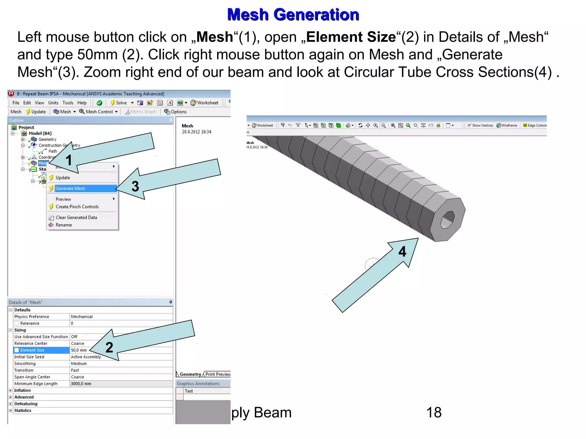
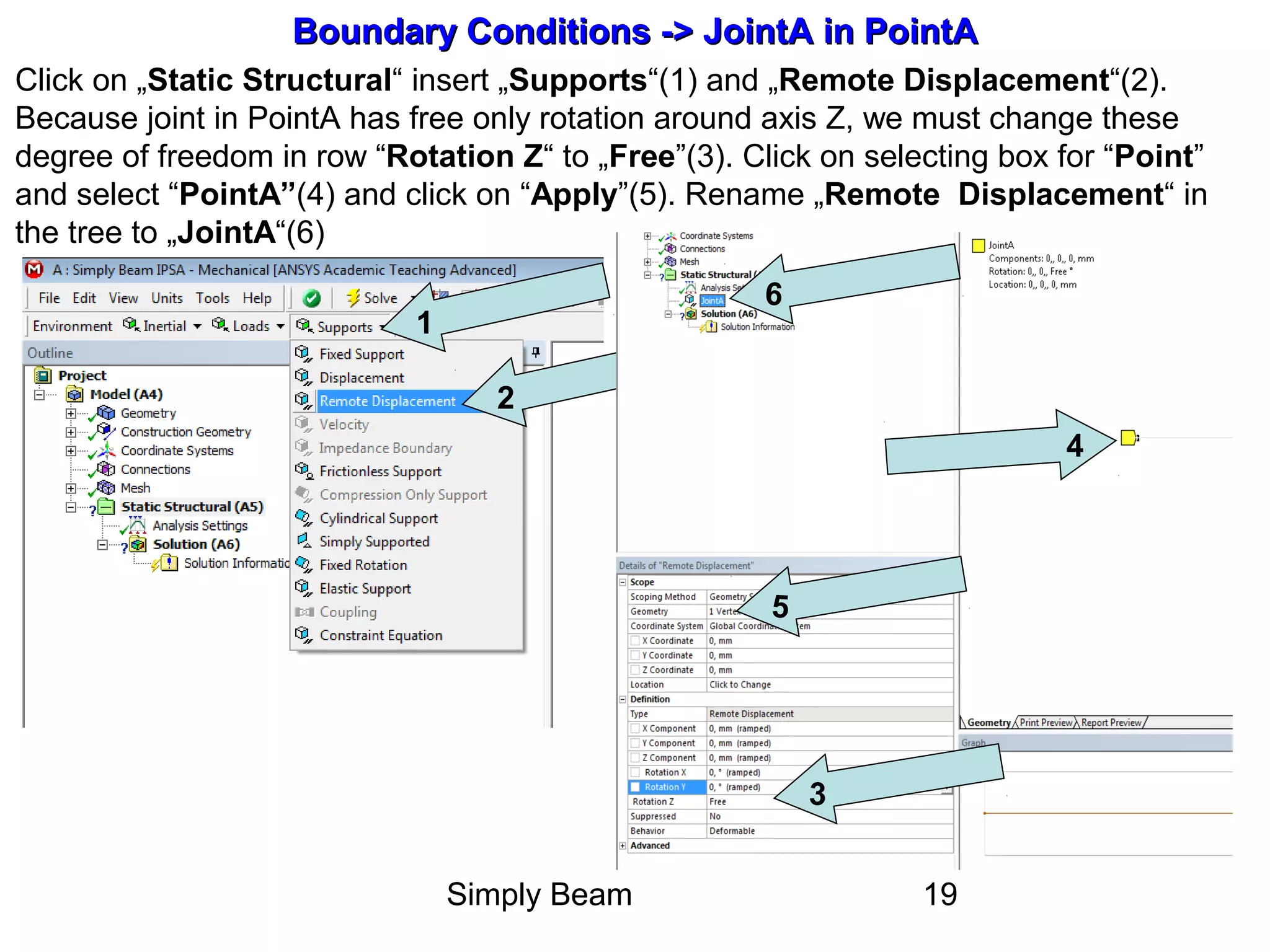
SlideShare a Scribd company logo
Static Analysis of Beam
by Finite Element Method
In Ansys Workbench version 13
HORYL Petr
Ostrava 2012
Simply Beam 2
Contents
• Open Static Structural
• Design Modeler (DM) – Geometry
• Model – input Geometry from DM,
Connections, Mesh
• Static Structural - Boundary Conditions
(Force, Moment, Line
Pressure, Joints)
• Solution – Results (Displacement, Internal
Forces, Stress…)
Simply Beam 3
Simply Beam StructureSimply Beam Structure
D d1
a) Maximum deflection
b) Course of internal forces - axial force, shearing force and bending moment
c) Maximum of normal stress
Cross-section of beam: D = 152 mm, d1 = 60 mm
Material properties: Steel Young's modulus of elasticity E = 2.1E5 MPa,
Poisson's ratio ν = 0.3
BA
6 m
q= 2.5 kN/m
M = 4 kNm
3 m
F= 3kN
α = 46o
5 m
C DPart1 Part2 Part3
Simply Beam 4
New ProjectNew Project
2
1
After starting the Workbench 13 select the type of analysis – „Static
Structural“(arrow No 1) and type new name of project (2)
Simply Beam 5
1
2
3
4
Material PropertiesMaterial Properties
In window „Engineering Data“ we choose „Click here to add a new material“ . Potom napíšeme
jméno nového materiálu „Beam Material “ (Arrow no 1) a výběrem „Isotropic Elasticity“ (2) jsme
vyzváni k zadání příslušných materiálových dat v nově se otevírající tabulce hodnot ve spodní
části okna (3.). Zpět se vrátíme příkazem „Return to Project“ (4.)
Simply Beam 6
Units „mm“Units „mm“
Now we can select „Units“ (1). For example „Metric“ with „mm“
(2)
1
2
Simply Beam 7
Open Geometry =Open Geometry =>> Window „Design Modeler“Window „Design Modeler“
For creation beam geometry you must click on row „Geometry“ (1). Name of
opening window will be „Design Modeler“
1
Simply Beam 8
1
2
3
Geometry - PointsGeometry - Points
In the next window „Geometry“ we start creation of the four point from A till D, see picture of beam.
Click on „Point“ (1), in the card below left choose „Manual Input“ (2), type “Coordinates X, Y, Z” of
the point (3) and click on “Generate”(4). You can “Rename”(5) Point1 to PointA. In the middle of
window you can see “PointA”(6). Repeat it for PointB to PointD.
4
5
6
Simply Beam 9
Geometry –Geometry – 44 PointsPoints
All 4 Points were created.
Simply Beam 10
1
2
3
4
5
Geometry –Geometry – LinesLines
Now we continue creation geometry namely lines. Click on „Concept“(1), in the menu top left
and choose „Lines From Points“(1). Hold “Ctrl“ keyboard button and select by left mouse
button “PointA”(2) and “PointC”(3). Confirm by mouse “Apply”(4) and click on “Generate”(5).
We have created Part1 of our beam. Repeat it for Part1 and Part2
Simply Beam 11
Geometry –Geometry – 3 Lines => Part1 to Part33 Lines => Part1 to Part3
All 3 Lines were created.
PointA
PointB
PointC
PointD
Part1
Part2
Part3
Simply Beam 12
Cross sectionCross section
1
2
3
4
5
Now we select cross section of our beam. Click on „Concept“(1), in the menu top left and
choose „Cross Section“(2) and “Circular Tube”(3). In the card below left, type outer “Ro“ and
internal “Ri” radius(4). In main window you see cross section(5).
Simply Beam 13
Cross section for our beamCross section for our beam
1
2
3
Click on „Line Body“(1), in the menu top left and choose „Cross Section“ and “Circular
Tube”(2). Confirm it by “Generation“(3). Save Project and Exit Design Modeler.
Simply Beam 14
Transition between GeometryTransition between Geometry and Modeland Model
For the correct transition between windows „Geometry“ and „Model“must be checked „Geometry
Import“. In our project window click on „Tools (1) – Options - Geometry Import (2)“ and check
tick box „Line Bodies“(3). Now open window „Model“ (4).
3
1
2
4
Simply Beam 15
Creation Path in Construction GeometryCreation Path in Construction Geometry
To plot internal forces in the beam-shaped „Shear Force - Bending Diagramm“, we must
choose on beam „Path“. In Modeler window click on „Model“(1), „Construction Geometry“(2) and
„Path“(3). Then change the „Details of Path“(4) for „Path Type“(5) on „Edge“(6).
4
5
6
1
2
3
3
Simply Beam 16
Creation Path in Construction Geometry - continueCreation Path in Construction Geometry - continue
Click on „Path“(1). Choose „Line“(2) in Selection boxes. Hold “Ctrl“ keyboard button
and select by left mouse button all three lines from left to right. Click on „Apply“(3).
1
2
3
Simply Beam 17
Creation Path in Construction Geometry - continueCreation Path in Construction Geometry - continue
We get right „Path“(1) for whole beam from starting „Edge“(2) to ending „Edge“(3)
1
2
3
Simply Beam 18
Mesh GenerationMesh Generation
Left mouse button click on „Mesh“(1), open „Element Size“(2) in Details of „Mesh“
and type 50mm (2). Click right mouse button again on Mesh and „Generate
Mesh“(3). Zoom right end of our beam and look at Circular Tube Cross Sections(4) .
1
2
3
4
Simply Beam 19
Boundary Conditions -Boundary Conditions -> Joint> JointAA in PointAin PointA
Click on „Static Structural“ insert „Supports“(1) and „Remote Displacement“(2).
Because joint in PointA has free only rotation around axis Z, we must change these
degree of freedom in row “Rotation Z“ to „Free”(3). Click on selecting box for “Point”
and select “PointA”(4) and click on “Apply”(5). Rename „Remote Displacement“ in
the tree to „JointA“(6)
1
2
3
4
5
6
Simply Beam 20
Boundary Conditions -Boundary Conditions -> Joint> JointAA in PointAin PointA continuecontinue
Picture shows only one free degree of freedom for JointA namely “Rotation: 0,, 0,,
Free”(1). Rename this row in tree to “JointA”(2).
1
2
Simply Beam 21
Boundary Conditions -Boundary Conditions -> Joint> JointBB in PointBin PointB
On the same way we create “JointB”(1), but here we have two Free degree of freedom :
“X Component - Free”(2) and “Rotation Z - Free”(3). We renamed joint to “PointB”(4)
1
2
4
3
Simply Beam 22
Boundary Conditions -Boundary Conditions -> Force, Moment and Line Pressure> Force, Moment and Line Pressure
Click right mouse button on “Static Structural – Insert”(1). In the next step, we will
need “Force”(2), “Moment”(3) and “Line Pressure”(4).
1
2
3
4
Simply Beam 23
Boundary Conditions -Boundary Conditions -> Force> Force
Click right mouse button on “Static Structural“(1) „Insert“(2) and „Force”(3).
2
3
1
Simply Beam 24
7
6
8
Boundary Conditions -Boundary Conditions -> Force> Force continuecontinue
In the left below table „Details of „Force“(1) change in row „Define by“ to „Components“(2).
Type -2084 into row „X Component“(3) e.g. FX=F*cos(alfa)= 3000*cos(46). Type -2158 into row „Y
Component“(4) e.g. FX=F*sin(alfa)=3000*sin(46). Click on selecting box for “Point”(6) and select
“PointD”(7) and click on “Apply”. In the middle of window you can notice red force vektor(8)
2
3
4
1
Simply Beam 25
Boundary Conditions -Boundary Conditions ->> MomentMoment
Similarly as Force, specify moment to „PointC“(1) as „Z Component“(2) -4E6 N.mm. In
the middle of window you can notice sense of bending moment M, drawn in red (1)
2
1
Simply Beam 26
Boundary Conditions -Boundary Conditions ->> Line PressureLine Pressure
Similarly as previous boundary conditions specify „Line Pressure“ on „Part2“(1). You
must select box „Line“(2) from selection boxes. Into table „Details of „Line Pressure“(3)
type -2,5 N/mm in row „Y Component“(4) and click on „Apply“(5).
2
1
3
4
5
Simply Beam 27
Boundary Conditions -Boundary Conditions ->> Line Pressure continueLine Pressure continue
In the middle of window you can notice red „Line Pressure“(1) with Y Component
-2,5 N/mm(2).
1
2
Simply Beam 28
All Boundary Conditions in one pictureAll Boundary Conditions in one picture
If you click on „Static Structural“ you can see all Boundary Conditions with their
values(1).
1
Simply Beam 29
SolutionSolution
Now befor Solution we must prepare results which we need for our example analysis.
It could be „Deformation“(1), „Beam Results“(2) for getting internal forces or „Beam
Tool“(3) for stress results.
1
2
3
Simply Beam 30
SolutionSolution
As you can see, we select: „Total Deformation“, „Axial Force“, „Total Shear
Force“, „Total Bending Moment“(1) and „Directional Shear-Moment Diagram
(VY-MZ-UY)“(2). Befor selecting row „Directional Shear-Moment Diagram (VY-
MZ-UY)“(2) in table „Details of …“, we must select in row „Path“ the same name
for our beam also „Path“(3).
1
2
3
Simply Beam 31
Solution – Beam Tool and Force ReactionSolution – Beam Tool and Force Reaction
We can add also: „Beam Tool“(1) with three possibility of resulting stress. „Direct
Stress“, „Minimum Combined Stress“ and „ Maximum Combined Stress“(2).
Important are also reaction forces. Click on „Probe“(3) and „Force Reaction“(4).
1
2
3
4
Simply Beam 32
Solution – Force Reaction continueSolution – Force Reaction continue
After clicking on „Probe“ and „Force Reaction“ select in table „Details of „Force
Reaction“(1) row „Boundary Condition - JointA“(2). After that you can see
small green table in the place of JointA „Force Reaction“(3). Do the same proces
for JointB.
1
2
3
Simply Beam 33
Solution - SolveSolution - Solve
1
Start computing proces with clicking on „Solve“(1)
Simply Beam 34
Results – Total DeformationResults – Total Deformation
Details on exercises
1
2
3
Simply Beam 35
Results – Total DeformationResults – Total Deformation
Simply Beam 36
Results – Axial ForceResults – Axial Force
Simply Beam 37
Results – Shear ForceResults – Shear Force
Simply Beam 38
Results – Bending MomentResults – Bending Moment
Simply Beam 39
Results – Axial SressResults – Axial Sress
Simply Beam 40
Results – Maximum Combined SressResults – Maximum Combined Sress
Simply Beam 41
Results – Shear-Moment-DiagramResults – Shear-Moment-Diagram
Simply Beam 42
Results – Force Reaction in JointAResults – Force Reaction in JointA
Simply Beam 43
Results – Force Reaction in JointBResults – Force Reaction in JointB

More Related Content

What's hot

Creo 3.0 whatsnew(PTC Creo 2.0 Enhancements)
Creo 3.0 whatsnew(PTC Creo 2.0 Enhancements)Creo 3.0 whatsnew(PTC Creo 2.0 Enhancements)
Creo 3.0 whatsnew(PTC Creo 2.0 Enhancements)
CY N
 
Eg5 n
Eg5 nEg5 n
Eg5 n
Parth Sahu
 
Autocad Training Delhi
Autocad Training DelhiAutocad Training Delhi
Autocad Training Delhi
lalit_625
 
AutoCAD Lesson coordinate system
AutoCAD Lesson coordinate systemAutoCAD Lesson coordinate system
AutoCAD Lesson coordinate system
Lordame Carmi Anda
 
13.50
13.5013.50
Worked examples for Cross section analysis and design software
Worked examples for Cross section analysis and design softwareWorked examples for Cross section analysis and design software
Worked examples for Cross section analysis and design software
George Nafpaktitis
 
Auto cad workbook2d hartnell college engineering technology
Auto cad workbook2d   hartnell college engineering technologyAuto cad workbook2d   hartnell college engineering technology
Auto cad workbook2d hartnell college engineering technology
AlFakir Fikri AlTakiri
 
Autocad map 3d tutorials
Autocad map 3d tutorialsAutocad map 3d tutorials
Autocad map 3d tutorials
Javier Morales
 
C3D Labs. Geometric Modeling Toolkit
C3D Labs. Geometric Modeling ToolkitC3D Labs. Geometric Modeling Toolkit
C3D Labs. Geometric Modeling Toolkit
Arkadiy Kamnev
 
3 d autocad_2009
3 d autocad_20093 d autocad_2009
3 d autocad_2009
Oscar Fuentes
 
Commands in AutoCAD
Commands in AutoCADCommands in AutoCAD
Commands in AutoCAD
Ravi Bhadauria
 
Tutorial for design of foundations using safe
Tutorial for design of foundations using safeTutorial for design of foundations using safe
Tutorial for design of foundations using safe
Asaye Dilbo
 
Auto cad 2020_shortcuts_guide
Auto cad 2020_shortcuts_guideAuto cad 2020_shortcuts_guide
Auto cad 2020_shortcuts_guide
AlFakir Fikri AlTakiri
 
AutoCAD 2D & 3D
AutoCAD 2D & 3DAutoCAD 2D & 3D
Creo parametric tips and tricks
Creo parametric tips and tricksCreo parametric tips and tricks
Creo parametric tips and tricks
Evan Winter
 
Presentation On Auto Cad
Presentation On Auto CadPresentation On Auto Cad
Presentation On Auto Cad
Vaibhav Gautam
 

What's hot (16)

Creo 3.0 whatsnew(PTC Creo 2.0 Enhancements)
Creo 3.0 whatsnew(PTC Creo 2.0 Enhancements)Creo 3.0 whatsnew(PTC Creo 2.0 Enhancements)
Creo 3.0 whatsnew(PTC Creo 2.0 Enhancements)
 
Eg5 n
Eg5 nEg5 n
Eg5 n
 
Autocad Training Delhi
Autocad Training DelhiAutocad Training Delhi
Autocad Training Delhi
 
AutoCAD Lesson coordinate system
AutoCAD Lesson coordinate systemAutoCAD Lesson coordinate system
AutoCAD Lesson coordinate system
 
13.50
13.5013.50
13.50
 
Worked examples for Cross section analysis and design software
Worked examples for Cross section analysis and design softwareWorked examples for Cross section analysis and design software
Worked examples for Cross section analysis and design software
 
Auto cad workbook2d hartnell college engineering technology
Auto cad workbook2d   hartnell college engineering technologyAuto cad workbook2d   hartnell college engineering technology
Auto cad workbook2d hartnell college engineering technology
 
Autocad map 3d tutorials
Autocad map 3d tutorialsAutocad map 3d tutorials
Autocad map 3d tutorials
 
C3D Labs. Geometric Modeling Toolkit
C3D Labs. Geometric Modeling ToolkitC3D Labs. Geometric Modeling Toolkit
C3D Labs. Geometric Modeling Toolkit
 
3 d autocad_2009
3 d autocad_20093 d autocad_2009
3 d autocad_2009
 
Commands in AutoCAD
Commands in AutoCADCommands in AutoCAD
Commands in AutoCAD
 
Tutorial for design of foundations using safe
Tutorial for design of foundations using safeTutorial for design of foundations using safe
Tutorial for design of foundations using safe
 
Auto cad 2020_shortcuts_guide
Auto cad 2020_shortcuts_guideAuto cad 2020_shortcuts_guide
Auto cad 2020_shortcuts_guide
 
AutoCAD 2D & 3D
AutoCAD 2D & 3DAutoCAD 2D & 3D
AutoCAD 2D & 3D
 
Creo parametric tips and tricks
Creo parametric tips and tricksCreo parametric tips and tricks
Creo parametric tips and tricks
 
Presentation On Auto Cad
Presentation On Auto CadPresentation On Auto Cad
Presentation On Auto Cad
 

Viewers also liked

Bons mots et belles phrases
Bons mots et belles phrasesBons mots et belles phrases
Bons mots et belles phrases
Albert Antebi
 
Finite element modelling of adhesive
Finite element modelling of adhesiveFinite element modelling of adhesive
Finite element modelling of adhesive
AHMET BENLİ
 
Dubai airports
Dubai airportsDubai airports
Dubai airports
Pamela Nazareth
 
Dubai Airports
Dubai AirportsDubai Airports
Dubai Airports
Richa Goel
 
Dubai Airport 2012 Data Center Strategies
Dubai Airport  2012 Data Center Strategies Dubai Airport  2012 Data Center Strategies
Dubai Airport 2012 Data Center Strategies
Sarmad Ibrahim
 
Finite Element Methode (FEM) Notes
Finite Element Methode (FEM) NotesFinite Element Methode (FEM) Notes
Finite Element Methode (FEM) Notes
Zulkifli Yunus
 
Finite Element Method
Finite Element MethodFinite Element Method
Finite Element Method
Muhammad Haris
 
Introduction to finite element analysis
Introduction to finite element analysisIntroduction to finite element analysis
Introduction to finite element analysis
Tarun Gehlot
 
Introduction to finite element method(fem)
Introduction to finite element method(fem)Introduction to finite element method(fem)
Introduction to finite element method(fem)
Sreekanth G
 
Book for Beginners, RCC Design by ETABS
Book for Beginners, RCC Design by ETABSBook for Beginners, RCC Design by ETABS
Book for Beginners, RCC Design by ETABS
Yousuf Dinar
 
Finite Element for Trusses in 2-D
Finite Element for Trusses in 2-DFinite Element for Trusses in 2-D
Finite Element for Trusses in 2-D
Mohammad Tawfik
 
Dubai Airport & City Guide
Dubai Airport & City GuideDubai Airport & City Guide

Viewers also liked (12)

Bons mots et belles phrases
Bons mots et belles phrasesBons mots et belles phrases
Bons mots et belles phrases
 
Finite element modelling of adhesive
Finite element modelling of adhesiveFinite element modelling of adhesive
Finite element modelling of adhesive
 
Dubai airports
Dubai airportsDubai airports
Dubai airports
 
Dubai Airports
Dubai AirportsDubai Airports
Dubai Airports
 
Dubai Airport 2012 Data Center Strategies
Dubai Airport  2012 Data Center Strategies Dubai Airport  2012 Data Center Strategies
Dubai Airport 2012 Data Center Strategies
 
Finite Element Methode (FEM) Notes
Finite Element Methode (FEM) NotesFinite Element Methode (FEM) Notes
Finite Element Methode (FEM) Notes
 
Finite Element Method
Finite Element MethodFinite Element Method
Finite Element Method
 
Introduction to finite element analysis
Introduction to finite element analysisIntroduction to finite element analysis
Introduction to finite element analysis
 
Introduction to finite element method(fem)
Introduction to finite element method(fem)Introduction to finite element method(fem)
Introduction to finite element method(fem)
 
Book for Beginners, RCC Design by ETABS
Book for Beginners, RCC Design by ETABSBook for Beginners, RCC Design by ETABS
Book for Beginners, RCC Design by ETABS
 
Finite Element for Trusses in 2-D
Finite Element for Trusses in 2-DFinite Element for Trusses in 2-D
Finite Element for Trusses in 2-D
 
Dubai Airport & City Guide
Dubai Airport & City GuideDubai Airport & City Guide
Dubai Airport & City Guide
 

Similar to Beam workbench13

3 d autocad
3 d autocad3 d autocad
3 d autocad
Cleverson Leite
 
3 d autocad
3 d autocad3 d autocad
3 d autocad
danny perez
 
AutoCAD - 3D Notes
AutoCAD - 3D NotesAutoCAD - 3D Notes
AutoCAD - 3D Notes
Vj NiroSh
 
3D_AutoCAD.pdf
3D_AutoCAD.pdf3D_AutoCAD.pdf
3D_AutoCAD.pdf
azliana33k
 
Baja example
Baja exampleBaja example
3 d autocad_2009
3 d autocad_20093 d autocad_2009
3 d autocad_2009
Yayuk Setiyowati
 
AutoCAD-ppt.pptx
AutoCAD-ppt.pptxAutoCAD-ppt.pptx
AutoCAD-ppt.pptx
ABUFAZZIL
 
Auto cad tutorial
Auto cad tutorialAuto cad tutorial
Auto cad tutorial
Felix Lidoro
 
AutoCAD-ppt_ training report summer .pptx
AutoCAD-ppt_ training report summer .pptxAutoCAD-ppt_ training report summer .pptx
AutoCAD-ppt_ training report summer .pptx
AbhiSuman2
 
AutoCAD-ppt.pptx
AutoCAD-ppt.pptxAutoCAD-ppt.pptx
AutoCAD-ppt.pptx
ArunKumar863577
 
AutoCAD-ppt.pptx
AutoCAD-ppt.pptxAutoCAD-ppt.pptx
AutoCAD-ppt.pptx
Madhu797724
 
Modeling seismic analysis_and_design_of_rc_building_10_story
Modeling seismic analysis_and_design_of_rc_building_10_storyModeling seismic analysis_and_design_of_rc_building_10_story
Modeling seismic analysis_and_design_of_rc_building_10_story
AliAlmayalee
 
presentationprintTemp.ppt auto cad presentation
presentationprintTemp.ppt auto cad presentationpresentationprintTemp.ppt auto cad presentation
presentationprintTemp.ppt auto cad presentation
vikramchandrachoudha
 
CAD Lab Manual 2021-22 pdf-30-51.pdf
CAD Lab Manual  2021-22 pdf-30-51.pdfCAD Lab Manual  2021-22 pdf-30-51.pdf
CAD Lab Manual 2021-22 pdf-30-51.pdf
Sunil Jp
 
mech AutoCAD ppt.pptx
mech AutoCAD ppt.pptxmech AutoCAD ppt.pptx
mech AutoCAD ppt.pptx
Harish181
 
ME252-MechanicalEngineeringDrawing.pptx
ME252-MechanicalEngineeringDrawing.pptxME252-MechanicalEngineeringDrawing.pptx
ME252-MechanicalEngineeringDrawing.pptx
ZeinaKotb
 
3 d auto cad 2009
3 d auto cad 20093 d auto cad 2009
3 d auto cad 2009
thuonglindo
 
3 d autocad_2009
3 d autocad_20093 d autocad_2009
3 d autocad_2009
miguel70919
 
3 d autocad_2009
3 d autocad_20093 d autocad_2009
3 d autocad_2009
ricardovigan
 
3 d autocad_2009
3 d autocad_20093 d autocad_2009
3 d autocad_2009
Jo Padilha
 

Similar to Beam workbench13 (20)

3 d autocad
3 d autocad3 d autocad
3 d autocad
 
3 d autocad
3 d autocad3 d autocad
3 d autocad
 
AutoCAD - 3D Notes
AutoCAD - 3D NotesAutoCAD - 3D Notes
AutoCAD - 3D Notes
 
3D_AutoCAD.pdf
3D_AutoCAD.pdf3D_AutoCAD.pdf
3D_AutoCAD.pdf
 
Baja example
Baja exampleBaja example
Baja example
 
3 d autocad_2009
3 d autocad_20093 d autocad_2009
3 d autocad_2009
 
AutoCAD-ppt.pptx
AutoCAD-ppt.pptxAutoCAD-ppt.pptx
AutoCAD-ppt.pptx
 
Auto cad tutorial
Auto cad tutorialAuto cad tutorial
Auto cad tutorial
 
AutoCAD-ppt_ training report summer .pptx
AutoCAD-ppt_ training report summer .pptxAutoCAD-ppt_ training report summer .pptx
AutoCAD-ppt_ training report summer .pptx
 
AutoCAD-ppt.pptx
AutoCAD-ppt.pptxAutoCAD-ppt.pptx
AutoCAD-ppt.pptx
 
AutoCAD-ppt.pptx
AutoCAD-ppt.pptxAutoCAD-ppt.pptx
AutoCAD-ppt.pptx
 
Modeling seismic analysis_and_design_of_rc_building_10_story
Modeling seismic analysis_and_design_of_rc_building_10_storyModeling seismic analysis_and_design_of_rc_building_10_story
Modeling seismic analysis_and_design_of_rc_building_10_story
 
presentationprintTemp.ppt auto cad presentation
presentationprintTemp.ppt auto cad presentationpresentationprintTemp.ppt auto cad presentation
presentationprintTemp.ppt auto cad presentation
 
CAD Lab Manual 2021-22 pdf-30-51.pdf
CAD Lab Manual  2021-22 pdf-30-51.pdfCAD Lab Manual  2021-22 pdf-30-51.pdf
CAD Lab Manual 2021-22 pdf-30-51.pdf
 
mech AutoCAD ppt.pptx
mech AutoCAD ppt.pptxmech AutoCAD ppt.pptx
mech AutoCAD ppt.pptx
 
ME252-MechanicalEngineeringDrawing.pptx
ME252-MechanicalEngineeringDrawing.pptxME252-MechanicalEngineeringDrawing.pptx
ME252-MechanicalEngineeringDrawing.pptx
 
3 d auto cad 2009
3 d auto cad 20093 d auto cad 2009
3 d auto cad 2009
 
3 d autocad_2009
3 d autocad_20093 d autocad_2009
3 d autocad_2009
 
3 d autocad_2009
3 d autocad_20093 d autocad_2009
3 d autocad_2009
 
3 d autocad_2009
3 d autocad_20093 d autocad_2009
3 d autocad_2009
 

Recently uploaded

Redefining brain tumor segmentation: a cutting-edge convolutional neural netw...
Redefining brain tumor segmentation: a cutting-edge convolutional neural netw...Redefining brain tumor segmentation: a cutting-edge convolutional neural netw...
Redefining brain tumor segmentation: a cutting-edge convolutional neural netw...
IJECEIAES
 
Engineering Drawings Lecture Detail Drawings 2014.pdf
Engineering Drawings Lecture Detail Drawings 2014.pdfEngineering Drawings Lecture Detail Drawings 2014.pdf
Engineering Drawings Lecture Detail Drawings 2014.pdf
abbyasa1014
 
Computational Engineering IITH Presentation
Computational Engineering IITH PresentationComputational Engineering IITH Presentation
Computational Engineering IITH Presentation
co23btech11018
 
KuberTENes Birthday Bash Guadalajara - K8sGPT first impressions
KuberTENes Birthday Bash Guadalajara - K8sGPT first impressionsKuberTENes Birthday Bash Guadalajara - K8sGPT first impressions
KuberTENes Birthday Bash Guadalajara - K8sGPT first impressions
Victor Morales
 
Electric vehicle and photovoltaic advanced roles in enhancing the financial p...
Electric vehicle and photovoltaic advanced roles in enhancing the financial p...Electric vehicle and photovoltaic advanced roles in enhancing the financial p...
Electric vehicle and photovoltaic advanced roles in enhancing the financial p...
IJECEIAES
 
TIME DIVISION MULTIPLEXING TECHNIQUE FOR COMMUNICATION SYSTEM
TIME DIVISION MULTIPLEXING TECHNIQUE FOR COMMUNICATION SYSTEMTIME DIVISION MULTIPLEXING TECHNIQUE FOR COMMUNICATION SYSTEM
TIME DIVISION MULTIPLEXING TECHNIQUE FOR COMMUNICATION SYSTEM
HODECEDSIET
 
Casting-Defect-inSlab continuous casting.pdf
Casting-Defect-inSlab continuous casting.pdfCasting-Defect-inSlab continuous casting.pdf
Casting-Defect-inSlab continuous casting.pdf
zubairahmad848137
 
A review on techniques and modelling methodologies used for checking electrom...
A review on techniques and modelling methodologies used for checking electrom...A review on techniques and modelling methodologies used for checking electrom...
A review on techniques and modelling methodologies used for checking electrom...
nooriasukmaningtyas
 
New techniques for characterising damage in rock slopes.pdf
New techniques for characterising damage in rock slopes.pdfNew techniques for characterising damage in rock slopes.pdf
New techniques for characterising damage in rock slopes.pdf
wisnuprabawa3
 
basic-wireline-operations-course-mahmoud-f-radwan.pdf
basic-wireline-operations-course-mahmoud-f-radwan.pdfbasic-wireline-operations-course-mahmoud-f-radwan.pdf
basic-wireline-operations-course-mahmoud-f-radwan.pdf
NidhalKahouli2
 
spirit beverages ppt without graphics.pptx
spirit beverages ppt without graphics.pptxspirit beverages ppt without graphics.pptx
spirit beverages ppt without graphics.pptx
Madan Karki
 
Eric Nizeyimana's document 2006 from gicumbi to ttc nyamata handball play
Eric Nizeyimana's document 2006 from gicumbi to ttc nyamata handball playEric Nizeyimana's document 2006 from gicumbi to ttc nyamata handball play
Eric Nizeyimana's document 2006 from gicumbi to ttc nyamata handball play
enizeyimana36
 
The Python for beginners. This is an advance computer language.
The Python for beginners. This is an advance computer language.The Python for beginners. This is an advance computer language.
The Python for beginners. This is an advance computer language.
sachin chaurasia
 
Embedded machine learning-based road conditions and driving behavior monitoring
Embedded machine learning-based road conditions and driving behavior monitoringEmbedded machine learning-based road conditions and driving behavior monitoring
Embedded machine learning-based road conditions and driving behavior monitoring
IJECEIAES
 
Heat Resistant Concrete Presentation ppt
Heat Resistant Concrete Presentation pptHeat Resistant Concrete Presentation ppt
Heat Resistant Concrete Presentation ppt
mamunhossenbd75
 
Advanced control scheme of doubly fed induction generator for wind turbine us...
Advanced control scheme of doubly fed induction generator for wind turbine us...Advanced control scheme of doubly fed induction generator for wind turbine us...
Advanced control scheme of doubly fed induction generator for wind turbine us...
IJECEIAES
 
Harnessing WebAssembly for Real-time Stateless Streaming Pipelines
Harnessing WebAssembly for Real-time Stateless Streaming PipelinesHarnessing WebAssembly for Real-time Stateless Streaming Pipelines
Harnessing WebAssembly for Real-time Stateless Streaming Pipelines
Christina Lin
 
ISPM 15 Heat Treated Wood Stamps and why your shipping must have one
ISPM 15 Heat Treated Wood Stamps and why your shipping must have oneISPM 15 Heat Treated Wood Stamps and why your shipping must have one
ISPM 15 Heat Treated Wood Stamps and why your shipping must have one
Las Vegas Warehouse
 
22CYT12-Unit-V-E Waste and its Management.ppt
22CYT12-Unit-V-E Waste and its Management.ppt22CYT12-Unit-V-E Waste and its Management.ppt
22CYT12-Unit-V-E Waste and its Management.ppt
KrishnaveniKrishnara1
 
Unit-III-ELECTROCHEMICAL STORAGE DEVICES.ppt
Unit-III-ELECTROCHEMICAL STORAGE DEVICES.pptUnit-III-ELECTROCHEMICAL STORAGE DEVICES.ppt
Unit-III-ELECTROCHEMICAL STORAGE DEVICES.ppt
KrishnaveniKrishnara1
 

Recently uploaded (20)

Redefining brain tumor segmentation: a cutting-edge convolutional neural netw...
Redefining brain tumor segmentation: a cutting-edge convolutional neural netw...Redefining brain tumor segmentation: a cutting-edge convolutional neural netw...
Redefining brain tumor segmentation: a cutting-edge convolutional neural netw...
 
Engineering Drawings Lecture Detail Drawings 2014.pdf
Engineering Drawings Lecture Detail Drawings 2014.pdfEngineering Drawings Lecture Detail Drawings 2014.pdf
Engineering Drawings Lecture Detail Drawings 2014.pdf
 
Computational Engineering IITH Presentation
Computational Engineering IITH PresentationComputational Engineering IITH Presentation
Computational Engineering IITH Presentation
 
KuberTENes Birthday Bash Guadalajara - K8sGPT first impressions
KuberTENes Birthday Bash Guadalajara - K8sGPT first impressionsKuberTENes Birthday Bash Guadalajara - K8sGPT first impressions
KuberTENes Birthday Bash Guadalajara - K8sGPT first impressions
 
Electric vehicle and photovoltaic advanced roles in enhancing the financial p...
Electric vehicle and photovoltaic advanced roles in enhancing the financial p...Electric vehicle and photovoltaic advanced roles in enhancing the financial p...
Electric vehicle and photovoltaic advanced roles in enhancing the financial p...
 
TIME DIVISION MULTIPLEXING TECHNIQUE FOR COMMUNICATION SYSTEM
TIME DIVISION MULTIPLEXING TECHNIQUE FOR COMMUNICATION SYSTEMTIME DIVISION MULTIPLEXING TECHNIQUE FOR COMMUNICATION SYSTEM
TIME DIVISION MULTIPLEXING TECHNIQUE FOR COMMUNICATION SYSTEM
 
Casting-Defect-inSlab continuous casting.pdf
Casting-Defect-inSlab continuous casting.pdfCasting-Defect-inSlab continuous casting.pdf
Casting-Defect-inSlab continuous casting.pdf
 
A review on techniques and modelling methodologies used for checking electrom...
A review on techniques and modelling methodologies used for checking electrom...A review on techniques and modelling methodologies used for checking electrom...
A review on techniques and modelling methodologies used for checking electrom...
 
New techniques for characterising damage in rock slopes.pdf
New techniques for characterising damage in rock slopes.pdfNew techniques for characterising damage in rock slopes.pdf
New techniques for characterising damage in rock slopes.pdf
 
basic-wireline-operations-course-mahmoud-f-radwan.pdf
basic-wireline-operations-course-mahmoud-f-radwan.pdfbasic-wireline-operations-course-mahmoud-f-radwan.pdf
basic-wireline-operations-course-mahmoud-f-radwan.pdf
 
spirit beverages ppt without graphics.pptx
spirit beverages ppt without graphics.pptxspirit beverages ppt without graphics.pptx
spirit beverages ppt without graphics.pptx
 
Eric Nizeyimana's document 2006 from gicumbi to ttc nyamata handball play
Eric Nizeyimana's document 2006 from gicumbi to ttc nyamata handball playEric Nizeyimana's document 2006 from gicumbi to ttc nyamata handball play
Eric Nizeyimana's document 2006 from gicumbi to ttc nyamata handball play
 
The Python for beginners. This is an advance computer language.
The Python for beginners. This is an advance computer language.The Python for beginners. This is an advance computer language.
The Python for beginners. This is an advance computer language.
 
Embedded machine learning-based road conditions and driving behavior monitoring
Embedded machine learning-based road conditions and driving behavior monitoringEmbedded machine learning-based road conditions and driving behavior monitoring
Embedded machine learning-based road conditions and driving behavior monitoring
 
Heat Resistant Concrete Presentation ppt
Heat Resistant Concrete Presentation pptHeat Resistant Concrete Presentation ppt
Heat Resistant Concrete Presentation ppt
 
Advanced control scheme of doubly fed induction generator for wind turbine us...
Advanced control scheme of doubly fed induction generator for wind turbine us...Advanced control scheme of doubly fed induction generator for wind turbine us...
Advanced control scheme of doubly fed induction generator for wind turbine us...
 
Harnessing WebAssembly for Real-time Stateless Streaming Pipelines
Harnessing WebAssembly for Real-time Stateless Streaming PipelinesHarnessing WebAssembly for Real-time Stateless Streaming Pipelines
Harnessing WebAssembly for Real-time Stateless Streaming Pipelines
 
ISPM 15 Heat Treated Wood Stamps and why your shipping must have one
ISPM 15 Heat Treated Wood Stamps and why your shipping must have oneISPM 15 Heat Treated Wood Stamps and why your shipping must have one
ISPM 15 Heat Treated Wood Stamps and why your shipping must have one
 
22CYT12-Unit-V-E Waste and its Management.ppt
22CYT12-Unit-V-E Waste and its Management.ppt22CYT12-Unit-V-E Waste and its Management.ppt
22CYT12-Unit-V-E Waste and its Management.ppt
 
Unit-III-ELECTROCHEMICAL STORAGE DEVICES.ppt
Unit-III-ELECTROCHEMICAL STORAGE DEVICES.pptUnit-III-ELECTROCHEMICAL STORAGE DEVICES.ppt
Unit-III-ELECTROCHEMICAL STORAGE DEVICES.ppt
 

Beam workbench13

  • 1. Static Analysis of Beam by Finite Element Method In Ansys Workbench version 13 HORYL Petr Ostrava 2012
  • 2. Simply Beam 2 Contents • Open Static Structural • Design Modeler (DM) – Geometry • Model – input Geometry from DM, Connections, Mesh • Static Structural - Boundary Conditions (Force, Moment, Line Pressure, Joints) • Solution – Results (Displacement, Internal Forces, Stress…)
  • 3. Simply Beam 3 Simply Beam StructureSimply Beam Structure D d1 a) Maximum deflection b) Course of internal forces - axial force, shearing force and bending moment c) Maximum of normal stress Cross-section of beam: D = 152 mm, d1 = 60 mm Material properties: Steel Young's modulus of elasticity E = 2.1E5 MPa, Poisson's ratio ν = 0.3 BA 6 m q= 2.5 kN/m M = 4 kNm 3 m F= 3kN α = 46o 5 m C DPart1 Part2 Part3
  • 4. Simply Beam 4 New ProjectNew Project 2 1 After starting the Workbench 13 select the type of analysis – „Static Structural“(arrow No 1) and type new name of project (2)
  • 5. Simply Beam 5 1 2 3 4 Material PropertiesMaterial Properties In window „Engineering Data“ we choose „Click here to add a new material“ . Potom napíšeme jméno nového materiálu „Beam Material “ (Arrow no 1) a výběrem „Isotropic Elasticity“ (2) jsme vyzváni k zadání příslušných materiálových dat v nově se otevírající tabulce hodnot ve spodní části okna (3.). Zpět se vrátíme příkazem „Return to Project“ (4.)
  • 6. Simply Beam 6 Units „mm“Units „mm“ Now we can select „Units“ (1). For example „Metric“ with „mm“ (2) 1 2
  • 7. Simply Beam 7 Open Geometry =Open Geometry =>> Window „Design Modeler“Window „Design Modeler“ For creation beam geometry you must click on row „Geometry“ (1). Name of opening window will be „Design Modeler“ 1
  • 8. Simply Beam 8 1 2 3 Geometry - PointsGeometry - Points In the next window „Geometry“ we start creation of the four point from A till D, see picture of beam. Click on „Point“ (1), in the card below left choose „Manual Input“ (2), type “Coordinates X, Y, Z” of the point (3) and click on “Generate”(4). You can “Rename”(5) Point1 to PointA. In the middle of window you can see “PointA”(6). Repeat it for PointB to PointD. 4 5 6
  • 9. Simply Beam 9 Geometry –Geometry – 44 PointsPoints All 4 Points were created.
  • 10. Simply Beam 10 1 2 3 4 5 Geometry –Geometry – LinesLines Now we continue creation geometry namely lines. Click on „Concept“(1), in the menu top left and choose „Lines From Points“(1). Hold “Ctrl“ keyboard button and select by left mouse button “PointA”(2) and “PointC”(3). Confirm by mouse “Apply”(4) and click on “Generate”(5). We have created Part1 of our beam. Repeat it for Part1 and Part2
  • 11. Simply Beam 11 Geometry –Geometry – 3 Lines => Part1 to Part33 Lines => Part1 to Part3 All 3 Lines were created. PointA PointB PointC PointD Part1 Part2 Part3
  • 12. Simply Beam 12 Cross sectionCross section 1 2 3 4 5 Now we select cross section of our beam. Click on „Concept“(1), in the menu top left and choose „Cross Section“(2) and “Circular Tube”(3). In the card below left, type outer “Ro“ and internal “Ri” radius(4). In main window you see cross section(5).
  • 13. Simply Beam 13 Cross section for our beamCross section for our beam 1 2 3 Click on „Line Body“(1), in the menu top left and choose „Cross Section“ and “Circular Tube”(2). Confirm it by “Generation“(3). Save Project and Exit Design Modeler.
  • 14. Simply Beam 14 Transition between GeometryTransition between Geometry and Modeland Model For the correct transition between windows „Geometry“ and „Model“must be checked „Geometry Import“. In our project window click on „Tools (1) – Options - Geometry Import (2)“ and check tick box „Line Bodies“(3). Now open window „Model“ (4). 3 1 2 4
  • 15. Simply Beam 15 Creation Path in Construction GeometryCreation Path in Construction Geometry To plot internal forces in the beam-shaped „Shear Force - Bending Diagramm“, we must choose on beam „Path“. In Modeler window click on „Model“(1), „Construction Geometry“(2) and „Path“(3). Then change the „Details of Path“(4) for „Path Type“(5) on „Edge“(6). 4 5 6 1 2 3 3
  • 16. Simply Beam 16 Creation Path in Construction Geometry - continueCreation Path in Construction Geometry - continue Click on „Path“(1). Choose „Line“(2) in Selection boxes. Hold “Ctrl“ keyboard button and select by left mouse button all three lines from left to right. Click on „Apply“(3). 1 2 3
  • 17. Simply Beam 17 Creation Path in Construction Geometry - continueCreation Path in Construction Geometry - continue We get right „Path“(1) for whole beam from starting „Edge“(2) to ending „Edge“(3) 1 2 3
  • 18. Simply Beam 18 Mesh GenerationMesh Generation Left mouse button click on „Mesh“(1), open „Element Size“(2) in Details of „Mesh“ and type 50mm (2). Click right mouse button again on Mesh and „Generate Mesh“(3). Zoom right end of our beam and look at Circular Tube Cross Sections(4) . 1 2 3 4
  • 19. Simply Beam 19 Boundary Conditions -Boundary Conditions -> Joint> JointAA in PointAin PointA Click on „Static Structural“ insert „Supports“(1) and „Remote Displacement“(2). Because joint in PointA has free only rotation around axis Z, we must change these degree of freedom in row “Rotation Z“ to „Free”(3). Click on selecting box for “Point” and select “PointA”(4) and click on “Apply”(5). Rename „Remote Displacement“ in the tree to „JointA“(6) 1 2 3 4 5 6
  • 20. Simply Beam 20 Boundary Conditions -Boundary Conditions -> Joint> JointAA in PointAin PointA continuecontinue Picture shows only one free degree of freedom for JointA namely “Rotation: 0,, 0,, Free”(1). Rename this row in tree to “JointA”(2). 1 2
  • 21. Simply Beam 21 Boundary Conditions -Boundary Conditions -> Joint> JointBB in PointBin PointB On the same way we create “JointB”(1), but here we have two Free degree of freedom : “X Component - Free”(2) and “Rotation Z - Free”(3). We renamed joint to “PointB”(4) 1 2 4 3
  • 22. Simply Beam 22 Boundary Conditions -Boundary Conditions -> Force, Moment and Line Pressure> Force, Moment and Line Pressure Click right mouse button on “Static Structural – Insert”(1). In the next step, we will need “Force”(2), “Moment”(3) and “Line Pressure”(4). 1 2 3 4
  • 23. Simply Beam 23 Boundary Conditions -Boundary Conditions -> Force> Force Click right mouse button on “Static Structural“(1) „Insert“(2) and „Force”(3). 2 3 1
  • 24. Simply Beam 24 7 6 8 Boundary Conditions -Boundary Conditions -> Force> Force continuecontinue In the left below table „Details of „Force“(1) change in row „Define by“ to „Components“(2). Type -2084 into row „X Component“(3) e.g. FX=F*cos(alfa)= 3000*cos(46). Type -2158 into row „Y Component“(4) e.g. FX=F*sin(alfa)=3000*sin(46). Click on selecting box for “Point”(6) and select “PointD”(7) and click on “Apply”. In the middle of window you can notice red force vektor(8) 2 3 4 1
  • 25. Simply Beam 25 Boundary Conditions -Boundary Conditions ->> MomentMoment Similarly as Force, specify moment to „PointC“(1) as „Z Component“(2) -4E6 N.mm. In the middle of window you can notice sense of bending moment M, drawn in red (1) 2 1
  • 26. Simply Beam 26 Boundary Conditions -Boundary Conditions ->> Line PressureLine Pressure Similarly as previous boundary conditions specify „Line Pressure“ on „Part2“(1). You must select box „Line“(2) from selection boxes. Into table „Details of „Line Pressure“(3) type -2,5 N/mm in row „Y Component“(4) and click on „Apply“(5). 2 1 3 4 5
  • 27. Simply Beam 27 Boundary Conditions -Boundary Conditions ->> Line Pressure continueLine Pressure continue In the middle of window you can notice red „Line Pressure“(1) with Y Component -2,5 N/mm(2). 1 2
  • 28. Simply Beam 28 All Boundary Conditions in one pictureAll Boundary Conditions in one picture If you click on „Static Structural“ you can see all Boundary Conditions with their values(1). 1
  • 29. Simply Beam 29 SolutionSolution Now befor Solution we must prepare results which we need for our example analysis. It could be „Deformation“(1), „Beam Results“(2) for getting internal forces or „Beam Tool“(3) for stress results. 1 2 3
  • 30. Simply Beam 30 SolutionSolution As you can see, we select: „Total Deformation“, „Axial Force“, „Total Shear Force“, „Total Bending Moment“(1) and „Directional Shear-Moment Diagram (VY-MZ-UY)“(2). Befor selecting row „Directional Shear-Moment Diagram (VY- MZ-UY)“(2) in table „Details of …“, we must select in row „Path“ the same name for our beam also „Path“(3). 1 2 3
  • 31. Simply Beam 31 Solution – Beam Tool and Force ReactionSolution – Beam Tool and Force Reaction We can add also: „Beam Tool“(1) with three possibility of resulting stress. „Direct Stress“, „Minimum Combined Stress“ and „ Maximum Combined Stress“(2). Important are also reaction forces. Click on „Probe“(3) and „Force Reaction“(4). 1 2 3 4
  • 32. Simply Beam 32 Solution – Force Reaction continueSolution – Force Reaction continue After clicking on „Probe“ and „Force Reaction“ select in table „Details of „Force Reaction“(1) row „Boundary Condition - JointA“(2). After that you can see small green table in the place of JointA „Force Reaction“(3). Do the same proces for JointB. 1 2 3
  • 33. Simply Beam 33 Solution - SolveSolution - Solve 1 Start computing proces with clicking on „Solve“(1)
  • 34. Simply Beam 34 Results – Total DeformationResults – Total Deformation Details on exercises 1 2 3
  • 35. Simply Beam 35 Results – Total DeformationResults – Total Deformation
  • 36. Simply Beam 36 Results – Axial ForceResults – Axial Force
  • 37. Simply Beam 37 Results – Shear ForceResults – Shear Force
  • 38. Simply Beam 38 Results – Bending MomentResults – Bending Moment
  • 39. Simply Beam 39 Results – Axial SressResults – Axial Sress
  • 40. Simply Beam 40 Results – Maximum Combined SressResults – Maximum Combined Sress
  • 41. Simply Beam 41 Results – Shear-Moment-DiagramResults – Shear-Moment-Diagram
  • 42. Simply Beam 42 Results – Force Reaction in JointAResults – Force Reaction in JointA
  • 43. Simply Beam 43 Results – Force Reaction in JointBResults – Force Reaction in JointB