The document discusses various modulation techniques including:
- Amplitude modulation (AM) which varies the amplitude of a carrier signal by a message signal. It results in double sideband modulation with upper and lower sidebands.
- Digital modulation techniques for binary signals including amplitude-shift keying (ASK), frequency-shift keying (FSK), and phase-shift keying (PSK).
- Multi-level modulation generalizes the above to multiple levels like quadrature phase-shift keying (QPSK) and M-ary modulation.
The following resources come from the 2009/10 BEng (Hons) in Digital Communications & Electronics (course number 2ELE0064) from the University of Hertfordshire. All the mini projects are designed as level two modules of the undergraduate programmes.
The objective of this module is to have built communication links using existing AM modulation, PSK modulation and demodulation blocks, constructed AM modulators and constructed PSK modulators using operational function blocks based on their mathematical expressions, and conducted simulations of the links and modulators, all in Simulink®.
AM modulation and Demodulation with Circuit and OutputSovan Paul
Here we use IC8038 as a signal generator to generate modulating and carrier signal. IC1496 a Balance Modulator IC used for modulation purpose, for demodulation purpose simple Diode Detector(Envelop type) is used.
This presentation include the basic concept of communication, modulation techniques in analog and digital. ADC (Analog to Digital Conversion) and Demodulation schemes
Comparative Study and Performance Analysis of different Modulation Techniques...Souvik Das
A comparative study and performance analysis of different modulation
techniques which shows graphically and comparative results Channel Noise
with Bit Error Rate of ASK, FSK, PSK and QPSK.
COLLEGE BUS MANAGEMENT SYSTEM PROJECT REPORT.pdfKamal Acharya
The College Bus Management system is completely developed by Visual Basic .NET Version. The application is connect with most secured database language MS SQL Server. The application is develop by using best combination of front-end and back-end languages. The application is totally design like flat user interface. This flat user interface is more attractive user interface in 2017. The application is gives more important to the system functionality. The application is to manage the student’s details, driver’s details, bus details, bus route details, bus fees details and more. The application has only one unit for admin. The admin can manage the entire application. The admin can login into the application by using username and password of the admin. The application is develop for big and small colleges. It is more user friendly for non-computer person. Even they can easily learn how to manage the application within hours. The application is more secure by the admin. The system will give an effective output for the VB.Net and SQL Server given as input to the system. The compiled java program given as input to the system, after scanning the program will generate different reports. The application generates the report for users. The admin can view and download the report of the data. The application deliver the excel format reports. Because, excel formatted reports is very easy to understand the income and expense of the college bus. This application is mainly develop for windows operating system users. In 2017, 73% of people enterprises are using windows operating system. So the application will easily install for all the windows operating system users. The application-developed size is very low. The application consumes very low space in disk. Therefore, the user can allocate very minimum local disk space for this application.
More Related Content
Similar to Introduction to Modulation and Demodulation.ppt
The following resources come from the 2009/10 BEng (Hons) in Digital Communications & Electronics (course number 2ELE0064) from the University of Hertfordshire. All the mini projects are designed as level two modules of the undergraduate programmes.
The objective of this module is to have built communication links using existing AM modulation, PSK modulation and demodulation blocks, constructed AM modulators and constructed PSK modulators using operational function blocks based on their mathematical expressions, and conducted simulations of the links and modulators, all in Simulink®.
AM modulation and Demodulation with Circuit and OutputSovan Paul
Here we use IC8038 as a signal generator to generate modulating and carrier signal. IC1496 a Balance Modulator IC used for modulation purpose, for demodulation purpose simple Diode Detector(Envelop type) is used.
This presentation include the basic concept of communication, modulation techniques in analog and digital. ADC (Analog to Digital Conversion) and Demodulation schemes
Comparative Study and Performance Analysis of different Modulation Techniques...Souvik Das
A comparative study and performance analysis of different modulation
techniques which shows graphically and comparative results Channel Noise
with Bit Error Rate of ASK, FSK, PSK and QPSK.
COLLEGE BUS MANAGEMENT SYSTEM PROJECT REPORT.pdfKamal Acharya
The College Bus Management system is completely developed by Visual Basic .NET Version. The application is connect with most secured database language MS SQL Server. The application is develop by using best combination of front-end and back-end languages. The application is totally design like flat user interface. This flat user interface is more attractive user interface in 2017. The application is gives more important to the system functionality. The application is to manage the student’s details, driver’s details, bus details, bus route details, bus fees details and more. The application has only one unit for admin. The admin can manage the entire application. The admin can login into the application by using username and password of the admin. The application is develop for big and small colleges. It is more user friendly for non-computer person. Even they can easily learn how to manage the application within hours. The application is more secure by the admin. The system will give an effective output for the VB.Net and SQL Server given as input to the system. The compiled java program given as input to the system, after scanning the program will generate different reports. The application generates the report for users. The admin can view and download the report of the data. The application deliver the excel format reports. Because, excel formatted reports is very easy to understand the income and expense of the college bus. This application is mainly develop for windows operating system users. In 2017, 73% of people enterprises are using windows operating system. So the application will easily install for all the windows operating system users. The application-developed size is very low. The application consumes very low space in disk. Therefore, the user can allocate very minimum local disk space for this application.
Hybrid optimization of pumped hydro system and solar- Engr. Abdul-Azeez.pdffxintegritypublishin
Advancements in technology unveil a myriad of electrical and electronic breakthroughs geared towards efficiently harnessing limited resources to meet human energy demands. The optimization of hybrid solar PV panels and pumped hydro energy supply systems plays a pivotal role in utilizing natural resources effectively. This initiative not only benefits humanity but also fosters environmental sustainability. The study investigated the design optimization of these hybrid systems, focusing on understanding solar radiation patterns, identifying geographical influences on solar radiation, formulating a mathematical model for system optimization, and determining the optimal configuration of PV panels and pumped hydro storage. Through a comparative analysis approach and eight weeks of data collection, the study addressed key research questions related to solar radiation patterns and optimal system design. The findings highlighted regions with heightened solar radiation levels, showcasing substantial potential for power generation and emphasizing the system's efficiency. Optimizing system design significantly boosted power generation, promoted renewable energy utilization, and enhanced energy storage capacity. The study underscored the benefits of optimizing hybrid solar PV panels and pumped hydro energy supply systems for sustainable energy usage. Optimizing the design of solar PV panels and pumped hydro energy supply systems as examined across diverse climatic conditions in a developing country, not only enhances power generation but also improves the integration of renewable energy sources and boosts energy storage capacities, particularly beneficial for less economically prosperous regions. Additionally, the study provides valuable insights for advancing energy research in economically viable areas. Recommendations included conducting site-specific assessments, utilizing advanced modeling tools, implementing regular maintenance protocols, and enhancing communication among system components.
Sachpazis:Terzaghi Bearing Capacity Estimation in simple terms with Calculati...Dr.Costas Sachpazis
Terzaghi's soil bearing capacity theory, developed by Karl Terzaghi, is a fundamental principle in geotechnical engineering used to determine the bearing capacity of shallow foundations. This theory provides a method to calculate the ultimate bearing capacity of soil, which is the maximum load per unit area that the soil can support without undergoing shear failure. The Calculation HTML Code included.
Democratizing Fuzzing at Scale by Abhishek Aryaabh.arya
Presented at NUS: Fuzzing and Software Security Summer School 2024
This keynote talks about the democratization of fuzzing at scale, highlighting the collaboration between open source communities, academia, and industry to advance the field of fuzzing. It delves into the history of fuzzing, the development of scalable fuzzing platforms, and the empowerment of community-driven research. The talk will further discuss recent advancements leveraging AI/ML and offer insights into the future evolution of the fuzzing landscape.
Vaccine management system project report documentation..pdfKamal Acharya
The Division of Vaccine and Immunization is facing increasing difficulty monitoring vaccines and other commodities distribution once they have been distributed from the national stores. With the introduction of new vaccines, more challenges have been anticipated with this additions posing serious threat to the already over strained vaccine supply chain system in Kenya.
CFD Simulation of By-pass Flow in a HRSG module by R&R Consult.pptxR&R Consult
CFD analysis is incredibly effective at solving mysteries and improving the performance of complex systems!
Here's a great example: At a large natural gas-fired power plant, where they use waste heat to generate steam and energy, they were puzzled that their boiler wasn't producing as much steam as expected.
R&R and Tetra Engineering Group Inc. were asked to solve the issue with reduced steam production.
An inspection had shown that a significant amount of hot flue gas was bypassing the boiler tubes, where the heat was supposed to be transferred.
R&R Consult conducted a CFD analysis, which revealed that 6.3% of the flue gas was bypassing the boiler tubes without transferring heat. The analysis also showed that the flue gas was instead being directed along the sides of the boiler and between the modules that were supposed to capture the heat. This was the cause of the reduced performance.
Based on our results, Tetra Engineering installed covering plates to reduce the bypass flow. This improved the boiler's performance and increased electricity production.
It is always satisfying when we can help solve complex challenges like this. Do your systems also need a check-up or optimization? Give us a call!
Work done in cooperation with James Malloy and David Moelling from Tetra Engineering.
More examples of our work https://www.r-r-consult.dk/en/cases-en/
Welcome to WIPAC Monthly the magazine brought to you by the LinkedIn Group Water Industry Process Automation & Control.
In this month's edition, along with this month's industry news to celebrate the 13 years since the group was created we have articles including
A case study of the used of Advanced Process Control at the Wastewater Treatment works at Lleida in Spain
A look back on an article on smart wastewater networks in order to see how the industry has measured up in the interim around the adoption of Digital Transformation in the Water Industry.
Cosmetic shop management system project report.pdfKamal Acharya
Buying new cosmetic products is difficult. It can even be scary for those who have sensitive skin and are prone to skin trouble. The information needed to alleviate this problem is on the back of each product, but it's thought to interpret those ingredient lists unless you have a background in chemistry.
Instead of buying and hoping for the best, we can use data science to help us predict which products may be good fits for us. It includes various function programs to do the above mentioned tasks.
Data file handling has been effectively used in the program.
The automated cosmetic shop management system should deal with the automation of general workflow and administration process of the shop. The main processes of the system focus on customer's request where the system is able to search the most appropriate products and deliver it to the customers. It should help the employees to quickly identify the list of cosmetic product that have reached the minimum quantity and also keep a track of expired date for each cosmetic product. It should help the employees to find the rack number in which the product is placed.It is also Faster and more efficient way.
About
Indigenized remote control interface card suitable for MAFI system CCR equipment. Compatible for IDM8000 CCR. Backplane mounted serial and TCP/Ethernet communication module for CCR remote access. IDM 8000 CCR remote control on serial and TCP protocol.
• Remote control: Parallel or serial interface.
• Compatible with MAFI CCR system.
• Compatible with IDM8000 CCR.
• Compatible with Backplane mount serial communication.
• Compatible with commercial and Defence aviation CCR system.
• Remote control system for accessing CCR and allied system over serial or TCP.
• Indigenized local Support/presence in India.
• Easy in configuration using DIP switches.
Technical Specifications
Indigenized remote control interface card suitable for MAFI system CCR equipment. Compatible for IDM8000 CCR. Backplane mounted serial and TCP/Ethernet communication module for CCR remote access. IDM 8000 CCR remote control on serial and TCP protocol.
Key Features
Indigenized remote control interface card suitable for MAFI system CCR equipment. Compatible for IDM8000 CCR. Backplane mounted serial and TCP/Ethernet communication module for CCR remote access. IDM 8000 CCR remote control on serial and TCP protocol.
• Remote control: Parallel or serial interface
• Compatible with MAFI CCR system
• Copatiable with IDM8000 CCR
• Compatible with Backplane mount serial communication.
• Compatible with commercial and Defence aviation CCR system.
• Remote control system for accessing CCR and allied system over serial or TCP.
• Indigenized local Support/presence in India.
Application
• Remote control: Parallel or serial interface.
• Compatible with MAFI CCR system.
• Compatible with IDM8000 CCR.
• Compatible with Backplane mount serial communication.
• Compatible with commercial and Defence aviation CCR system.
• Remote control system for accessing CCR and allied system over serial or TCP.
• Indigenized local Support/presence in India.
• Easy in configuration using DIP switches.
Industrial Training at Shahjalal Fertilizer Company Limited (SFCL)MdTanvirMahtab2
This presentation is about the working procedure of Shahjalal Fertilizer Company Limited (SFCL). A Govt. owned Company of Bangladesh Chemical Industries Corporation under Ministry of Industries.
Explore the innovative world of trenchless pipe repair with our comprehensive guide, "The Benefits and Techniques of Trenchless Pipe Repair." This document delves into the modern methods of repairing underground pipes without the need for extensive excavation, highlighting the numerous advantages and the latest techniques used in the industry.
Learn about the cost savings, reduced environmental impact, and minimal disruption associated with trenchless technology. Discover detailed explanations of popular techniques such as pipe bursting, cured-in-place pipe (CIPP) lining, and directional drilling. Understand how these methods can be applied to various types of infrastructure, from residential plumbing to large-scale municipal systems.
Ideal for homeowners, contractors, engineers, and anyone interested in modern plumbing solutions, this guide provides valuable insights into why trenchless pipe repair is becoming the preferred choice for pipe rehabilitation. Stay informed about the latest advancements and best practices in the field.
Student information management system project report ii.pdfKamal Acharya
Our project explains about the student management. This project mainly explains the various actions related to student details. This project shows some ease in adding, editing and deleting the student details. It also provides a less time consuming process for viewing, adding, editing and deleting the marks of the students.
1. EEE2009
Communications
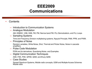
• Contents
– Introduction to Communication Systems
– Analogue Modulation
AM, DSBSC, VSB, SSB, FM, PM, Narrow band FM, PLL Demodulators, and FLL Loops
– Sampling Systems
Time and Frequency Division multiplexing systems, Nyquist Principle, PAM, PPM, and PWM.
– Principles of Noise
Random variables, White Noise, Shot, Thermal and Flicker Noise, Noise in cascade
amplifiers
– Pulse Code Modulation
PCM and its derivatives, Quantising Noise, and Examples
– Digital Communication Techniques
ASK, FSK, PSK, QPSK, QAM, and M-ary QAM.
– Case Studies
Spread Spectrum Systems, Mobile radio concepts, GSM and Multiple Access Schemes
Mobile radio
2. Recommended Text Books
• “An introduction to Analogue and Digital communication”, Haykin
(Wiley)
• “Communication Systems”, Carlson (McGraw & Hill)
• “Information, Transmission, Modulation and Noise”, Schwartz
(McGraw & Hill)
• “Analogue and Digital Communication Systems”, Raden (Prentice-
Hall)
• “Communication Systems”, Haykin (Wiley)
• “Electronic Communication Techniques”, Young (Merril-Publ)
3. Introduction to Modulation and
Demodulation
The purpose of a communication system is to transfer information from a source to a destination.
In practice, problems arise in baseband transmissions,
the major cases being:
• Noise in the system – external noise
and circuit noise reduces the
signal-to-noise (S/N) ratio at the receiver
(Rx) input and hence reduces the
quality of the output.
• Such a system is not able to fully utilise the available bandwidth,
for example telephone quality speech has a bandwidth ≃ 3kHz, a
co-axial cable has a bandwidth of 100's of Mhz.
• Radio systems operating at baseband frequencies are very difficult.
• Not easy to network.
4. Multiplexing
Multiplexing is a modulation method which improves channel bandwidth utilisation.
For example, a co-axial cable has a bandwidth of 100's of Mhz. Baseband speech is a o
5. 1) Frequency Division Multiplexing FDM
This allows several 'messages' to be translated from baseband, where they are all
in the same frequency band, to adjacent but non overlapping parts of the spectrum.
An example of FDM is broadcast radio (long wave LW, medium wave MW, etc.)
6. 2) Time Division Multiplexing TDM
TDM is another form of multiplexing based on sampling which is a modulation
technique. In TDM, samples of several analogue message symbols, each one
sampled in turn, are transmitted in a sequence, i.e. the samples occupy adjacent
time slots.
7. Radio Transmission
•Aerial dimensions are of the same order as the wavelength, , of the signal
(e.g. quarter wave /4, /2 dipoles).
is related to frequency by
f
c
=
λ where c is the velocity of an electromagnetic wave, and c =
3x10⁸ m/sec in free space.
For baseband speech, with a signal at 3kHz, (3x10³Hz) 3
8
3
3
x10
x10
=
λ = 105 metres or 100km.
• Aerials of this size are impractical although some transmissions at Very Low Frequency (VLF) for specialist
applications are made.
• A modulation process described as 'up-conversion' (similar to FDM) allows the baseband signal to be
translated to higher 'radio' frequencies.
• Generally 'low' radio frequencies 'bounce' off the ionosphere and travel long distances around the earth,
high radio frequencies penetrate the ionosphere and make space communications possible.
The ability to 'up convert' baseband signals has implications on aerial dimensions and design, long distance
terrestrial communications, space communications and satellite communications. Background 'radio' noise
is also an important factor to be considered.
• In a similar content, optical (fibre optic) communications is made possible by a modulation process in which
an optical light source is modulated by an information source.
8. Networks
• A baseband system which is essentially point-to-point
could be operated in a network. Some forms of access
control (multiplexing) would be desirable otherwise the
performance would be limited. Analogue
communications networks have been in existence for a
long time, for example speech radio networks for
ambulance, fire brigade, police authorities etc.
• For example, 'digital speech' communications, in which
the analogue speech signal is converted to a digital
signal via an analogue-to-digital converter give a form
more convenient for transmission and processing.
9. What is Modulation?
In modulation, a message signal, which contains the information is used to control the
parameters of a carrier signal, so as to impress the information onto the carrier.
The Messages
The message or modulating signal may be either:
analogue – denoted by m(t)
digital – denoted by d(t) – i.e. sequences of 1's and 0's
The message signal could also be a multilevel signal, rather than binary; this is not
considered further at this stage.
The Carrier
The carrier could be a 'sine wave' or a 'pulse train'.
Consider a 'sine wave' carrier:
c
c
c
c φ
+
t
ω
V
=
t
v cos
• If the message signal m(t) controls amplitude – gives AMPLITUDE MODULATION AM
• If the message signal m(t) controls frequency – gives FREQUENCY MODULATION FM
• If the message signal m(t) controls phase- gives PHASE MODULATION PM or M
10. • Considering now a digital message d(t):
If the message d(t) controls amplitude – gives AMPLITUDE SHIFT KEYING ASK.
As a special case it also gives a form of Phase Shift Keying (PSK) called PHASE REVERSAL
KEYING PRK.
• If the message d(t) controls frequency – gives FREQUENCY SHIFT KEYING FSK.
• If the message d(t) controls phase – gives PHASE SHIFT KEYING PSK.
• In this discussion, d(t) is a binary or 2 level signal representing 1's and 0's
• The types of modulation produced, i.e. ASK, FSK and PSK are sometimes described as binary
or 2 level, e.g. Binary FSK, BFSK, BPSK, etc. or 2 level FSK, 2FSK, 2PSK etc.
• Thus there are 3 main types of Digital Modulation:
ASK, FSK, PSK.
11. Multi-Level Message Signals
As has been noted, the message signal need not be either analogue (continuous) or
binary, 2 level. A message signal could be multi-level or m levels where each level
would represent a discrete pattern of 'information' bits. For example, m = 4 levels
12. • In general n bits per codeword will give 2n = m different patterns or levels.
• Such signals are often called m-ary (compare with binary).
• Thus, with m = 4 levels applied to:
Amplitude gives 4ASK or m-ary ASK
Frequency gives 4FSK or m-ary FSK
Phase gives 4PSK or m-ary PSK
4 level PSK is also called QPSK
(Quadrature Phase Shift Keying).
13. Consider Now A Pulse Train Carrier
p t E,0 t
p t 0, t T
p t
E
T
2E
T n 1
sinc
n
2
cos n
where
and
• The 3 parameters in the case are:
Pulse Amplitude E
Pulse width vt
Pulse position T
Hence:
• If m(t) controls E – gives PULSE AMPLITUDE MODULATION PAM
• If m(t) controls t - gives PULSE WIDTH MODULATION PWM
• If m(t) controls T - gives PULSE POSITION MODULATION PPM
In principle, a digital message d(t) could be applied but this will not be considered further.
26. Analogue Modulation – Amplitude
Modulation
vc(t) = Vc cos(ct), peak amplitude = Vc, carrier frequency c radians per second.
Since c = 2fc, frequency = fc Hz where fc = 1/T.
Consider a 'sine wave' carrier.
Amplitude Modulation AM
In AM, the modulating signal (the message signal) m(t) is 'impressed' on to the
amplitude of the carrier.
27. Message Signal m(t)
In general m(t) will be a band of signals, for example speech or video signals. A
notation or convention to show baseband signals for m(t) is shown below
28. Message Signal m(t)
In general m(t) will be band limited. Consider for example, speech via a microphone.
The envelope of the spectrum would be like:
29. Message Signal m(t)
In order to make the analysis and indeed the testing of AM systems easier, it is common to make
m(t) a test signal, i.e. a signal with a constant amplitude and frequency given by
m t Vm cos mt
30. Schematic Diagram for Amplitude
Modulation
VDC is a variable voltage, which can be set between 0 Volts and +V Volts. This
schematic diagram is very useful; from this all the important properties of AM and
various forms of AM may be derived.
31. Equations for AM
From the diagram where VDC is the DC voltage that can
be varied. The equation is in the form Amp cos ct and we may 'see' that the amplitude
is a function of m(t) and VDC. Expanding the equation we get:
t
ω
t
m
+
V
=
t
v c
DC
s cos
t
ω
t
m
+
t
ω
V
=
t
v c
c
DC
s cos
cos
32. Equations for AM
Now let m(t) = Vm cos mt, i.e. a 'test' signal,
t
ω
t
ω
V
+
t
ω
V
=
t
v c
m
m
c
DC
s cos
cos
cos
Using the trig identity
B
A
+
B
+
A
=
B
A
cos
cos
2
1
cos
cos
t
ω
ω
V
+
t
ω
+
ω
V
+
t
ω
V
=
t
v m
c
m
m
c
m
c
DC
s
cos
2
cos
2
cos
we have
Components: Carrier upper sideband USB lower sideband LSB
Amplitude: VDC Vm/2 Vm/2
Frequency: c c + m c – m
fc fc + fm fc + fm
This equation represents Double Amplitude Modulation – DSBAM
33. Spectrum and Waveforms
The following diagrams
represent the spectrum
of the input signals,
namely (VDC + m(t)),
with m(t) = Vm cos mt,
and the carrier cos ct
and corresponding
waveforms.
34. The above are input signals. The diagram below shows the spectrum and
corresponding waveform of the output signal, given by
vs t VDC cos ct
Vm
2
cos c m t
Vm
2
cos c m t
Spectrum and Waveforms
35. Double Sideband AM, DSBAM
The component at the output at the carrier frequency fc is shown as a broken line with
amplitude VDC to show that the amplitude depends on VDC. The structure of the
waveform will now be considered in a little more detail.
Waveforms
Consider again the diagram
VDC is a variable DC offset added to the message; m(t) = Vm cos mt
36. Double Sideband AM, DSBAM
This is multiplied by a carrier, cos ct. We effectively multiply (VDC + m(t)) waveform
by +1, -1, +1, -1, ...
The product gives the output signal vs t VDC m t cos ct
38. Modulation Depth
Consider again the equation
t
ω
t
ω
V
+
V
=
t
v c
m
m
DC
s cos
cos , which may be written as
The ratio is defined as the modulation depth, m, i.e. Modulation Depth
t
ω
t
ω
V
V
+
V
=
t
v c
m
DC
m
DC
s cos
cos
1
DC
m
V
V
=
m
From an oscilloscope display the modulation depth for Double Sideband AM may be
determined as follows:
DC
m
V
V
VDC
Vm
2Emin
2Emax
39. 2Emax = maximum peak-to-peak of waveform
2Emin = minimum peak-to-peak of waveform
Modulation Depth
min
max
min
max
E
+
E
E
E
=
m
2
2
2
2
This may be shown to equal
DC
m
V
V
as follows:
2Emax 2 VDC Vm
2Emin 2 VDC Vm
m
DC
m
DC
m
DC
m
DC
V
V
+
V
+
V
V
+
V
V
+
V
=
m
2
2
2
2
2
2
2
2
DC
m
V
V
4
4
DC
m
V
V
= =
Modulation Depth 2
40. Double Sideband Modulation 'Types'
There are 3 main types of DSB
• Double Sideband Amplitude Modulation, DSBAM – with carrier
• Double Sideband Diminished (Pilot) Carrier, DSB Dim C
• Double Sideband Suppressed Carrier, DSBSC
• The type of modulation is determined by the modulation depth,
which for a fixed m(t) depends on the DC offset, VDC. Note, when a
modulator is set up, VDC is fixed at a particular value. In the following
illustrations we will have a fixed message, Vm cos mt and vary VDC
to obtain different types of Double Sideband modulation.
43. Graphical Representation of Modulation
Depth and Modulation Types 3
Note then that VDC may be set to give
the modulation depth and modulation
type.
DSBAM VDC >> Vm, m 1
DSB Dim C 0 < VDC < Vm,
m > 1 (1 < m < )
DSBSC VDC = 0, m =
The spectrum for the 3 main types of
amplitude modulation are summarised
44. Bandwidth Requirement for DSBAM
In general, the message signal m(t) will not be a single 'sine' wave, but a band of frequencies
extending up to B Hz as shown
Remember – the 'shape' is used for convenience to distinguish low frequencies from high
frequencies in the baseband signal.
45. Bandwidth Requirement for DSBAM
Amplitude Modulation is a linear process, hence the principle of superposition
applies. The output spectrum may be found by considering each component cosine
wave in m(t) separately and summing at the output.
Note:
• Frequency inversion of the LSB
• the modulation process has effectively shifted or frequency translated the baseband
m(t) message signal to USB and LSB signals centred on the carrier frequency fc
• the USB is a frequency shifted replica of m(t)
• the LSB is a frequency inverted/shifted replica of m(t)
• both sidebands each contain the same message information, hence either the LSB or
USB could be removed (because they both contain the same information)
• the bandwidth of the DSB signal is 2B Hz, i.e. twice the highest frequency in the
baseband signal, m(t)
• The process of multiplying (or mixing) to give frequency translation (or up-conversion)
forms the basis of radio transmitters and frequency division multiplexing which will be
discussed later.
46. Power Considerations in DSBAM
2
m
V
8
2
2
2
2
m
m V
=
V
Remembering that Normalised Average Power = (VRMS)2 =
2
2
pk
V
we may tabulate for AM components as follows:
t
ω
ω
V
+
t
ω
+
ω
V
+
t
ω
V
=
t
v m
c
m
m
c
m
c
DC
s
cos
2
cos
2
cos
Component Carrier USB LSB
Amplitude pk VDC
Power
Power
8
2
2
2
2
m
m V
=
V
2
2
DC
V
2
m
V
2
2
DC
V
8
2
2
DC
V
m
8
2
2
DC
V
m
Total Power PT =
Carrier Power Pc
+ PUSB
+ PLSB
47. From this we may write two equivalent equations for the total power PT, in a DSBAM signal
4
2
8
8
2
2
2
2
2
2
m
DC
m
m
DC
T
V
+
V
=
V
+
V
+
V
=
P
The carrier power
2
2
DC
c
V
=
P
4
4
2
2
m
P
+
m
P
+
P
=
P c
c
c
T
2
1
2
m
+
P
=
P c
T
and
8
8
2
2
2
2
2
2
DC
DC
DC
T
V
m
+
V
m
+
V
=
P
or
i.e.
Either of these forms may be useful. Since both USB and LSB contain the same information a
useful ratio which shows the proportion of 'useful' power to total power is
2
2
2
2
2
4
2
1
4
m
+
m
=
m
+
P
m
P
=
P
P
c
c
T
USB
Power Considerations in DSBAM
48. Power Considerations in DSBAM
For DSBAM (m 1), allowing for m(t) with a dynamic range, the average value of m
may be assumed to be m = 0.3
0.0215
0.3
2
4
0.3
2
4 2
2
2
2
=
+
=
m
+
m
Hence, on average only about 2.15% of the total power transmitted may be regarded
as 'useful' power. ( 95.7% of the total power is in the carrier!)
Hence,
Even for a maximum modulation depth of m = 1 for DSBAM the ratio
6
1
2
4 2
2
=
m
+
m
i.e. only 1/6th of the total power is 'useful' power (with 2/3 of the total power in the
carrier).
49. Example
Suppose you have a portable (for example you carry it in your ' back pack') DSBAM transmitter
which needs to transmit an average power of 10 Watts in each sideband when modulation depth
m = 0.3. Assume that the transmitter is powered by a 12 Volt battery. The total power will be
4
4
2
2
m
P
+
m
P
+
P
=
P c
c
c
T
where
4
2
m
Pc = 10 Watts, i.e.
2
2
0.3
40
10
4
=
m
=
Pc
= 444.44 Watts
Hence, total power PT = 444.44 + 10 + 10 = 464.44 Watts.
Hence, battery current (assuming ideal transmitter) = Power / Volts =
12
464.44
i.e. a large and heavy 12 Volt battery.
amps!
Suppose we could remove one sideband and the carrier, power transmitted would be
10 Watts, i.e. 0.833 amps from a 12 Volt battery, which is more reasonable for a
portable radio transmitter.
50. Single Sideband Amplitude Modulation
One method to produce signal sideband (SSB) amplitude modulation is to produce
DSBAM, and pass the DSBAM signal through a band pass filter, usually called a
single sideband filter, which passes one of the sidebands as illustrated in the diagram
below.
The type of SSB may be SSBAM (with a 'large' carrier component), SSBDimC or
SSBSC depending on VDC at the input. A sequence of spectral diagrams are shown
on the next page.
52. Single Sideband Amplitude Modulation
Note that the bandwidth of the SSB signal B Hz is half of the DSB signal bandwidth.
Note also that an ideal SSB filter response is shown. In practice the filter will not be
ideal as illustrated.
As shown, with practical filters some part of the rejected sideband (the LSB in this
case) will be present in the SSB signal. A method which eases the problem is to
produce SSBSC from DSBSC and then add the carrier to the SSB signal.
54. Single Sideband Amplitude Modulation
with m(t) = Vm cos mt, we may write:
t
ω
ω
V
+
t
ω
+
ω
V
+
t
ω
V
=
t
v m
c
m
m
c
m
c
DC
s
cos
2
cos
2
cos
The SSB filter removes the LSB (say) and the output is
t
ω
+
ω
V
+
t
ω
V
=
t
v m
c
m
c
DC
s cos
2
cos
Again, note that the output may be
SSBAM, VDC large
SSBDimC, VDC small
SSBSC, VDC = 0
For SSBSC, output signal =
t
ω
+
ω
V
=
t
v m
c
m
s cos
2
55. Power in SSB
From previous discussion, the total power in the DSB signal is
2
1
2
m
+
P
=
P c
T
4
4
2
2
m
P
+
m
P
+
P
=
P c
c
c
T
Hence, if Pc and m are known, the carrier power and power in one sideband may be
determined. Alternatively, since SSB signal =
t
ω
+
ω
V
+
t
ω
V
=
t
v m
c
m
c
DC
s cos
2
cos
then the power in SSB signal (Normalised Average Power) is
8
2
2
2
2
2
2
2
2
m
DC
m
DC
SSB
V
+
V
=
V
+
V
=
P
Power in SSB signal =
8
2
2
2
m
DC V
+
V
= for DSBAM.
56. Demodulation of Amplitude Modulated
Signals
There are 2 main methods of AM Demodulation:
• Envelope or non-coherent Detection/Demodulation.
• Synchronised or coherent Demodulation.
57. This is obviously simple, low cost. But the AM input must be DSBAM with m << 1, i.e.
it does not demodulate DSBDimC, DSBSC or SSBxx.
An envelope detector for AM is shown below:
Envelope or Non-Coherent Detection
58. For large signal inputs, ( Volts) the diode is switched i.e. forward biased ON, reverse
biased OFF, and acts as a half wave rectifier. The 'RC' combination acts as a 'smoothing
circuit' and the output is m(t) plus 'distortion'.
If the modulation depth is > 1, the distortion below occurs
Large Signal Operation
59. Small Signal Operation – Square Law
Detector
For small AM signals (~ millivolts) demodulation depends on the diode square law
characteristic.
The diode characteristic is of the form i(t) = av + bv2 + cv3 + ..., where
t
ω
t
m
+
V
=
v c
DC cos i.e. DSBAM signal.
60. Small Signal Operation – Square Law
Detector
...
cos
cos
2
+
t
ω
t
m
+
V
b
+
t
ω
t
m
+
V
a c
DC
c
DC
...
cos
2
cos 2
2
2
+
t
ω
t
m
+
t
m
V
+
V
b
+
t
ω
t
am
+
aV c
DC
DC
c
DC
t
ω
+
t
bm
+
t
m
bV
+
bV
+
t
ω
t
am
+
aV c
DC
DC
c
DC 2
cos
2
1
2
1
2
cos
2
2
...
2
cos
2
2
2
2
2
cos
2
2
2
+
t
ω
V
b
+
t
bm
+
t
m
bV
+
bV
+
t
ω
t
am
+
aV c
DC
DC
DC
c
DC
t
m
bV
+
bV
+
aV DC
DC
DC
2
2
=
=
=
'LPF' removes components.
Signal out = i.e. the output contains m(t)
i.e.
61. Synchronous or Coherent Demodulation
A synchronous demodulator is shown below
This is relatively more complex and more expensive. The Local Oscillator (LO) must be
synchronised or coherent, i.e. at the same frequency and in phase with the carrier in the
AM input signal. This additional requirement adds to the complexity and the cost.
However, the AM input may be any form of AM, i.e. DSBAM, DSBDimC, DSBSC or
SSBAM, SSBDimC, SSBSC. (Note – this is a 'universal' AM demodulator and the
process is similar to correlation – the LPF is similar to an integrator).
62. Synchronous or Coherent Demodulation
If the AM input contains a small or large component at the carrier frequency, the LO
may be derived from the AM input as shown below.
63. Synchronous (Coherent) Local Oscillator
If we assume zero path delay between the modulator and demodulator, then the ideal
LO signal is cos(ct). Note – in general the will be a path delay, say , and the LO
would then be cos(c(t – ), i.e. the LO is synchronous with the carrier implicit in the
received signal. Hence for an ideal system with zero path delay
Analysing this for a DSBAM input =
t
ω
t
m
+
V c
DC cos
64. Synchronous (Coherent) Local Oscillator
VX = AM input x LO
t
ω
t
ω
t
m
+
V c
c
DC cos
cos
t
ω
t
m
+
V c
DC
2
cos
t
ω
+
t
m
+
V c
DC 2
cos
2
1
2
1
=
t
ω
t
m
+
t
m
+
t
ω
V
+
V
=
V c
c
DC
DC
x 2
cos
2
2
2
cos
2
2
We will now examine the signal spectra from 'modulator to Vx'
=
=
66. Synchronous (Coherent) Local Oscillator
Note – the AM input has been 'split into two' – 'half' has moved or shifted up to
t
ω
V
+
t
ω
t
m
f c
DC
c
c 2
cos
2
cos
2
2 and half shifted down to baseband,
2
DC
V
and
and
and
and
and
and
2
t
m
67. Synchronous (Coherent) Local Oscillator
The LPF with a cut-off frequency fc will pass only the baseband signal i.e.
2
2
t
m
+
V
=
V DC
out
In general the LO may have a frequency offset, , and/or a phase offset, , i.e.
The AM input is essentially either:
• DSB (DSBAM, DSBDimC, DSBSC)
• SSB (SSBAM, SSBDimC, SSBSC)
68. 1. Double Sideband (DSB) AM Inputs
The equation for DSB is
t
ω
t
m
+
V c
DC cos
diminished carrier or suppressed carrier to be set.
where VDC allows full carrier (DSBAM),
Hence, Vx = AM Input x LO
Δφ
+
t
Δω
+
ω
.
t
ω
t
m
+
V
=
V c
c
DC
x cos
cos
Since
B
A
+
B
+
A
=
B
A
cos
cos
2
1
cos
cos
t
ω
Δφ
+
t
Δω
+
ω
+
Δφ
+
t
Δω
+
ω
+
ω
t
m
+
V
=
V c
c
c
c
DC
x
cos
cos
2
Δφ
+
Δωt
+
Δφ
+
t
Δω
+
ω
t
m
+
V
=
V c
DC
x cos
2
cos
2
2
Δφ
+
Δωt
t
m
+
Δφ
+
t
Δω
+
ω
t
m
+
Δφ
+
Δωt
V
+
Δφ
+
t
Δω
+
ω
V
=
V
c
DC
c
DC
x
cos
2
2
cos
2
cos
2
2
cos
2
69. 1. Double Sideband (DSB) AM Inputs
The LPF with a cut-off frequency fc Hz will remove the components at 2c (i.e.
components above c) and hence
φ
+
ωt
t
m
+
φ
+
t
V
=
V DC
out
cos
2
)
cos(
2
Obviously, if 0
=
Δω and 0
Δφ we have, as previously
2
2
t
m
+
V
=
V DC
out
Consider now if is equivalent to a few Hz offset from the ideal LO. We may then
say
Δωt
t
m
+
Δωt
V
=
V DC
out cos
2
cos
2
The output, if speech and processed by the human brain may be intelligible, but
would include a low frequency 'buzz' at , and the message amplitude would
fluctuate. The requirement = 0 is necessary for DSBAM.
70. 1. Double Sideband (DSB) AM Inputs
Consider now if is equivalent to a few Hz offset from the ideal LO. We may then
say
Δωt
t
m
+
Δωt
V
=
V DC
out cos
2
cos
2
The output, if speech and processed by the human brain may be intelligible, but would
include a low frequency 'buzz' at , and the message amplitude would fluctuate. The
requirement = 0 is necessary for DSBAM.
Consider now that = 0 but 0, i.e. the frequency is correct at c but there is a
phase offset. Now we have
Δφ
t
m
+
Δφ
V
=
V DC
out cos
2
cos
2
'cos()' causes fading (i.e. amplitude reduction) of the output.
71. 1. Double Sideband (DSB) AM Inputs
2
π
=
Δφ
The 'VDC' component is not important, but consider for m(t),
• if
2
π
=
Δφ 0
2
cos =
π
(900), i.e.
0
2
cos
2
=
π
t
m
=
Vout
(1800), 1
cos
=
π
• if
t
m
=
π
t
m
=
Vout
cos
2
i.e.
The phase inversion if = may not be a problem for speech or music, but it may be
a problem if this type of modulator is used to demodulate PRK
However, the major problem is that as increases towards
2
π
the signal strength
output gets weaker (fades) and at
2
π
the output is zero
72. 1. Double Sideband (DSB) AM Inputs
If the phase offset varies with time, then the signal fades in and out. The variation of
amplitude of the output, with phase offset is illustrated below
Thus the requirement for = 0 and = 0 is a 'strong' requirement for DSB amplitude
modulation.
73. 2. Single Sideband (SSB) AM Input
The equation for SSB with a carrier depending on VDC is
t
ω
+
ω
V
+
t
ω
V m
c
m
c
DC cos
2
cos
i.e. assuming
t
ω
V
=
t
m m
mcos
Hence
Δφ
+
t
+
ω
t
ω
+
ω
V
+
t
ω
V
=
V c
m
c
m
c
DC
x
cos
cos
2
cos
Δφ
t
Δω
ω
V
+
Δφ
+
t
Δω
+
ω
+
ω
V
+
Δφ
+
Δωt
V
+
Δφ
+
t
Δω
+
ω
V
m
m
m
c
m
DC
c
DC
cos
4
2
cos
4
cos
2
2
cos
2
=
74. 2. Single Sideband (SSB) AM Input
The LPF removes the 2c components and hence
Δφ
t
Δω
ω
V
+
Δφ
+
Δωt
V
m
m
DC
cos
4
cos
2
Note, if = 0 and = 0,
t
ω
V
+
V
m
m
DC
cos
4
2
t
ω
V
=
t
m m
mcos
,i.e. has been
recovered.
Consider first that 0, e.g. an offset of say 50Hz. Then
t
Δω
ω
V
+
Δωt
V
=
V m
m
DC
out
cos
4
cos
2
If m(t) is a signal at say 1kHz, the output contains a signal a 50Hz, depending on VDC
and the 1kHz signal is shifted to 1000Hz - 50Hz = 950Hz.
75. 2. Single Sideband (SSB) AM Input
The spectrum for Vout with offset is shown
Hence, the effect of the offset is to shift the baseband output, up or down, by .
For speech, this shift is not serious (for example if we receive a 'whistle' at 1kHz and
the offset is 50Hz, you hear the whistle at 950Hz ( = +ve) which is not very
noticeable. Hence, small frequency offsets in SSB for speech may be tolerated.
Consider now that = 0, = 0, then
Δφ
t
ω
V
+
Δφ
V
=
V m
m
DC
out
cos
4
cos
2
76. 2. Single Sideband (SSB) AM Input
• This indicates a fading VDC and a phase shift in the
output. If the variation in with time is relatively slow,
thus phase shift variation of the output is not serious for
speech.
• Hence, for SSB small frequency and phase variations in
the LO are tolerable. The requirement for a coherent LO
is not as a stringent as for DSB. For this reason, SSBSC
(suppressed carrier) is widely used since the receiver is
relatively more simple than for DSB and power and
bandwidth requirements are reduced.
77. Comments
• In terms of 'evolution', early radio schemes and radio on long wave (LW)
and medium wave (MW) to this day use DSBAM with m < 1. The reason for
this was the reduced complexity and cost of 'millions' of receivers compared
to the extra cost and power requirements of a few large LW/MW
transmitters for broadcast radio, i.e. simple envelope detectors only are
required.
• Nowadays, with modern integrated circuits, the cost and complexity of
synchronous demodulators is much reduced especially compared to the
additional features such as synthesised LO, display, FM etc. available in
modern receivers.
Amplitude Modulation forms the basis for:
• Digital Modulation – Amplitude Shift Keying ASK
• Digital Modulation – Phase Reversal Keying PRK
• Multiplexing – Frequency Division Multiplexing FDM
• Up conversion – Radio transmitters
• Down conversion – Radio receivers