Downloaded 28 times


![An 8-Bit Multiplier
7
References
[1]http://www2.elo.utfsm.cl/~lsb/elo211/aplicaciones/katz/chapter5/chapter05.doc6.ht
ml.
[2]http://www.datasheetarchive.com/5%20bit%20binary%20multiplier%20using%20a
dders-datasheet.html.
[3] http://lap2.epfl.ch/courses/archord1/labs/A_8bit_Sequential_Multiplier.pdf.
[4] https://wiki.engr.illinois.edu/download/attachments/84770821/09-
AdditionMultiplication.pdf?version=1&modificationDate=1254112213000.](https://image.slidesharecdn.com/an8bitmultiplier-141129093859-conversion-gate01/85/An-8-bit_multiplier-7-320.jpg)


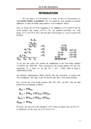
This document describes the design of an 8-bit multiplier circuit. It uses 4-bit multipliers as building blocks, along with adders and carry look-ahead units. The 8-bit numbers are broken into 4-bit groups, and the partial products of each group are generated using 4-bit multipliers. Adders are then used to sum the slices of the partial products to obtain the final 16-bit product. The implementation requires four 4-bit multipliers, four 4-bit adders, three arithmetic logic units, and an optional carry look-ahead unit, for a total of 12 packages. While this design works, the document notes a direct 8-bit multiplier would have been simpler if 8-bit