Download to read offline
![A RADIX-8 MULTIPLIER UNIT DESIGN
FOR SPECIFIC PURPOSE
J.A. Hidalgo, V. Moreno-Vergara, O. Oballe, A. Daza, M.J. Martín-Vázquez, A.Gago
Dept. de Electrónica, E.T.S.I. Industriales
Plaza El Ejido S/N, 29013 Málaga
Tel.&Fax: +34 952132783
E-mail: jahidalgo@uma.es
Abstract In this paper, a 21×21-bit, 2s-
complement binary numbers, radix-8 multiplier unit
design for specific purpose is presented. Specific
purpose means that the multiplicand belongs to a
previously known set of numbers which are stored
in a memory, so it can be used to make a
modification in the radix-8 multiplication
algorithm. We can modify the previous adder so
that it runs faster. A full-custom layout-level design
and electrical simulation of the multiplier unit has
been done. Results have been compared to what we
could get applying a more conventional radix-4
multiplier architecture.
I. Introduction
Multipliers play an important part in
today’s digital signal processing (DSP) systems.
Examples of their use occur in implementations of
recursive and transverse filters, discrete Fourier
transforms, correlation, range measurement … and
in most of these cases it is enough with a multiplier
unit design for specific purpose. Advances in
technology have permitted many researchers to
design multipliers which offer both high-speed and
regularity of layout, thereby making them suitable
for VLSI implementation.
In any multiplication algorithm, the
operation is decomposed in a partial product
summation. Each partial product represents a
multiple of the multiplicand to be added to the final
result. Nowadays almost all high-speed multipliers
apply a radix-4 recoding multiplication algorithm.
Radix-8 recoding allows a time gain in the partial
products summation but it is not applied because
we have to generate one of the multiples of the
multiplicand (an odd multiple) using a high-speed
adder (the previous adder). This requirement leads
to a significant delay penalty (about 10-20%),
compared to a radix-4 architecture (where the
partial products may be generated by simple
shifting and/or complementing) [1].
However, our multiplier is designed for
specific purpose and this can be used to modify the
previous adder. In this way, the generation of the
odd multiple is speeded up, thereby decreasing the
disadvantage in relation to the radix-4 architecture.
Another point that makes interesting the use of a
radix-8 recoding is the less number of transistors
resulting in a reduced power dissipation and active
area size, compared to a radix-4 architecture.
Generally, the multiplication algorithm is
very similar to the operation made by hand. Thus,
in a radix-2 algorithm, first we make a series of
products between the multiplicand, Y, and every bit
of the multiplier, X, generating in this way a set of
words called partial products. Next, all the partial
products are added. We use some kind of redundant
arithmetic to get the additions as fast as possible.
Usually the speed is increased with a Wallace
reduction tree [2]. In the conventional Wallace tree,
multi-input partial product bits, at the same bit
position, are consecutively compressed to a final
sum and carry signal pair by using a series of
single-bit full adders (also called 3-2 compressors).
At the output, we have two words (sum and carry)
which have to be added as fast as possible by a
carry-propagate adder (CPA). The Wallace tree
structure is a version of the carry-save adders
(CSA).
Radix-4 multiplication obtains an
improvement in the multiplication algorithm due to
the less number of partial products entering the
Wallace tree to be reduced. This can be achieved by
the application of the multiplier recoding, changing](https://image.slidesharecdn.com/radix8-151205055932-lva1-app6891/85/Radix8-1-320.jpg)
![A RADIX-8 MULTIPLIER UNIT DESIGN
FOR SPECIFIC PURPOSE
J.A. Hidalgo, V. Moreno-Vergara, O. Oballe, A. Daza, M.J. Martín-Vázquez, A.Gago
Dept. de Electrónica, E.T.S.I. Industriales
Plaza El Ejido S/N, 29013 Málaga
Tel.&Fax: +34 952132783
E-mail: jahidalgo@uma.es
Abstract In this paper, a 21×21-bit, 2s-
complement binary numbers, radix-8 multiplier unit
design for specific purpose is presented. Specific
purpose means that the multiplicand belongs to a
previously known set of numbers which are stored
in a memory, so it can be used to make a
modification in the radix-8 multiplication
algorithm. We can modify the previous adder so
that it runs faster. A full-custom layout-level design
and electrical simulation of the multiplier unit has
been done. Results have been compared to what we
could get applying a more conventional radix-4
multiplier architecture.
I. Introduction
Multipliers play an important part in
today’s digital signal processing (DSP) systems.
Examples of their use occur in implementations of
recursive and transverse filters, discrete Fourier
transforms, correlation, range measurement … and
in most of these cases it is enough with a multiplier
unit design for specific purpose. Advances in
technology have permitted many researchers to
design multipliers which offer both high-speed and
regularity of layout, thereby making them suitable
for VLSI implementation.
In any multiplication algorithm, the
operation is decomposed in a partial product
summation. Each partial product represents a
multiple of the multiplicand to be added to the final
result. Nowadays almost all high-speed multipliers
apply a radix-4 recoding multiplication algorithm.
Radix-8 recoding allows a time gain in the partial
products summation but it is not applied because
we have to generate one of the multiples of the
multiplicand (an odd multiple) using a high-speed
adder (the previous adder). This requirement leads
to a significant delay penalty (about 10-20%),
compared to a radix-4 architecture (where the
partial products may be generated by simple
shifting and/or complementing) [1].
However, our multiplier is designed for
specific purpose and this can be used to modify the
previous adder. In this way, the generation of the
odd multiple is speeded up, thereby decreasing the
disadvantage in relation to the radix-4 architecture.
Another point that makes interesting the use of a
radix-8 recoding is the less number of transistors
resulting in a reduced power dissipation and active
area size, compared to a radix-4 architecture.
Generally, the multiplication algorithm is
very similar to the operation made by hand. Thus,
in a radix-2 algorithm, first we make a series of
products between the multiplicand, Y, and every bit
of the multiplier, X, generating in this way a set of
words called partial products. Next, all the partial
products are added. We use some kind of redundant
arithmetic to get the additions as fast as possible.
Usually the speed is increased with a Wallace
reduction tree [2]. In the conventional Wallace tree,
multi-input partial product bits, at the same bit
position, are consecutively compressed to a final
sum and carry signal pair by using a series of
single-bit full adders (also called 3-2 compressors).
At the output, we have two words (sum and carry)
which have to be added as fast as possible by a
carry-propagate adder (CPA). The Wallace tree
structure is a version of the carry-save adders
(CSA).
Radix-4 multiplication obtains an
improvement in the multiplication algorithm due to
the less number of partial products entering the
Wallace tree to be reduced. This can be achieved by
the application of the multiplier recoding, changing](https://image.slidesharecdn.com/radix8-151205055932-lva1-app6891/75/Radix8-1-2048.jpg)
![from a 2s-complement format to a signed-digit
representation from the set {0, ±1, ±2}.
We will also reduce the number of partial
products using a higher radix in the multiplier
recoding, thereby obtaining a simpler Wallace tree.
This implies a less delay through the compressors
and a smaller active area size. In the other hand, we
will need some multiples of the multiplicand which
are not immediately available, but are generated by
a previous adder, making worse the overall
multiplication time.
In the next section will be described the
radix-4 and radix-8 recoding of binary numbers,
which is the basis of our multiplication algorithm.
We will also explain the modification of the
previous adder. Later in section 3 is briefly
explained the design of the components of our
21×21 radix-8 multiplier. In section 4 we comment
the implementation and simulation results,
comparing our multiplier to its equivalent radix-4
and generic radix-8 architectures. Section 5 will
appear as a conclusion of our design.
II. Radix-4 and radix-8 multiplication
Recoding of binary numbers was first
hinted at by Booth [3] four decades ago. MacSorley
[4] proposed a modification of Booth’s algorithm a
decade after. The modified Booth’s algorithm
(radix-4 recoding) starts by appending a zero to the
right of x0 (multiplier LSB). Triplets are taken
beginning at position x –1 and continuing to the
MSB with one bit overlapping between adjacent
triplets. If the number of bits in X (excluding x –1) is
odd, the sign (MSB) is extended one position to
ensure that the last triplet contains 3 bits. In every
step we will get a signed digit that will multiply the
multiplicand to generate a partial product entering
the Wallace reduction tree. The meaning of each
triplet can be seen in figure 1:
xi+2 xi+1 xi Partial product
0 0 0 0Y
0 0 1 +1Y
0 1 0 +1Y
0 1 1 +2Y
1 0 0 -2Y
1 0 1 -1Y
1 1 0 -1Y
1 1 1 0Y
x x x x x x x x 0
D3 D1
D0D2
Fig. 1: Radix-4 recoding.
This recoding scheme applied to a parallel
multiplier halves the number of partial products so
the multiplication time and the hardware
requirements decrease. This gain is possible at the
expense of somewhat more complex operations in
every step. It should be noted, however, that the
required multiples of Y {0, ±Y, ±2Y} are available
by merely shifting Y to the left.
Although the algorithms and operations
specified above seem rather arbitrary at the first
sight, they are based on meaningful number
systems [5]. If one focuses on what modifications
are being done to X, then one may arrive at a
different representation for the 2s-complement
number X as shown in figure 2:
Fig. 2: Signed-digit representation.
where digits Di are one of {-2, -1, 0, 1, 2} found in
the table of figure 1, based on the value of triplets
in the form (xi+2 xi+1 xi). Here we have a signed-
digit representation of X in radix-4.
Signed-digit number representation allows
redundancy to exist. Thanks to this we can make a
parallel recodification, that is, all triplets are
recoded at the same time, and the value of each
triplet is independent from the adjacent triplets.
Radix-8 recoding applies the same
algorithm as radix-4, but now we take quartets of
bits instead of triplets. Each quartet is codified as a
signed-digit using the table 1:
Table 1: Radix-8 recoding.
Quartet value Signed-digit value
0000 0
0001 +1
0010 +1
0011 +2
0100 +2
0101 +3
0110 +3
0111 +4
1000 -4
1001 -3
1010 -3
1011 -2
1100 -2
1101 -1
1110 -1
1111 0
Here we have an odd multiple of the multiplicand,
3Y, which is not immediately available. To
X Di
i
i
n
= ⋅
=
−
∑ 4
0
2
1
x x x x x x x x 0
D3 D1
D0D2](https://image.slidesharecdn.com/radix8-151205055932-lva1-app6891/85/Radix8-2-320.jpg)
![generate it we need to perform this previous add:
2Y+Y=3Y.
But we are designing a multiplier for
specific purpose and thereby the multiplicand
belongs to a previously known set of numbers
which are stored in a memory chip. We have tried
to take advantage of this fact, to ease the bottleneck
of the radix-8 architecture, that is, the generation of
3Y. In this manner we try to attain a better overall
multiplication time, or at least comparable to the
time we could obtain using a radix-4 architecture
(with the additional advantage of using a less
number of transistors).
To generate 3Y with 21-bit words we only
have to add 2Y+Y, that is, to add the number with
the same number shifted one position to the left,
getting in this way a new 23-bit word, as shown in
figure 3:
Fig. 3: 21-bit previous add.
In fact, only a 21-bit adder is needed to generate the
bit positions from z1 to z21. Bits z0 and z22 are
directly known because z0=y0 and z22=y20 (sign bit
of the 2s-complement number; 3Y and Y have the
same sign).
If in the memory from where we take the
numbers justtwo additional bits are stored together
with each value of the set of numbers, we can
decompose the previous add in three shorter adds
that can be done in parallel. In this way, the delay is
the same of a 7-bit adder:
Bits which are going to be stored are the two
intermediate carry signals c8 and c15. Before each
word of the set of numbers is stored in the memory,
the value of its intermediate carries has to be
obtained and stored beside it. In this way, they are
immediately available when it is required to
perform the previous add to get the multiple 3Y of
one of the numbers that belongs to the set.
The increment in memory requirements is
relatively small (9.5%, 23 bits instead of 21 for
every word), and the gain in time is obvious
because we substitute a 21-bit adder by three 7-bit
adders which can operate in parallel. In order to get
the minimum delay in the previous adder we use
high-speed adders. The adders that best fit our
needs are the carry and sum select adders (CSSA)
with an estimated delay of n [6] where n is the
word length. So reducing the word length to one
third, the diminishing of the previous add delay will
be 42% approximately. Although this reduction, the
previous add delay will keep on being dominant
compared to the recodification time which is the
only operation that can be done in parallel with the
previous add.
III. Multiplier unit design
The multiplication of two binary numbers,
21-bit length, 2s-complement and using the
algorithm with radix-8 recoding of the multiplier
presents the following features:
a) Radix-8 recoding of the multiplier implies a
reduction in the number of digits to 7:
s x x x x x x x x x x x x x x x x x x x x 0
D3 D1
D0D2
D5
D4D6
Fig. 5: Multiplier recoding.
b) The partial products multiplexer must
choose one out of nine possibilities depending on
the value of the corresponding signed-digit, as
shown in figure 6:
y y y y y y y Y
y y y y y y y y
z z z z z z z z z
20 19 18 3 2 1 0
20 20 19 4 3 2 1 0
22 21 20 19 4 3 2 1 0
0.....
.....
.....
2
Y
⋅
y y y y y y y
y y y y y y y
z z z z z z z
6 5 4 3 2 1 0
7 6 5 4 3 2 1
7 6 5 4 3 2 1
y c13 8
y y y y y y
y y y y y y y
z z z z z z z
12 11 10 9 8 7
14 13 12 11 10 9 8
14 13 12 11 10 9 8
←
y y y y y y y
y y y y y y y
z z z z z z z
20 19 18 17 16 15 14
20 20 19 18 17 16 15
21 20 19 18 17 16 15
← c15
Fig. 4: Modified previous add.](https://image.slidesharecdn.com/radix8-151205055932-lva1-app6891/85/Radix8-3-320.jpg)
![Fig. 6: Partial products multiplexer.
c) The partial product length is two bits longer
than the multiplicand length, giving 23-bit length
partial products.
d) The number of partial products entering the
Wallace tree structure is 8: 7 coming from the
multiplier recoded digits plus another partial
product due to the compensation bits of the 2s-
complement multiplication algorithm which cannot
be included in any of the other 7 words.
e) The best structure for the reduction of 8
partial products applies only 4-2 compressors [7]
(instead of the conventional full adders) which can
be seen in this figure:
Fig. 7: 4-2 compressors.
The Wallace tree has the following scheme:
with an equivalent delay of 6 logic gates.
f) The previous and the final add must be done
as fast as possible, so they are implemented with
carry and sum select adders (CSSA).
In order to have a better understanding of
the multiplier design we are going to show an
example following the radix-8 recoding algorithm.
Consider the multiplication of these 2s-complement
binary numbers:
Multiplicand: 111100010010110111001
Multiplier: 100011010100110100111
The multiplier recoding has the result shown here
(following table 1):
1 0 0 0 1 1 0 1 0 1 0 0 1 1 0 1 0 0 1 1 1 0
-3 -3
-1-1
3
3-4
The generation of three times the multiplicand
gives:
1 1 1 1 0 0 0 ← 0 1 0 0 1 0 1 1 ← 1 0 1 1 1 0 0 1 0
+
1 1 1 1 1 0 0 0 1 0 0 1 0 1 1 0 1 1 1 0 0 1
1 1 1 1 0 1 0 0 1 1 1 0 0 0 1 0 0 1 0 1 0 1 1
The partial products array and its summation, which
gives the multiplication result, is shown in figure 9.
In the array, some bits are encircled (fixed 1’s) and
they avoid the partial products sign extension.
Some other bits are squared and they will be 1’s
when the corresponding partial product has to be
complemented (if recodification gives a negative
digit). The leading four partial products will enter
the first block of 4-2 compressors while the other
three partial products plus the compensation bits
will enter the second block of 4-2 compressors, still
in the first compression level. Moreover, the final
adder has been decomposed in three adders with
lengths 3, 6 and 31 bits. The 31-bit adder is the
proper final adder while the 3 and the 6-bit adders
are used to advance bits of the final result without
passing through all the compression blocks in the
Wallace tree.
a1
a0
a1
a2
cout
0
1
a3
cin
cin
s
c0
1
a3
a2
From previous
adder
To Wallace tree
0
1
-1
2
-2
3
-3
4
-4
yi
yi
yi-1
yi-1
3⋅yi
3⋅yi
yi-2
yi-2
Di (from recodification)
PP1 PP2 PP3 PP4
4-2 4-2
Final adder, CPA
4-2
PP5 PP6 PP7 PP8
Fig. 8: Wallace reduction tree.](https://image.slidesharecdn.com/radix8-151205055932-lva1-app6891/85/Radix8-4-320.jpg)
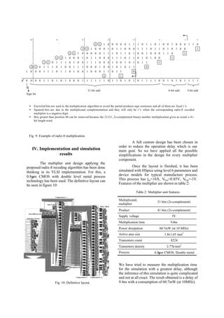
![To compare the operation time of a radix-4
and a radix-8 architecture we can follow figure 11:
Fig. 11: Time diagram.
These diagrams are not quantitative; they just
pretend to give a qualitative idea of the multiplier
components delay. These delays are supposed to be
the same for both architectures in the recodification,
multiplexation, one level of the Wallace tree and
the final adder. This is strictly true for the final
adder only.
It can be concluded that the radix-8
architecture will be faster than the radix-4 if the
previous add delay is smaller than the delay through
a radix-4 recodification and one 3-2 compressors
stage. As we don’t have simulation results for a
radix-4 and a generic radix-8 architectures, their
operation times have been estimated under our
design style. So we can make the next time
diagram:
Fig. 12: Radix-4/radix-8 comparison.
As said before, generic radix-8 is slower than radix-
4, what it is confirmed with these results. However,
our radix-8 multiplier for specific purpose, reducing
the previous add time in more than 1ns, has also
obtained a time advantage compared to a radix-4
architecture. This has been possible just storing two
additional bits together with each value of the
multiplicand within the set of numbers stored in the
memory.
V. Conclusion
It has been performed the design,
implementation and simulation of a 21×21-bit,
radix-8, multiplier unit for specific purpose. The
number of transistors is 8224 with an active area
size of 2.97 mm2
. The measured multiplication time
is 9.4 ns and the power dissipation is 60.7 mW at
the frequency of 10 MHz.
It has been proved that it can be useful to
apply a radix-8 architecture in high-speed
multipliers for specific purpose because of the gain
in time and number of transistors compared to the
conventional radix-4 recoding architecture. This
can be achieved with a slight modification in the
previous adder. To do the modification is needed to
store two additional bits (intermediate carries) for
each word in the set of numbers. Memory needs are
increased in a 9.5% while time decrease in the
previous adder can be estimated in a 42%. Due to
this, the overall multiplication time can be reduced
with our radix-8 architecture for specific purpose.
References
[1] B. Millar, P.E. Madrid and E.E. Swartzlander, Jr.,
“A fast hybrid multiplier combining Booth and
Wallace/Dadda algorithms,” Proc. of the 35th
IEEE
Midwest Symposium on Circuits and Systems, pp.
158-165, Aug. 1992.
[2] C.S. Wallace, “A suggestion for fast multipliers,”
IEEE Trans. Electron. Comput., Feb. 1964.
[3] A.D. Booth, “A signed binary multiplication
technique,” Quarterly J. Mechan. Appl. Math., vol
IV. Part 2, 1951.
[4] O.L. MacSorley, “High speed arithmetic in binary
computers,” Proc. IRE, Jan. 1961.
[5] H. Sam y A. Gupta, “A generalized multibit
recoding of two’s complement binary numbers and
its proof with application in multiplier
implementations,” IEEE Trans. Comput., Aug. 1990,
pp.1006-1015.
[6] T.G. Noll, “Carry-save architectures for high-speed
digital signal processing,” Journal of VLSI Signal
Processing, 1991, pp. 121-140.
[7] M.R. Santoro, “A pipelined 64×64 iterative array
multiplier,” Proc. Dig. Tech. Papers Int. Solid- State
Circ. Conf., Feb. 1988.
Recodification
Multiplexation
Wallace tree
(3 levels)
Final add
Recod.
Multiplexation
Wallace tree
(2 levels)
Final add
Previous
add
SPECIFIC RADIX-8RADIX-4
Recod.
Multiplexation
Wallacetree
(2 levels)
Final add
Previous
add
GENERIC RADIX-8
0 1 2 3 4
Generic
Radix 8
Specific
Radix-8
Radix-4
Time (ns)
3,4 ns
2,3 ns
3 ns
Previous add
Previous add
3-2 compressorRecod.](https://image.slidesharecdn.com/radix8-151205055932-lva1-app6891/85/Radix8-6-320.jpg)

This document describes the design of a 21x21-bit radix-8 multiplier unit for specific purposes. It presents a modification to the radix-8 multiplication algorithm to speed up the generation of the odd multiple (3Y) of the multiplicand by taking advantage of the fact that the multiplicand belongs to a known set of numbers stored in memory. This allows decomposing the previous adder into three 7-bit adders that can operate in parallel, reducing the delay by about 42% compared to a standard 21-bit adder. The design includes a radix-8 recoding of the multiplier, multiplexers to generate the partial products, a Wallace tree using 4-2 compressors to reduce the partial