Downloaded 493 times
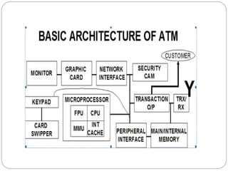
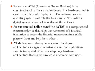
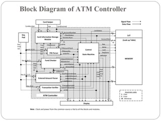
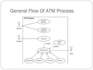
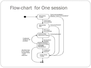
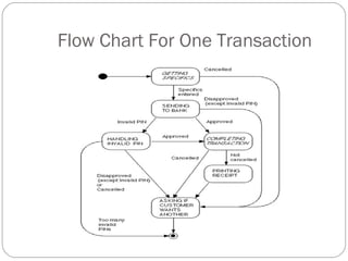
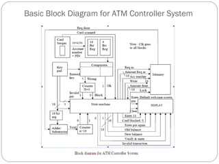
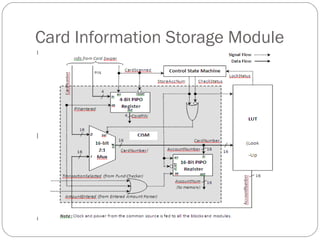
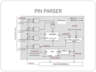
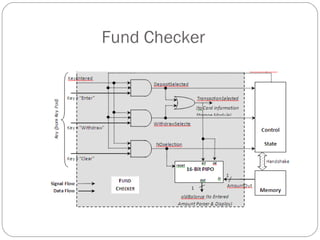
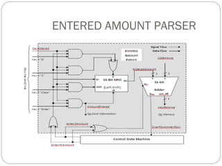
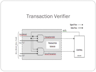
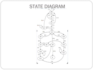
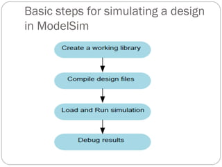
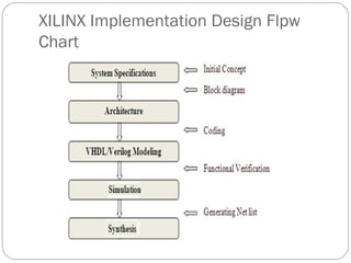
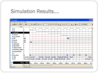
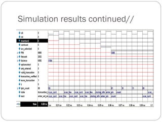
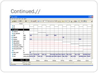
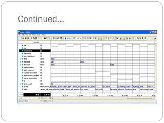


This document presents a mini project on designing an automated teller machine (ATM) controller. The objectives are to review literature on ATM controllers, design the architecture specifications, develop a Verilog model, and verify functionality through behavioral simulation and FPGA synthesis. Key components of the ATM controller include a card swiper, keypad, display, memory modules, and a state machine controlled transaction verification process. The controller will be modeled in Verilog and simulated using Modelsim, with the intended functionality verified through test cases.