INTRODUCTION
A binary adderis a digital circuit used in computers and digital systems to
perform the addition of binary numbers. There are different types of binary
adders, each suited for specific tasks.
HALF ADDER:
A half adder is a combinational logic circuit that performs binary addition of
two single-bit inputs, A and B, producing two outputs: SUM and CARRY.
FULLADDER:
Full Adder is a combinational circuit that adds three inputs and produces two
outputs. The first two inputs are A and B and the third input is an input carry
as C-IN. The output carry is designated as C-OUT and the normal output is
designated as S which is SUM.
4.
INTRODUCTION
4 BIT BINARYADDER:
A 4-bit full adder is a digital circuit that performs the addition of two 4-bit binary
numbers, along with a carry input from a previous addition. It outputs a 4-bit sum and a
carry output.
A full adder adds binary numbers and accounts for values carried in as well as out. The
four basic addition operations are 0 + 0 = 0, 1 + 0 = 1, 0 + 1 = 1 and 1 + 1 = 10. In the
first three operations, each binary addition gives sum as one bit, i.e., either 0 or 1. But
the fourth addition operation gives a sum that consists of two binary digits. In such result
of the addition, lower significant bit is called as the sum bit, whereas the higher
significant bit is called as the carry bit.
5.
MATERIALS USED
IC (7483-4 Bit Adder)
LEDs
7805 voltage regulator IC (5V)
Resistors
DIP switches
Jumper wires
Power Source: 9V Battery
Breadboard
6.
OBJECTIVE
• To Fabricateand understand the working of 4 Bit
Binary Adder using suitable IC and components.
• To Display the output of Addition for different
combinations of 44 Bit binary numbers using LEDs
• To assemble the circuit on the breadboard using
other components
• To learn about designing circuit & making it by hand.
DC POWER SUPPLYCIRCUIT
First we are using a 9V Battery. The battery supply is
fed to the input of the 7805 Voltage regulator. 7805
regulates the 9V DC to 5V and at the output of 7805 IC,
we get constant 5V DC Output.
9.
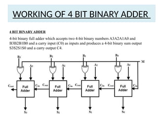
WORKING OF 4BIT BINARY ADDER
4 BIT BINARY ADDER
4-bit binary full adder which accepts two 4-bit binary numbers A3A2A1A0 and
B3B2B1B0 and a carry input (C0) as inputs and produces a 4-bit binary sum output
S3S2S1S0 and a carry output C4.
10.
WORKING OF 4BIT BINARY ADDER
Logic circuit diagram
11.
WORKING OF 4BIT BINARY ADDER
Truth Table of 4 Bit Binary Adder:
12.
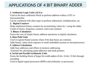
APPLICATIONS OF 4BIT BINARY ADDER
1. Arithmetic Logic Units (ALUs)
Used as the basic arithmetic block to perform addition within a CPU or
microcontroller.
Can be combined with other logic to perform subtraction, multiplication, etc.
2. Digital Counters
Helps implement binary counters by incrementing values by 1 using the adder.
Useful in timers, frequency counters, and event counters.
3. Binary Calculators
Forms the core of simple binary addition operations in digital calculators.
4. Data Path Units
Used in register-based systems where 4-bit data buses are common.
Adds binary values from registers in small embedded systems or microprocessors.
5. Address Calculation
Adds base addresses and offsets in memory addressing.
Essential for calculating jump addresses and stack pointers.
6. Serial and Parallel Arithmetic Units
Forms the building block of larger bit-width adders (8-bit, 16-bit, 32-bit) through
cascading.
Used in digital signal processors (DSPs) and arithmetic co-processors.
CONCLUSION
Building a 4BIT BINARY ADDER is a rewarding project that
combines learning and practical application.
Enhances understanding of IC7483 and its applications in
fabricating 4 Bit Binary Adder circuit.
Encourages hands-on learning and experimentation in
electronics.


![Binary-Adders-A-Deep-Dive b in dld[1].pptx](https://cdn.slidesharecdn.com/ss_thumbnails/binary-adders-a-deep-dive1-241206171332-4ce6a9eb-thumbnail.jpg?width=640&height=640&fit=bounds)


