Download to read offline


![15
enjoy the element of surprise more than heavy fighters due to smaller visual and radar
signatures. A small fighter like the Northrop F-5 with a planform area of about 300 square
feet, or the F-16 at about 400 square feet, compared to about 1050 square feet for the F-15,
has a much lower visual profile. The small fighter is typically invisible to opposing pilots
beyond about 4 miles, whereas a larger fighter such as the F-15 is visible to about 7 miles,
and much farther if the engines smoke.Additionally, smaller targets take longer to visually
acquire even if they are visible. These two factors together give the pilot of the smaller
fighter better statistical odds of seeing a larger fighter first.[44]
Once the small fighter sees and
turns towards the opponent its very small frontal area reduces maximum visual detection
range to about 2.0 to 2.5 miles. If not detected by radar (common when attacking from the
rear), this allows the small fighter to set up a high reliability short range heat-seeking missile
shot by ambush while still invisible to the target. This effect is so pronounced that even
elderly subsonic fighters can often use the element of surprise to defeat more advanced
supersonic fighters. For example, in the 1965 U.S. Featherduster trials the 1st generation F-86
was found to statistically dominate over the 3rd generation Mach 2 F-4 Phantom by superior
surprise.
A surprise advantage that can favor larger fighters is longer radar range. Given similar
technology, smaller fighters typically have about two thirds the radar range against the same
target as heavy fighters. However, this cannot always be counted upon to give the large
fighter a winning advantage, as larger fighters with typical radar cross sectional area of about
10 m² are detectable by a given radar at about 50% farther range than the 2m² to 3m² cross
section of the light fighter. This approximately balances these trade-offs, and can sometimes
favor the lightweight fighter. Also, airborne fighter radars are limited in coverage zone (front
only) and are far from perfect in detecting enemy aircraft. Despite extensive use of radar in
the Vietnam War by the United States, only 18% of North Vietnamese fighters were first
detected by radar of any kind, and only 3% by air-to-air radar on board a fighter aircraft. The
other 82% were visually acquired, which explains why visual signature favoring the smaller
fighters has remained a significant advantage. The modern trend to stealth aircraft is an
attempt to maximize surprise in an era when Beyond Visual Range (BVR) missiles are
becoming more effective than the quite low effectiveness BVR has had in the past.The cost of
stealth has so far in its history limited it to more expensive fighters, but as it becomes more
commoditized and available it will likely become a prominent feature of advanced lower cost](https://image.slidesharecdn.com/aircraftdesignproject-ifighterjetsaprojectreport-230805215221-d8617a5a/75/AIRCRAFT-DESIGN-PROJECT-I-FIGHTER-JETS-A-PROJECT-REPORT-15-2048.jpg)


![36
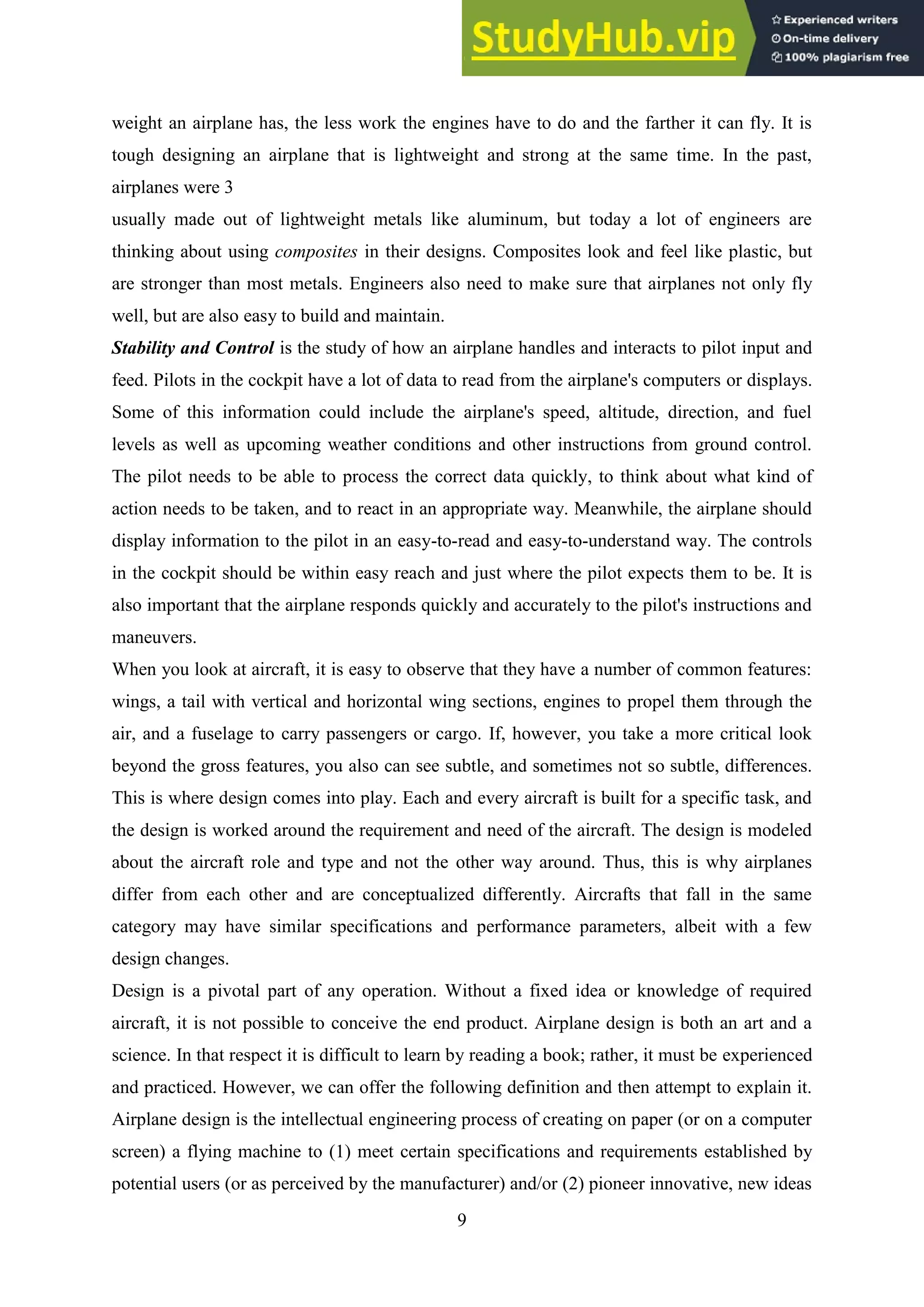
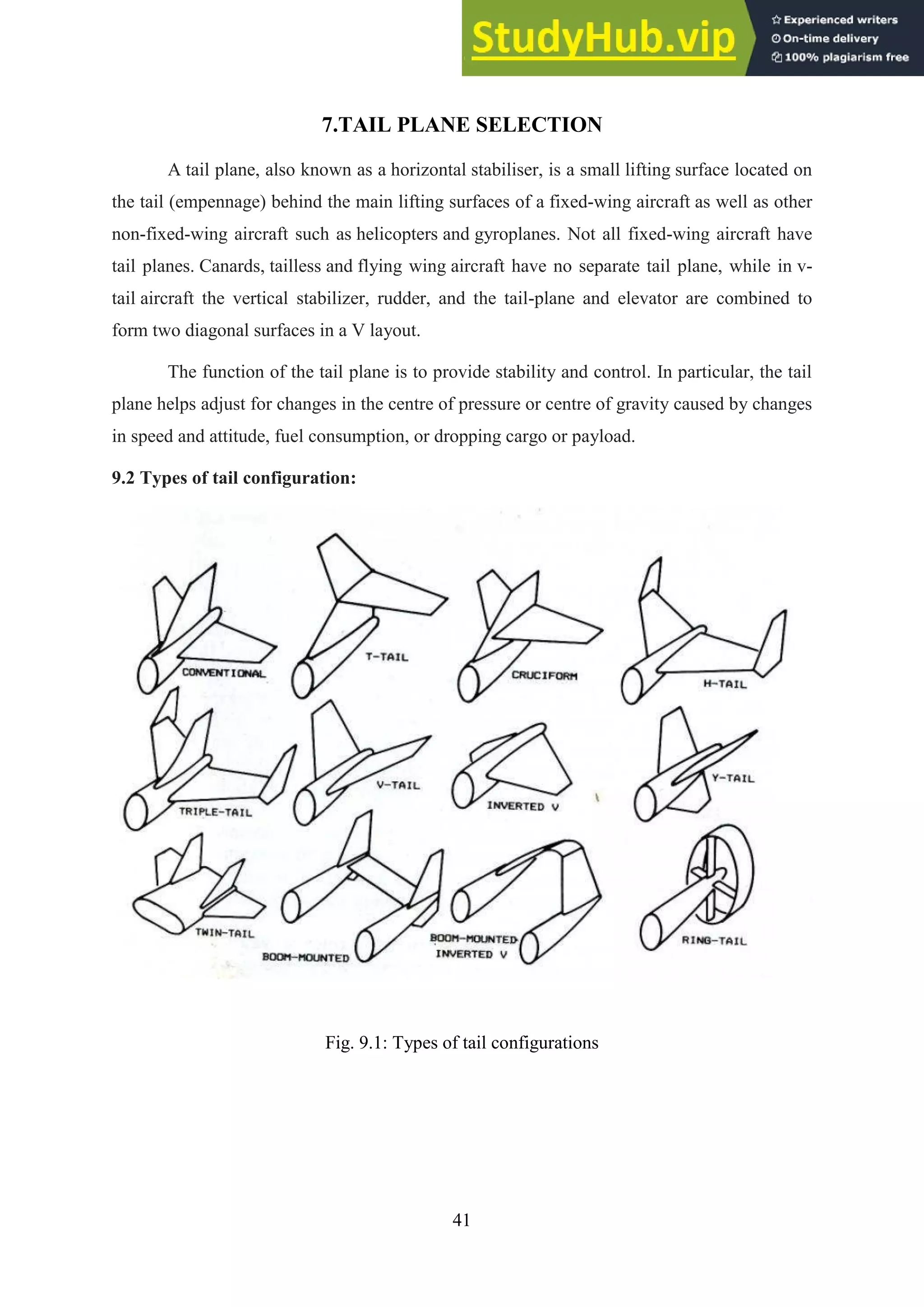
6.AIRFOIL AND WING SELECTION
Airfoil selection:
W = L = v2
S CL Wing
CL Wing = [
] =
where, V = stall velocity
S = wing area
= density at altitude (service ceiling)
= wing loading
CL Wing = Cl Airfoil = [
]
= 1.43
Figure 1
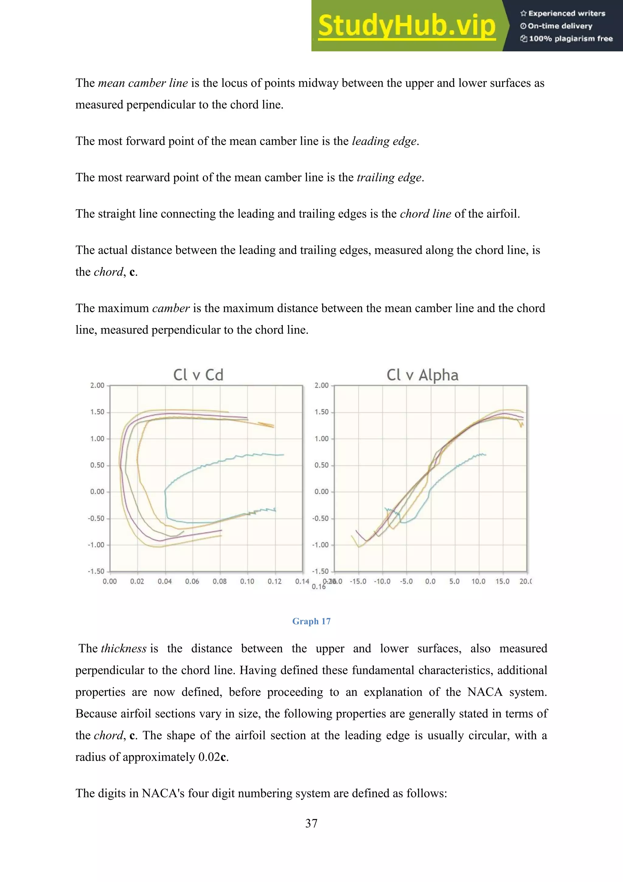
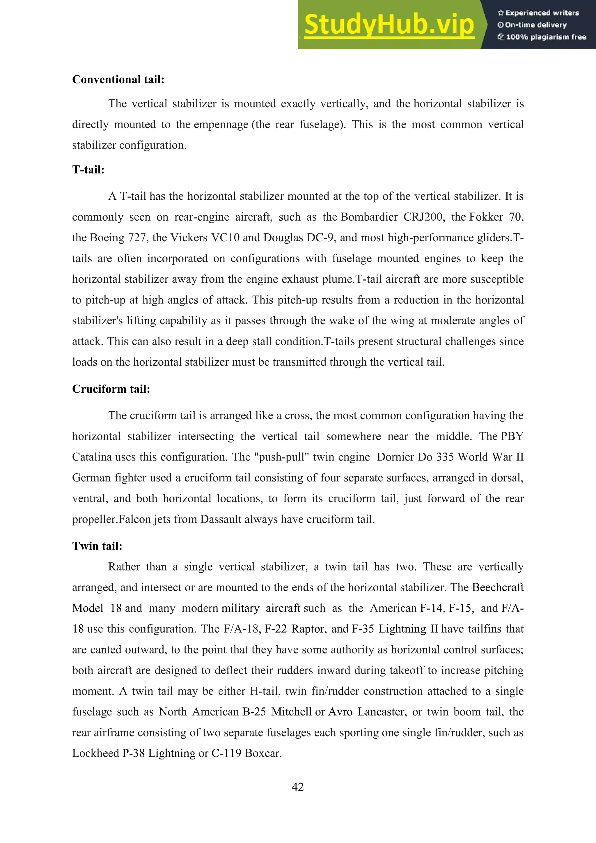
The first family of NACA airfoil sections, developed in the 1930s, was the "four-digit" series.
Following are some definitions of airfoil section characteristics, followed by a description of
how the NACA "four-digit" series specifies these characteristics.](https://image.slidesharecdn.com/aircraftdesignproject-ifighterjetsaprojectreport-230805215221-d8617a5a/75/AIRCRAFT-DESIGN-PROJECT-I-FIGHTER-JETS-A-PROJECT-REPORT-36-2048.jpg)
![40
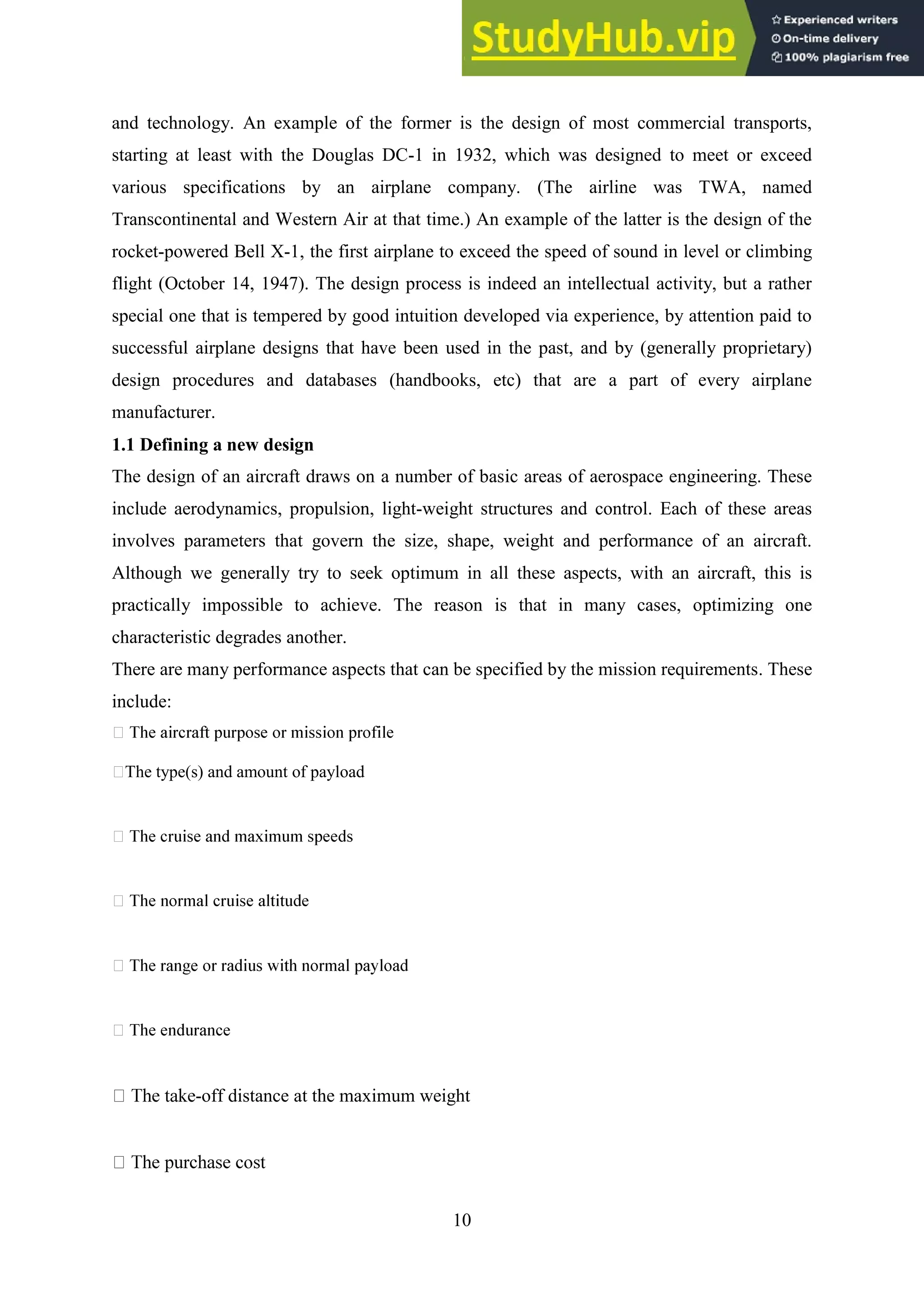
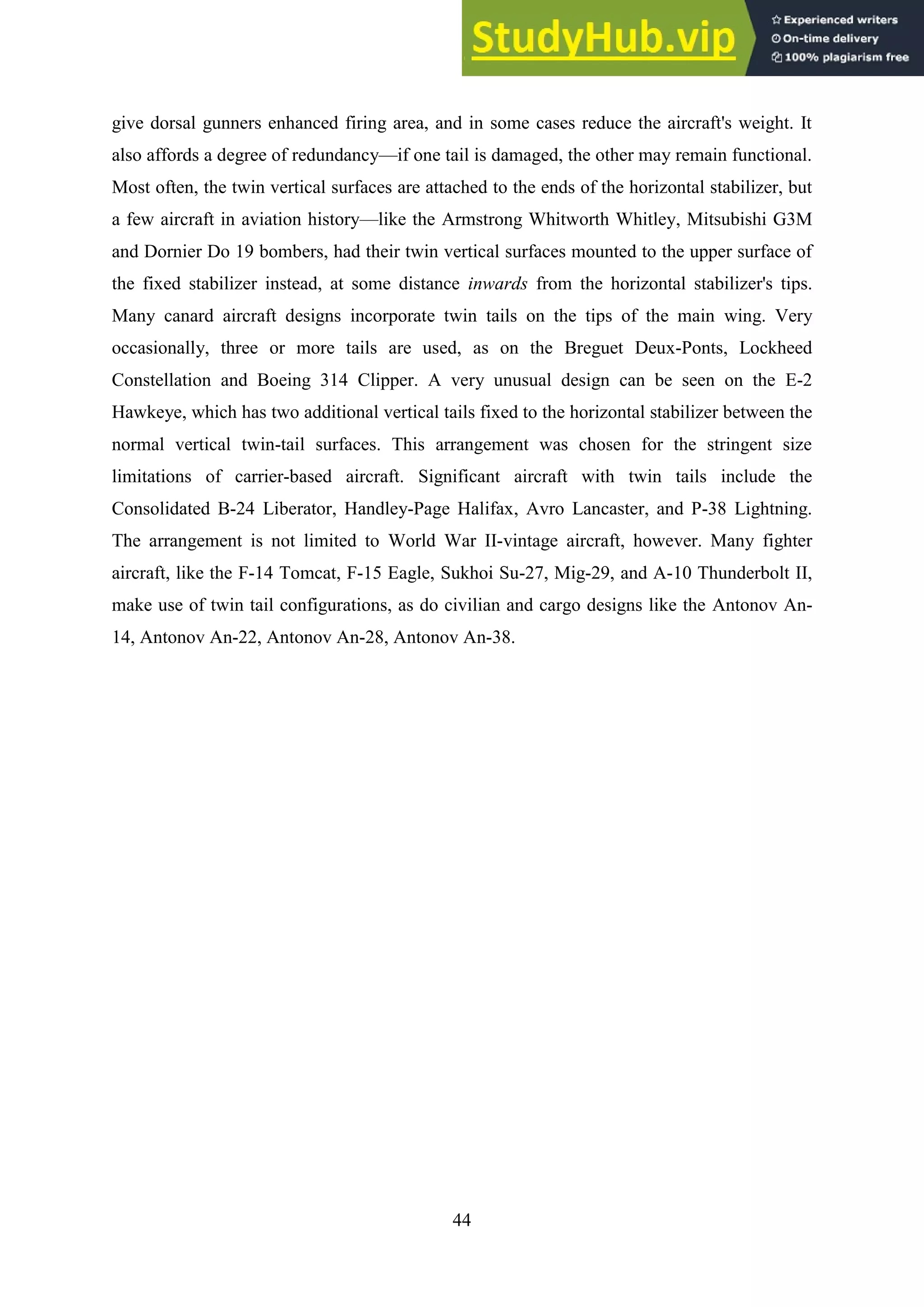
= 0.5 *5.79
= 2.89m
Sweep angle (from graph) = 31.8º
Mean aerodynamic centre
ŷ = [ ]
= 5.75m
ĉ = Croot
= 4.503m
Figure 4](https://image.slidesharecdn.com/aircraftdesignproject-ifighterjetsaprojectreport-230805215221-d8617a5a/75/AIRCRAFT-DESIGN-PROJECT-I-FIGHTER-JETS-A-PROJECT-REPORT-40-2048.jpg)
![43
Triple tail:
A variation on the twin tail, it has three vertical stabilizers. An example of this
configuration is the Lockheed Constellation. On the Constellation it was done to give the
airplane maximum vertical stabilizer area while keeping the overall height low enough so that
it could fit into maintenance hangars.
V-tail:
A V-tail has no distinct vertical or horizontal stabilizers. Rather, they are merged into
control surfaces known as ruddevators which control both pitch and yaw. The arrangement
looks like the letter V, and is also known as a butterfly tail. The Beechcraft Bonanza Model
35 uses this configuration, as does the F-117 Nighthawk, and many of Richard Schreder's HP
series of homebuilt gliders.
TWIN TAIL
A twin tail is a specific type of vertical stabilizer arrangement found on the
empennage of some aircraft. Two vertical stabilizers—often smaller on their own than a
single conventional tail would be—are mounted at the outside of the aircraft's horizontal
stabilizer. This arrangement is also known as an H-tail,[1]
as it resembles a capital "H" when
viewed from rear - these were used on a wide variety of World War II multi-engine designs
that saw mass production, especially on the American B-24 Liberator and B-25 Mitchell
bombers, the British Avro Lancaster and Handley-Page Halifax heavy bombers, and on the
Soviet Union's Petlyakov Pe-2 attack bomber.
A special case of twin tail is twin boom tail or double tail where the aft airframe
consists of two separate fuselages, "tail booms", which each have a rudder but are usually
connected by a single horizontal stabilizer. Examples of this construction are the twin-
engined Lockheed P-38 Lightning; Northrop P-61 Black Widow; Focke-Wulf Fw 189; the
single jet-engined de Havilland Vampire; cargo-carrying Fairchild C-119 Flying Boxcar and
the little known Transavia PL-12 Airtruk
DESIGN
Separating the control surfaces allows for additional rudder area or vertical surface
without requiring a massive single tail. On multi-engine propeller designs twin fin and
rudders operating in the propeller slipstream give greater rudder authority and improved
control at low airspeeds, and when taxiing. A twin tail can also simplify hangar requirements,](https://image.slidesharecdn.com/aircraftdesignproject-ifighterjetsaprojectreport-230805215221-d8617a5a/75/AIRCRAFT-DESIGN-PROJECT-I-FIGHTER-JETS-A-PROJECT-REPORT-43-2048.jpg)
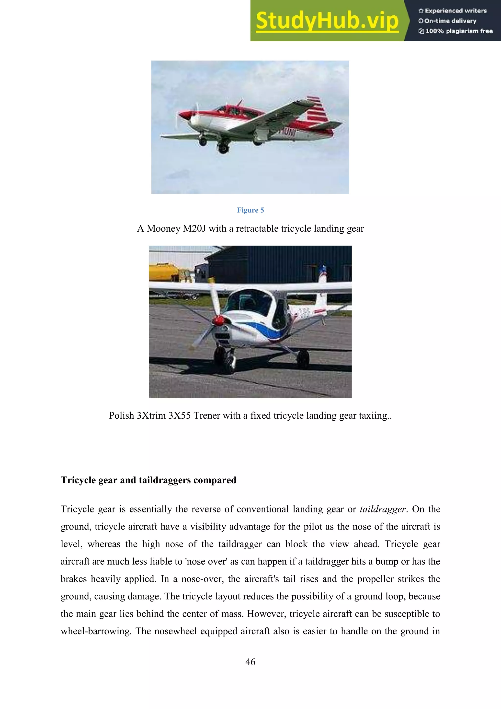
![47
high winds due to its wing negative angle of attack. Student pilots are able to safely master
nosewheel equipped aircraft more quickly.[2]
Tricycle gear aircraft are easier to land because the attitude required to land on the main gear
is the same as that required in the flare, and they are less vulnerable to crosswinds. As a
result, the majority of modern aircraft are fitted with tricycle gear. Almost all jet-powered
aircraft have been fitted with tricycle landing gear, to avoid the blast of hot, high-speed gases
causing damage to the ground surface, in particular runways and taxiways. The few
exceptions have included the Yakovlev Yak-15, the Supermarine Attacker, and prototypes
such as the Heinkel He 178, the first four prototypes (V1 through V4) of the Messerschmitt
Me 262, and the Nene powered version of the Vickers VC.1 Viking. Outside of the United
States — where the tricycle undercarriage had solidly begun to take root with its aircraft
firms before that nation's World War II involvement at the end of 1941 — the Heinkel firm in
World War II Germany began building airframe designs meant to use tricycle undercarriage
systems from their beginnings, as early as late 1939 with the Heinkel He 280 pioneering jet
fighter demonstrator series, and the unexpectedly successful Heinkel He 219 twin-engined
night fighter of 1942 origin.[4]
A Cessna 150 taildragger.
The taildragger configuration has its own advantages, and is arguably more suited to rougher
landing strips. The tailwheel makes the plane sit naturally in a nose-up attitude when on the
ground, which is useful for operations on unpaved gravel surfaces where debris could damage
the propeller. The tailwheel also transmits loads to the airframe in a way much less likely to
cause airframe damage when operating on rough fields. The small tailwheel is much lighter
and much less vulnerable than a nosewheel. Also, a fixed-gear taildragger exhibits less
interference drag and form drag in flight than a fixed-gear tricycle aircraft whose nosewheel
may sit directly in the propeller's slipstream. Tailwheels are smaller and cheaper to buy and
to maintain, and manhandling a tailwheel aircraft on the ground is easier. Most tailwheel
aircraft are lower in overall height and thus may fit in lower hangars. Tailwheel aircraft are
also more suitable for fitting with skis in wintertime.[2]](https://image.slidesharecdn.com/aircraftdesignproject-ifighterjetsaprojectreport-230805215221-d8617a5a/75/AIRCRAFT-DESIGN-PROJECT-I-FIGHTER-JETS-A-PROJECT-REPORT-47-2048.jpg)
![49
problems, the fuel consumption and thrust was comparable to the initial model–considerably
less than what the F-14 had been designed for.
In 1979, a derivative of the GE F101 turbofan called the F101-X was selected to power the F-
14 and was later designated the F110-GE-400. The primary difference between the F110-GE-
400 and the F110-GE-100 is length - the F110-GE-400 has a 50-inch (1.3 m) tailpipe
extension to suit the F-14 airframe, which is fitted downstream of the augmentor (afterburner
section). The F110-GE-400 engine produced 23,400 lbf (104 kN) of thrust with afterburner at
sea level, which rose to 30,200 lbf (134 kN) at Mach 0.9.[3]
This provided a significant
increase over the TF30's maximum thrust of 20,900 lbf (93 kN).[4]
These upgraded jets were
known as F-14Bs, as were production aircraft powered by the F110. The same engine also
powers the final variant of the aircraft, the F-14D.
F-16
The F-16 Fighting Falcon entered service powered by the Pratt & Whitney F100 afterburning
turbofan. Seeking a way to drive unit costs down, the USAF implemented the Alternative
Fighter Engine (AFE) program in 1984, under which the engine contract would be awarded
through competition. The F110 currently powers 86% of the USAF F-16C/Ds (June 2005).
The F110-GE-100 provides around 4,000 lbf (17.8 kN) more thrust than the F100-PW-200
and requires more air, which led to the increase in the area of the engine intake. The F-16C/D
Block 30/32s were the first to be built with a common engine bay, able to accept both
engines, with block 30s having the bigger intake (known as "Big Mouth") and block 32s
retaining the standard intake.
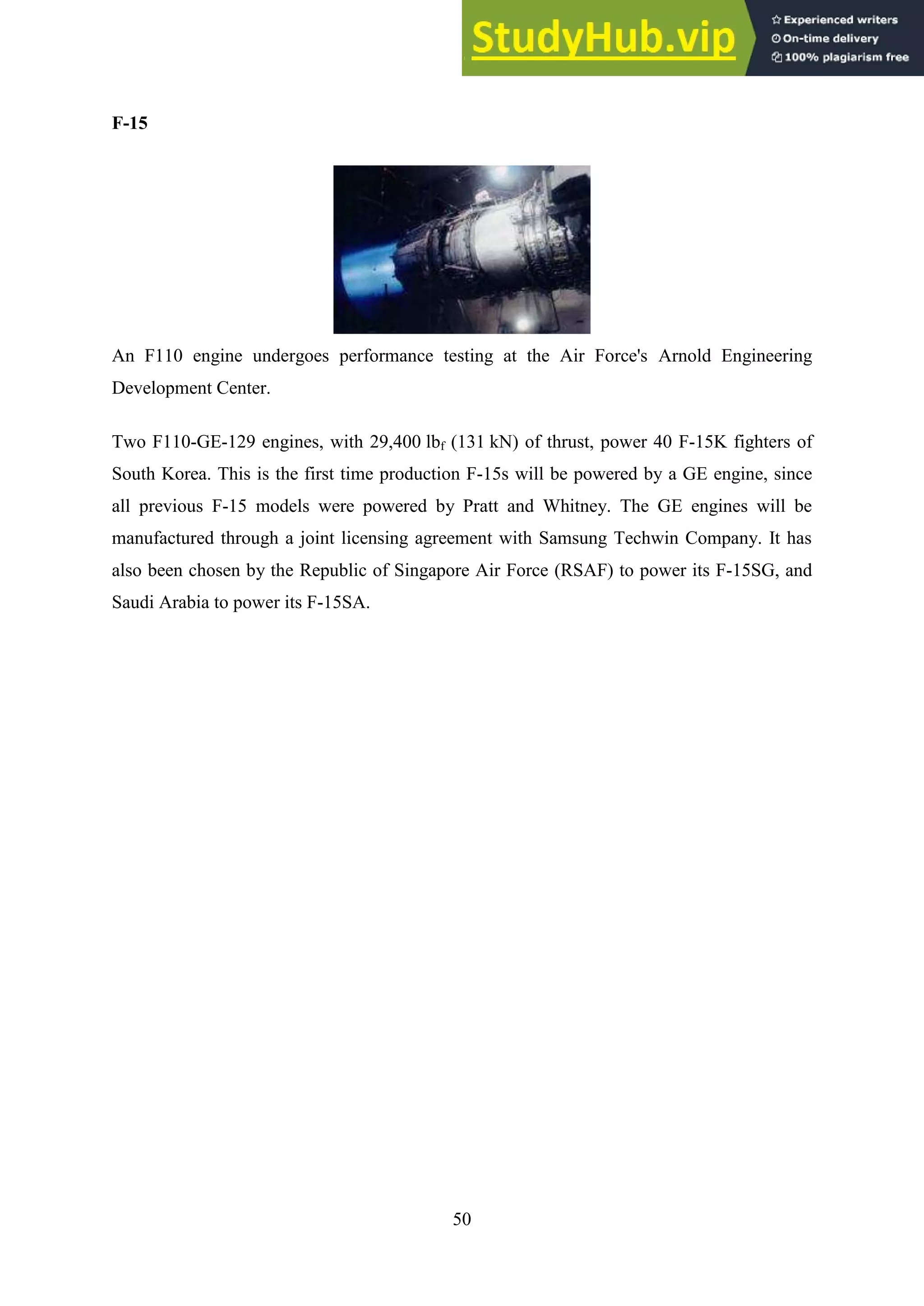
Initial orders were for the F110-GE-100 rated at 28,000 lbf (125 kN). Later versions of the
F110 include the F110-GE-129 delivering 29,400 lbf (131 kN) thrust and the F110-GE-132
delivering 32,000 lbS](https://image.slidesharecdn.com/aircraftdesignproject-ifighterjetsaprojectreport-230805215221-d8617a5a/75/AIRCRAFT-DESIGN-PROJECT-I-FIGHTER-JETS-A-PROJECT-REPORT-49-2048.jpg)


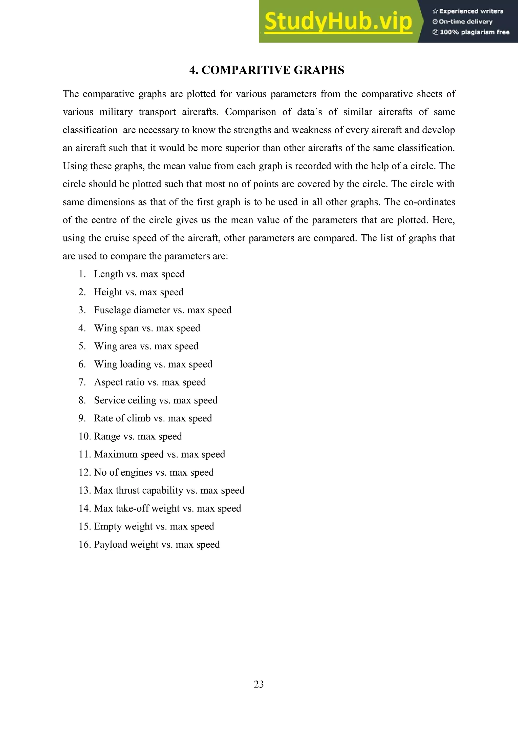
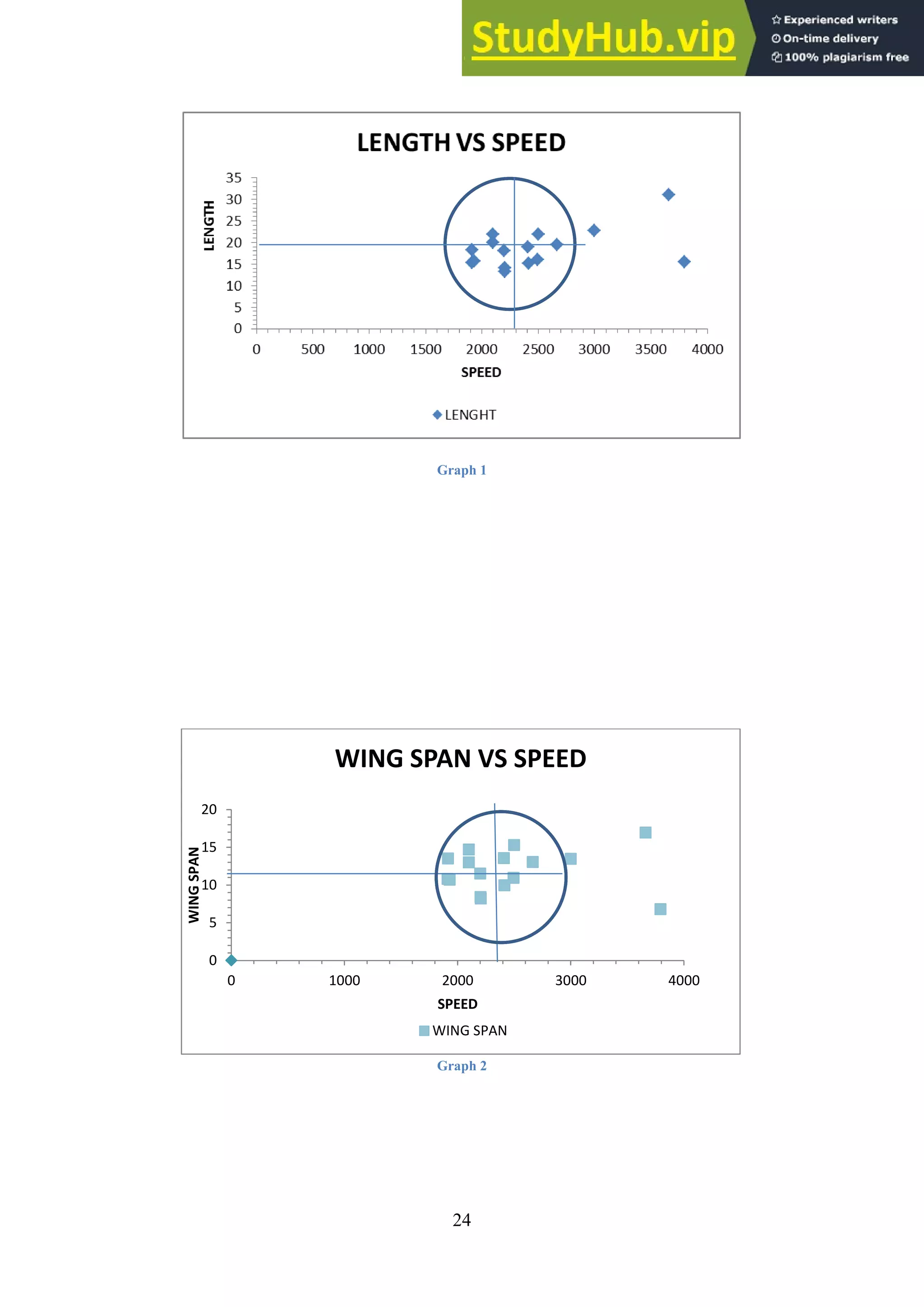
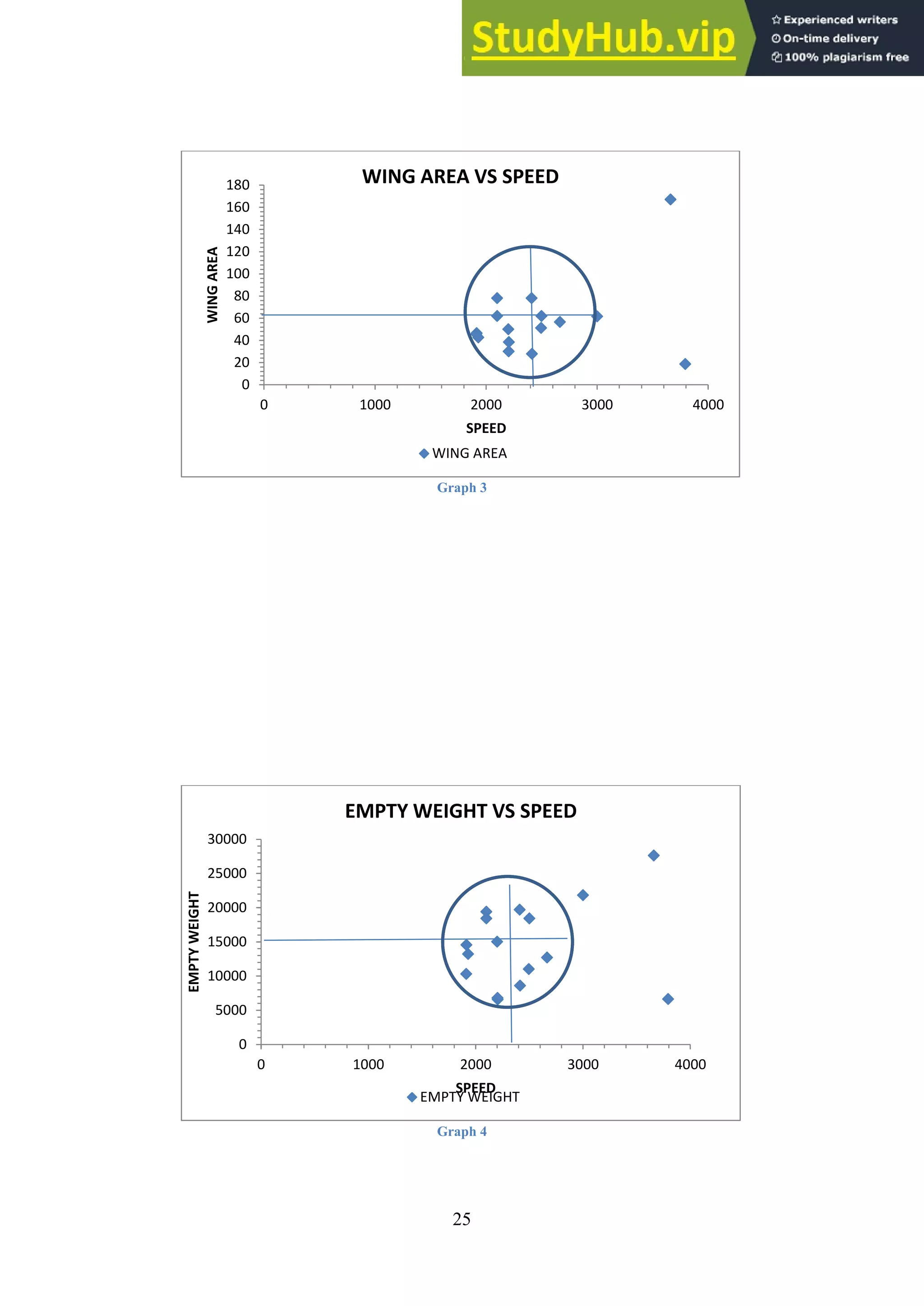
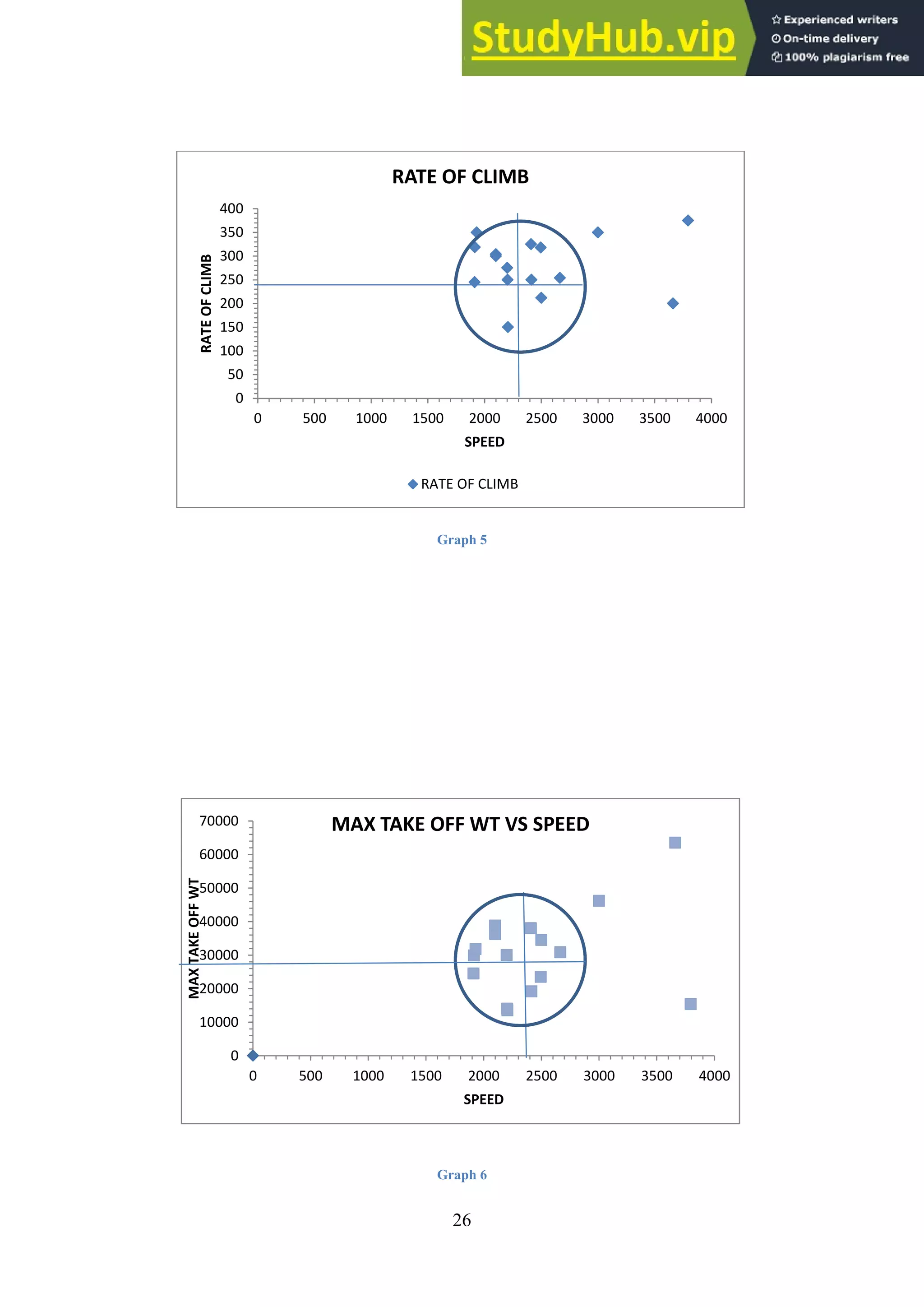
This document provides an overview of the design process for a fighter jet aircraft project. It includes acknowledgements, an abstract, table of contents, and sections on introduction to design, aircraft introduction, comparative details and graphs, weight estimation, airfoil and wing selection, tail plane, landing gear, power plant selection, drag estimation, V-N diagram, 3 view diagram, final parameters, and conclusion. The project involves students conceptualizing and designing a fighter jet to meet performance specifications while allowing for weapon carriage, efficiency, and reduced emissions.


