

![42
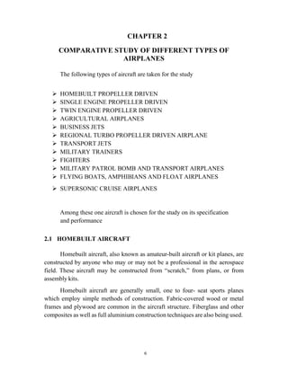
Rcr = 1378.90 nm
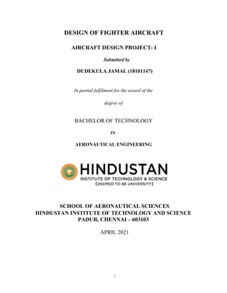
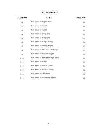
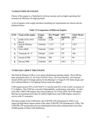
CHAPTER 6
WEIGHT ESTIMATION
6.1 INTRODUCTION
To find the weight of the following parameters of an aircraft.
Takeoff Weight (WTO)
Fuel Weight (WF)
Empty Weight (WE)
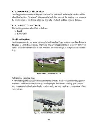
The following are the data which is obtained from the graph to proceed for the
Weight estimation.
Max Speed = 1,367.01 miles/hr
Takeoff weight = 35,273.96 lbs
Service ceiling (S.C) = 10.56 miles
Range = 1398.08 miles
Takeoff Distance (T.D) = 0.4319miles
Landing Distance (L.D) = 0.4048 miles
Payload = 16,534.67 lbs
RCR = R – [T.D + L.D + 2 x (S.C)]
Rcr = [1398.08 – (0.4319 + 0.4048 + (2 X 9.17))]
Where,
R – Total range = 1398.08 nm
T.D – Take off distance = 0.4319 nm
L.D – Landing distance = 0.4048 nm
Service ceiling = 9.17 nm](https://image.slidesharecdn.com/fighteraircraftdesignadp1-211125175324/85/Fighter-aircraft-design-adp-1-55-320.jpg)
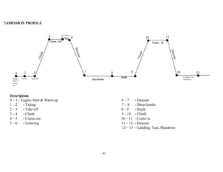

![47
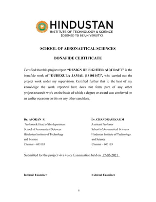
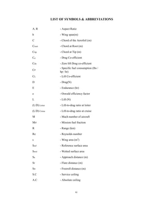
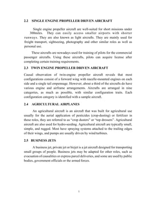
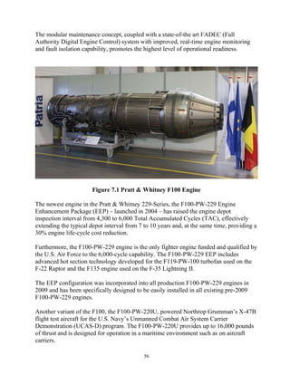
6.4 CALCULATION
Phase 1: Engine start and Warm-up
Begin weight is W0. End weight is W1. The ratio = 0.990
Phase 2: Taxi
Begin weight is W1. End weight is W2. The ratio = 0.990
Phase 3: Take-Off
Begin weight is W2. End weight is W3. The ratio = 0.990
Phase 4: Climb
Begin weight is W3. End weight is W4. The ratio = 0.971
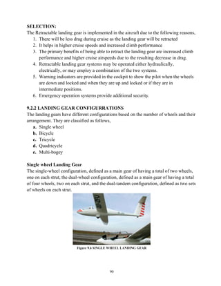
Phase 5: Cruise – out
Begin weight is W4. End weight is W5. The amount of fuel used during cruise can be
found from Brequet’s range equation mentioned below.
Rcr = [ ] cr [ ] cr ln [ ]
Rcr = [R – (T + L + (2 X service ceiling))] = 1378.90 nm
Rcr = [ ] cr [ ] cr ln [ ]
1378.90 = [
.
] [ 7 ] ln [ ]
Where,
V – Speed (from graph) = 1367 mph
𝐶𝑗 = 0.6
= 7
𝑾𝟓
𝑾𝟒
= 1.09](https://image.slidesharecdn.com/fighteraircraftdesignadp1-211125175324/85/Fighter-aircraft-design-adp-1-60-320.jpg)
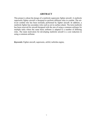
![48
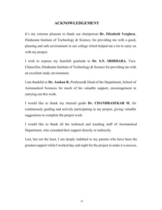
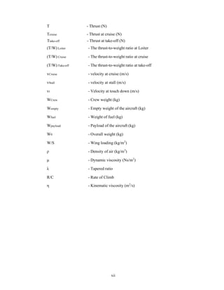
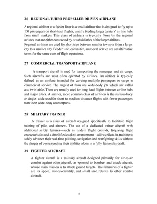
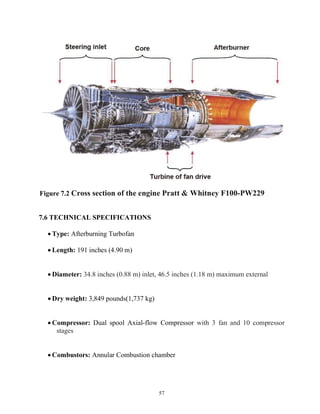
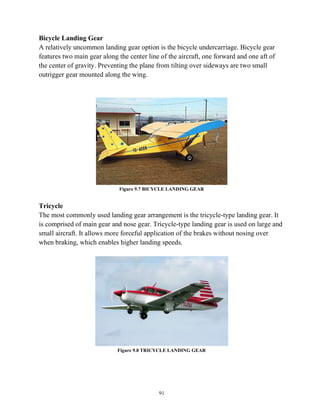
Phase 6: Loitering
Begin weight is W5. End weight is W6. The ratio W6/W5 can be estimate from the
Brequet’s endurance equation which is mentioned below.
Elt = [ ] lt [ ] lt ln [ ]
0.5 = [
.
] [ 9 ] ln [ ]
Where,
Elt = 30 mins of loitering = 0.5 hrs
The mission profile assumes no range credit during loiter. Loiter time is 30 minutes.
Cj = 0.6
= 9
𝑾𝟔
𝑾𝟓
= 0.947
Phase 7: Descent
Begin Weight is W6. End Weight is W7. No credit is taken for range. However, a
penalty for fuel used during descents from high altitudes needs to be assessed.
Typically, the ratio
= 0.99
Phase 8: Drop Bombs
Begin Weight is W8. End Weight is W9. Typically, the ratio
= 1
Phase 9: Strafe
Begin Weight is W9. End Weight is W10. Typically, the ratio
= 0.986
Phase 10: Climb
Begin Weight is W11. End Weight is W12. Typically, the ratio
= 0.969](https://image.slidesharecdn.com/fighteraircraftdesignadp1-211125175324/85/Fighter-aircraft-design-adp-1-61-320.jpg)
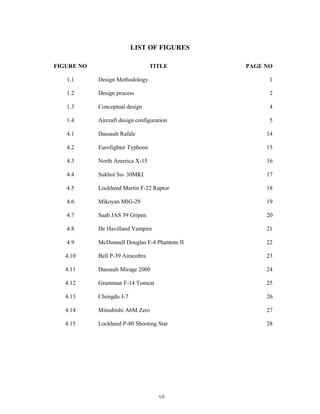
![50
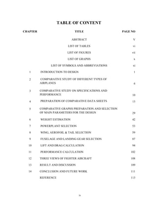
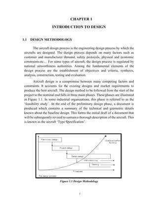
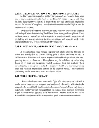
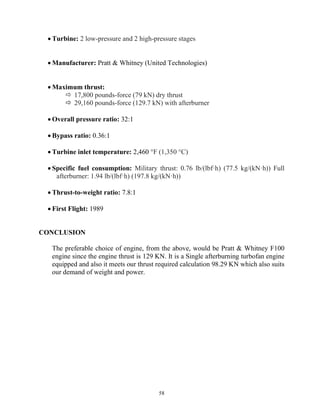
Phase 11: Cruise – in
Begin Weight is W12. End Weight is W13. Typically, the ratio
= 0.959
Phase 12: Descent
Begin Weight is W13. End Weight is W14. No credit is taken for range. However, a
penalty for fuel used during descents from high altitudes needs to be assessed. Typically,
the ratio
= 0.99
Phase 13: Landing, Taxi and shutdown
Begin Weight is W14. End Weight is W15. Typically, the ratio
= 0.995
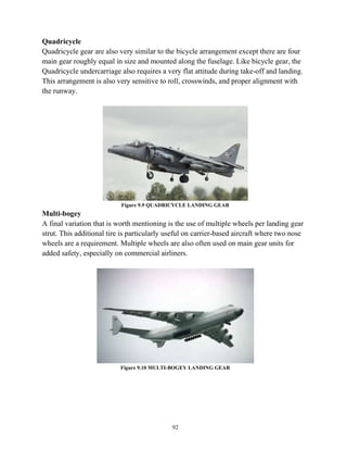
Mission Fuel – Fraction (Mf f)
The Overall mission fuel-fraction, Mff can now be computed as
Mf f =
Mf f = [(0.990) (0.990) (0.990) (0.971) (1.09) (0.947) (0.99) (1) (0.986) (0.969) (0.959)
(0.99) (0.995)]
Mf f = 0.947
Maximum Take-Off Weight (WTO)
WTO = 35,273.96 lbs
Payload Weight (Wpayload)
Wpayload = Weight of Number of Passengers + Military loads
= (242 * 0) + 16,534.67
Wpayload = 16,534.67 lbs](https://image.slidesharecdn.com/fighteraircraftdesignadp1-211125175324/85/Fighter-aircraft-design-adp-1-62-320.jpg)
![51
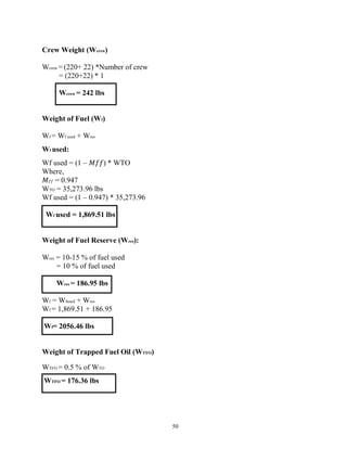
Weight of Operative Empty (WOE Tent)
WOE Tent = WTO – Wf – Wpayload
= 35,273.96 – 2056.46 – 16,534.67
WOE Tent = 16,682.83 lbs
Weight of Empty (WE Tent)
WE Tent= WOE Tent – WTFO – Wcrew
= 16,682.83 – 176.36 – 242
WE Tent = 16,264.47 lbs
Weight of Actual (WE Actual)
WE Actual= inv log10 [
10 , . –
], Where A = 0.5091; B = 0.9505
= inv log10 [
10 , . – .
.
]
WE Actual= 17,728.13 lbs
Difference between WE Actual and WE Tent
WE Actual – WE Tent= 17,728.13 – 16,264.47
WE Actual – WE Tent= 1463.66 lbs
Percentage of Error
% Error = [
E Actual – E Tent
E Actual
]* 100
= [
.
.
]* 100
% Error = 8.25 %](https://image.slidesharecdn.com/fighteraircraftdesignadp1-211125175324/85/Fighter-aircraft-design-adp-1-64-320.jpg)
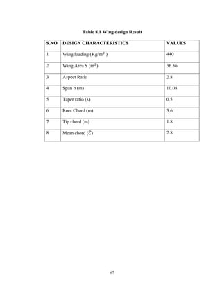
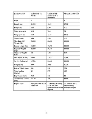
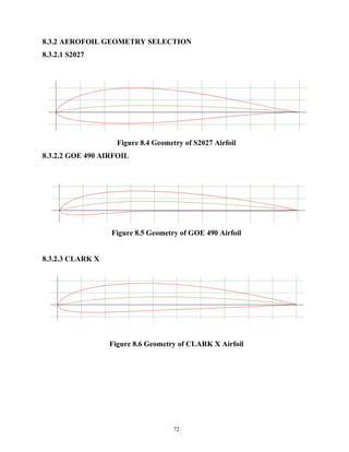
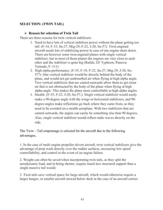
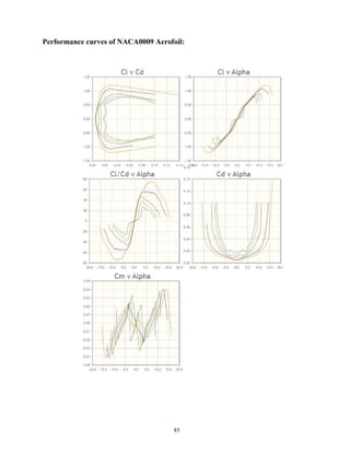
![70
NACA 4 Digit
1st digit: maximum camber (as % of chord).
2nd digit (x10): location of maximum camber (as % of chord from leading edge
(LE)).
3rd & 4th digits: maximum section thickness (as % of chord).
NACA 5 Digit
1st digit (x0.15): design lift coefficient.
2nd & 3rd digits (x0.5): location of maximum camber (as % of chord from LE).
4th & 5th digits: maximum section thickness (as % of chord).
NACA 6 Digit
1st digit: identifies the series type.
2nd digit (x10): location of minimum pressure (as % of chord from leading edge
(LE)).
3rd digit: indicates an acceptable range of CL above/below design value for
satisfactory low drag performance (as tenths of CL).
4th digit (x0.1): design CL.
5th & 6th digits: maximum section thickness (%c).
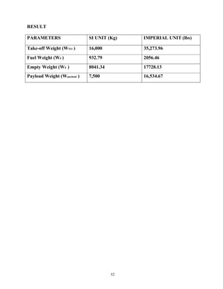
From the above list of aerofoil, the one chosen is the GOE 490 which have the suitable
lift coefficient for the current design.
Min Lift Coefficient can be calculated using below formula
W = L = 𝑣 SCL Wing
CL max = [
× × ×
]](https://image.slidesharecdn.com/fighteraircraftdesignadp1-211125175324/85/Fighter-aircraft-design-adp-1-83-320.jpg)
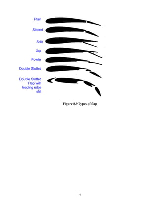
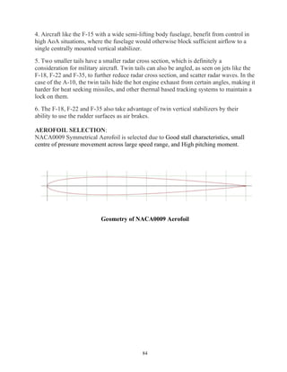
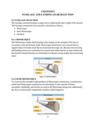
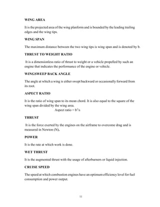
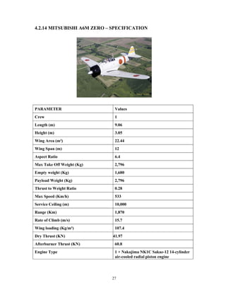
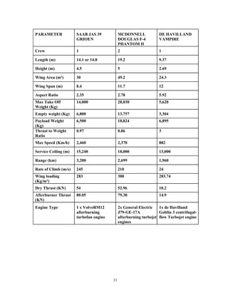
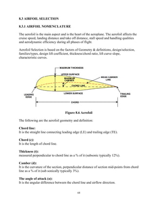
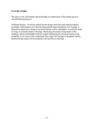
![99
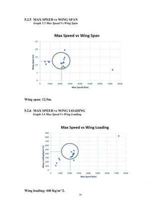
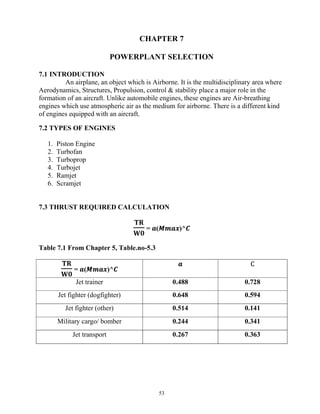
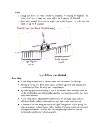
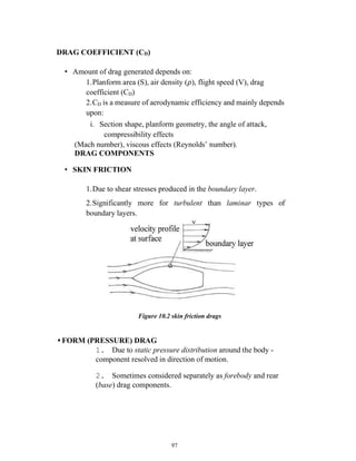
Figure 10.5 Typical streamlining effect
∅ = (16h/b)^2/1+ (16h/b)^2
h = height = 5.1 m
b = Wing span = 12.5 m
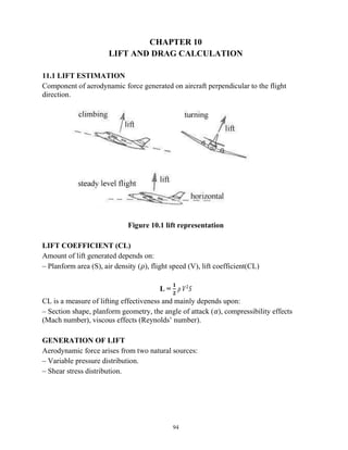
10.2.1 DRAG AT TAKE-OFF
𝐷 = 1/2 𝜌𝑉^2 𝑆[𝐶𝐷𝑂 + (∅𝐶𝐿𝑚𝑎𝑥^2/𝜋𝑒(𝐴𝑅)) ]
ρ = Density at sea level = 1.225 Kg/m3
Vstall = stalling speed = 57.21 m/s
V = 0.7*1.3*Vstall = 52.06 m/s
s = wing area = 48 m2
CLmax = coefficient of lift = 2
CDO = 0.003
∅= 0.97
∅ = 0.97](https://image.slidesharecdn.com/fighteraircraftdesignadp1-211125175324/85/Fighter-aircraft-design-adp-1-111-320.jpg)
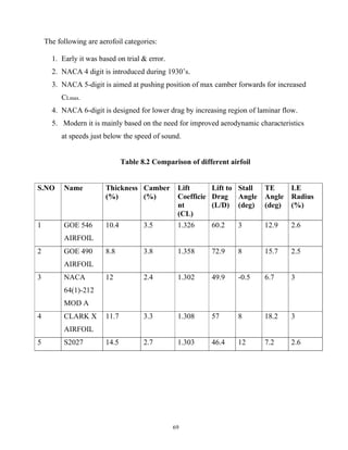
![100
Oswald efficiency factor e = 0.971
AR = Aspect Ratio = 2.8
D= 0.5 𝑋 1.225 𝑋(52.06)2
𝑋43.82 [0.003 +(0.97 X 2^2/𝜋 𝑋 0.971(2.8)) ]
10.2.2 DRAG AT CRUISE
𝐷 = 0.5 𝜌𝑉𝑐𝑟𝑢𝑖𝑠𝑒^2 𝑆[𝐶𝐷𝑂 + ∅𝐶𝐿𝑚𝑎𝑥/ 2 𝜋𝑒(𝐴𝑅) ]
ρ = Density at max altitude = 0.1539 Kg/m3
Vcruise = cruising speed = 597.2 m/s
s = wing area = 48 m2
CL = cruising lift coefficient = 0.121
CDO = 0.003
∅ = 0.9
Oswald efficiency factor e = 0.971
AR = Aspect Ratio = 2.8
D = 0.5 𝑋 0.1539 𝑋(597.2)^2𝑋 48 [0.003 + (0.97 𝑋 0.1212^2/ 𝜋 𝑋 0.971(2.8) ]
D = 6143.36 N
10.2.3 DRAG AT LANDING
D = 𝜌𝑉2𝑆[𝐶𝐷𝑂 +∅𝐶𝐿𝑚𝑎𝑥^2/ 𝜋𝑒(𝐴𝑅)]
ρ = Density at sea level = 1.225 Kg/m3
Vstall = stalling speed = 57.21 m/s
V = 0.7*1.2*Vstall = 48.05 m/s
s = wing area = 48 m2
D = 36.453 KN](https://image.slidesharecdn.com/fighteraircraftdesignadp1-211125175324/85/Fighter-aircraft-design-adp-1-112-320.jpg)
![101
CLmax
Maximum coefficient of lift = 2.35
CDO = 0.003
∅ = 0.97
Oswald efficiency factor e = 0.971
AR = Aspect Ratio = 2.8
D = 0.5 𝑋 1.225 𝑋(48.05)2𝑋 48 [0.003+(0.97 𝑋 2.352 /𝜋 𝑋 0.971(2.8) ]
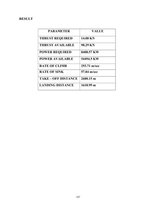
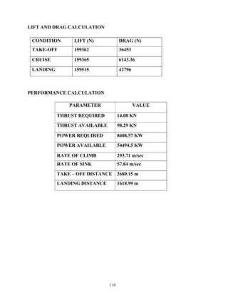
RESULT
CONDITION LIFT (N) DRAG (N)
TAKE OFF 159362 36453
CRUISE 159365 6143.36
LANDING 159515 42796
D = 42.796 KN](https://image.slidesharecdn.com/fighteraircraftdesignadp1-211125175324/85/Fighter-aircraft-design-adp-1-113-320.jpg)
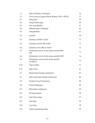
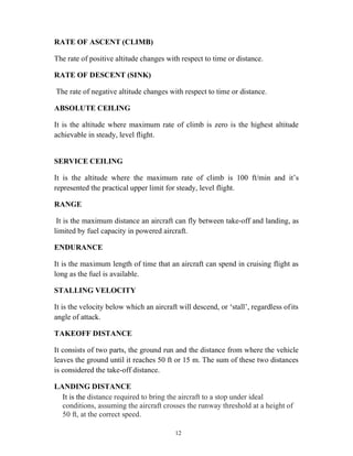
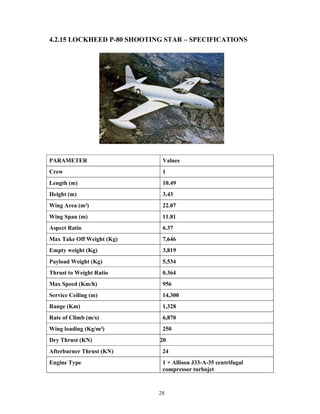
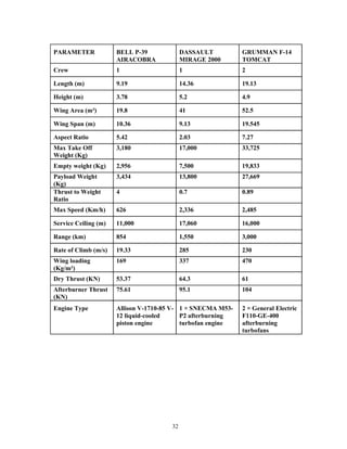
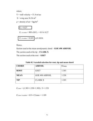
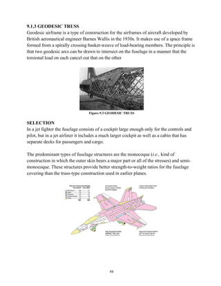
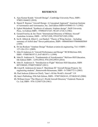
![104
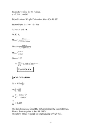
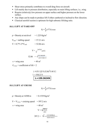
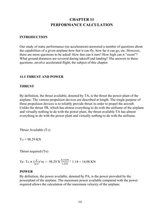
11.2 TAKE-OFF PERFORMANCE
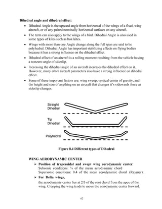
Figure 11.1 Take-Off Performance
Distance from rest to clearance of obstacle in flight path and usually
considered in two parts:
• Ground roll - rest to lift-off (SLO)
• Airborne distance - lift-off to specified height (35 ft FAR, 50 ft others).
The aircraft will accelerate up to lift-off speed (Vlo = about 1.2 x VStall) when it
will then be rotated.
A first-order approximation for ground roll take-off distance may be made from:
S LO= 144𝑊2
𝑔 𝑋 𝜌 𝑋 𝑆 𝑋 𝐶𝐿𝑚𝑎𝑥 X T
This shows its sensitivity to W (W2
) and 𝜌 (1/ 𝜌2 since T also varies with
𝜌). Slo may reduce by increasing T, S or Cl, max (high lift devices relate to latter
two).
An improved approximation for ground roll take-off distance may be made by
including drag, rolling resistance and ground effect terms.
S LO = 144𝑊2
𝑔 𝑋 𝜌 𝑋 𝑆 𝑋 𝐶𝐿𝑚𝑎𝑥 𝑋 {𝑇 − [𝐷 + 𝜇𝑟(𝑊 − 𝐿)]}𝑎𝑣
The bracketed term will vary with speed but an approximation may be made by
using an instantaneous value for when V = 0.7 x Vlo in the above equation:](https://image.slidesharecdn.com/fighteraircraftdesignadp1-211125175324/85/Fighter-aircraft-design-adp-1-116-320.jpg)
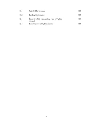
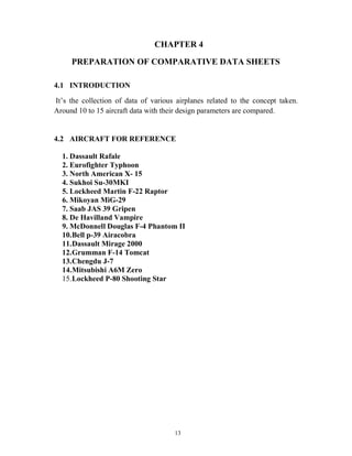
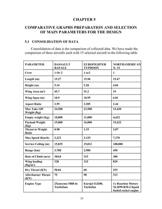
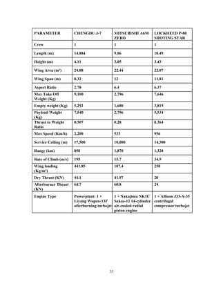
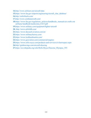
![105
𝐷 = 0.5 𝜌𝑉^2𝑆[𝐶𝐷𝑂 + (∅𝐶𝐿𝑚𝑎𝑥 ^2 /𝜋𝑒(𝐴𝑅)) ]
∅ = (16h/b)^2/1+ (16h/b)^2
Where ∅ accounts for drag reduction when in ground effect:
Where h = height above ground, b = wingspan.
𝜇𝑟 = 0.02 for smooth paved surface, 0.1 for grass.
CALCULATION
𝐷 = 0.5 𝜌𝑉^2𝑆[𝐶𝐷𝑂 + (∅𝐶𝐿𝑚𝑎𝑥 ^2 /𝜋𝑒(𝐴𝑅)) ]
𝑆𝐿𝑂 =
144 𝑋 (36453) 2
9..81 𝑋 1..225 𝑋48 𝑋 2 𝑋 {91250 − [98290 + 0.02(156910 − 159362)]}𝑎𝑣
SLO = 2680.15
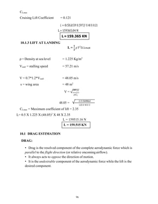
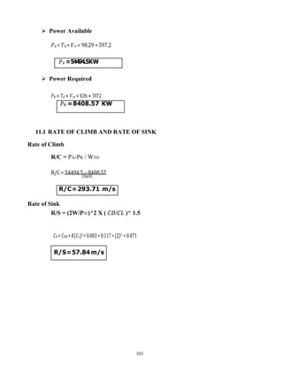
11.3 LANDING PERFORMANCE
Figure 11.2 Landing Performance](https://image.slidesharecdn.com/fighteraircraftdesignadp1-211125175324/85/Fighter-aircraft-design-adp-1-117-320.jpg)
![106
APPROACH & LANDING
Consists of three phases:
Airborne approach at constant glide angle (around 30
) and constant speed.
Flare - transitional manoeuver with airspeed reduced from about 1.3 VStall
down to touch-down speed.
Ground roll - from touch-down to rest.
Ground roll landing distance (s3 or s1) estimated from:
Where Vav may be taken as 0.7 x touch-down speed (Vt or V2) and Vt is
assumed as 1.3 x Vstall
S L = 1.69𝑊2
𝑔 𝑋 𝜌 𝑋 𝑆 𝑋 𝐶𝐿𝑚𝑎𝑥 X T𝑋 { [𝐷 + 𝜇𝑟(𝑊 − 𝐿)]}𝑎𝑣
𝜇𝑟 is higher than for take-off since brakes are applied - use 𝜇𝑟 = 0.4 for the
paved surface.
If thrust reversers (Tr) are applied, use:
S L = 1.69𝑊2
𝑔 𝑋 𝜌 𝑋 𝑆 𝑋 𝐶𝐿𝑚𝑎𝑥 X T𝑋 {𝑇 + [𝐷 + 𝜇𝑟(𝑊 − 𝐿)]}𝑎𝑣
CALCULATION
𝐷 = 0.5 𝜌𝑉^2𝑆[𝐶𝐷𝑂 + (∅𝐶𝐿𝑚𝑎𝑥 ^2 /𝜋𝑒(𝐴𝑅)) ]
𝑆𝐿=
1.63 𝑋 (42796) 2
9..81 𝑋 1..225 𝑋48 𝑋 2.35 𝑋 {98290 + [42796+ 0.02(156910 − 159362)]}𝑎𝑣
SL = 1618.99 m](https://image.slidesharecdn.com/fighteraircraftdesignadp1-211125175324/85/Fighter-aircraft-design-adp-1-118-320.jpg)
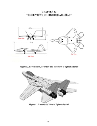

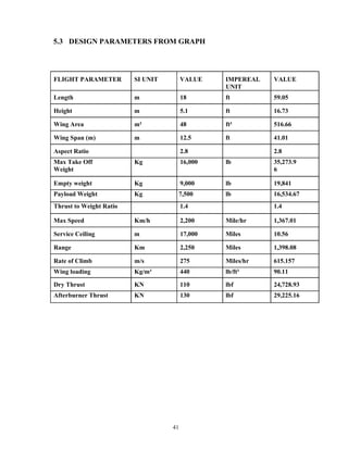
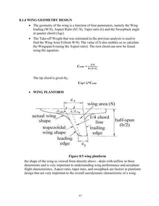
This document describes the design of a fighter aircraft. It discusses the conceptual design phase where the overall shape, size, weight and performance are determined. Comparative studies are conducted on different types of airplanes to select the appropriate configuration. Key parameters like wing type, engine selection and aerodynamic surfaces are analyzed and optimized. Performance calculations are carried out to evaluate the design. Three views and design specifications of the final fighter aircraft are presented.


