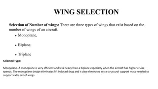
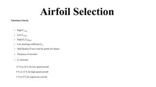
This document is an aircraft design project report for a twin engine business jet. It includes dimensions, weight configurations, and performance parameters for 20 existing medium business jets analyzed to determine ideal specifications for the new design. Weight estimation was conducted and various design elements were researched and selected, including a cantilever low wing with tapered airfoils. Performance calculations and graphs were included to analyze the 17-seater twin turbofan jet, which will have a maximum speed of 750mph. The report concludes with future work plans and references.


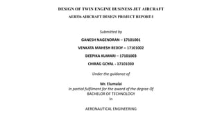

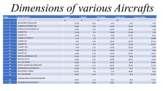
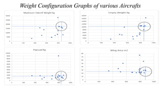
![• Estimated Maximum Take-off Weight = 39000 lb = 17000 kg
• Estimated Fuel Weight Wf = Wf used + Wreserved
= 9867 lb = 4475 kg
• % Error = % Error = [{(WE ACT - WE TENT)/WE ACT } * 100]
= 1.3%
WEIGHT ESTIMATION](https://image.slidesharecdn.com/presentation1-200730051101/85/Aircraft-Design-Project-1-15-320.jpg)
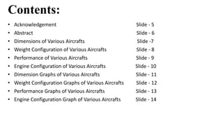
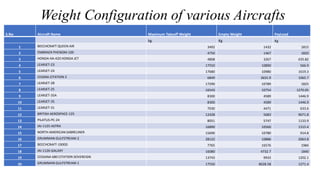
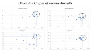
![Wing Setting Angle :
For Fighter αset = 0° to 1°
For Commercial αset = 3° to 5°
For Business Jet αset = 2° to 4°
For our Business Jet, we set the value of αset as 3°.
Wing Area (S): S = Max. Take-off Weight / Wing
Load = 25.45 m2
Aspect Ratio A.R: AR = b2 / S = 6.5
Chord Length c : c = b / AR = 1.97 m
Root Chord croot : 1.97 m
Tip Chord ctip : ctip = l * croot = 0.985 m
Mean Aerodynamic Chord MAC (ĉ): ĉ = [{(2/3)*cr
* (1+ l + l 2)/(1+ l )}] = 1.532 m
Structural Weight Volume : WF / ρF = 1.774 m3
Chord Thickness Ratio (t/c) : 20% of wt. volume = (t/c) * ĉ *
(0.5 * cr) * (0.5 * b)*1.5 = 0.03658
Root Thickness tr: tr = (t/c) * croot = 0.072
Tip Thickness tt: tt = (t/c) * ctip = 0.036
Wing Lift Coefficient CL : CL = [(2*WTO*g)/(ρ*v2
cruise*S)] = 0.2
Selected Airfoil
NACA 23024 is selected for wing root.
NACA 23012 is selected for wing tip.](https://image.slidesharecdn.com/presentation1-200730051101/85/Aircraft-Design-Project-1-21-320.jpg)
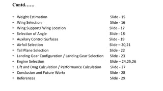
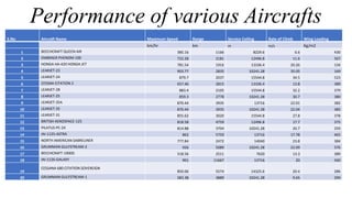
![LIFT AND DRAG CALCULATION
1. Lift calculation:
Lift during Takeoff L = (ρ*v2*s*CLmax)/2 = 6.82 KN
Lift during cruise L = 1/2 * ρ * v2 * s * Clmax =84.56 KN
Lift during Landing L =1/2 * ρ * v2 * s * Clmax =6.834 KN
2. Drag Calculation:
Drag during Take-off D = 1/2 * ρ * v2 * s * CD = 0.746 KN
Drag during cruise D = 1/2 * ρ * v2 * s * CD = 3.076 KN
Drag during Landing D = 1/2 * ρ * v2 * s * CD = 0.828 KN
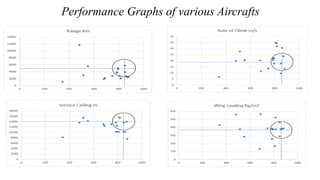
PERFORMANCE CALCULATION
Rate of climb R/C = [(Pa - Pr)/W] = 57.07 m/s
Rate of sink R/S = [(2*W/ρ)1/2 * (CD/CL)3/2] = 7.6 m/s
Take-off distance sLO = [(1.21 * WTO) / (g * ρ *s * CLmax
* (T/W))] = 21678.41 m.
Landing distance sL =
[{(1.69*W2)/(g*ρ*S*CLmax*(D+µr(W-L)))}] = 521.5 m](https://image.slidesharecdn.com/presentation1-200730051101/85/Aircraft-Design-Project-1-28-320.jpg)


![Aircraft 8 Passengers Design [RAVEN].](https://cdn.slidesharecdn.com/ss_thumbnails/designproject-191231232451-thumbnail.jpg?width=640&height=640&fit=bounds)


