SlideShare a Scribd company logo
1 of 70
Download to read offline
Mr. Geoffrey Allen Wardle. MSc. MSc. ATDA Airframe Design Study 2012-2020
ATDA STUDY PRESENTATION PART: - 3 ATDA FUSELAGE DESIGN, STRUCTURAL
LAYOUT, MANUFACTURE, AND MAJOR COMPONENT INTEGRATION.
ATDA Project Fuselage Structural Layout Aug 2020.
ATDA Project Fuselage Section 13/14
Structural Assembly Aug 2020.
ATDA Project Fuselage Cross - Section
through Section 15 looking Aft Aug 2020.
Mr. Geoffrey Allen Wardle. MSc. MSc. ATDA Airframe Design Study 2012-2020
This presentation has been created, for the sole purpose of private study and is not the work of a
company or government organisation it entirely the work of the author using resources in the public
domain. The final paper will be submitted for peer - review to the American Institute of Aeronautics
and Astronautics, Design Engineering Technical Committee, and the RAeS Structures and
Materials Group, for pre submission assessment. Readers must be aware that the work contained
may not be necessarily 100% correct, and caution should be exercised if this project or the data it
contains is being used for future work. If in doubt, please refer to the AIAA, Design Engineering
Technical Committee and the author.
All of the views and material contained within this document are the sole research of the author and
are not meant to directly imply the intentions of the Boeing Company, Airbus Group, GKN
Aerospace, or any contractor thereof, or any third party at this date. Although the USAF and NASA
have awarded contracts for studies into stitched composite transport aircraft structures, this work is
not the product of their results or any part of their body of research, and should not be considered
as such.
This document contains no material what so ever generated or conceived by myself or others
during my employment with BAE SYSTEMS (PLC), or that is governed by ITAR restrictions. This
work is solely my own creation and is based on my own academic studies and literature research
and the distribution of all information contained within this document is unlimited public release and
has been approved through the AIAA. This document and any part thereof cannot be reproduced
by any means in any format or used for any other research project without consultation with AIAA
Design Engineering Technical Committee or the author.
2
Presentation “Health” Warning.
.
Mr. Geoffrey Allen Wardle. MSc. MSc. ATDA Airframe Design Study 2012-2020
3
This is an overview covering my current private design trade studies into the incorporation of new
structural technologies and manufacturing processes into a future transport airframe design, and
the incorporation of mission adaptive wing (MAW) technology for per review through the AIAA
This study has been undertaken after my 13 years at BAE SYSTEMS MA&I, in airframe design
development as a Senior Design Engineer, and my Cranfield University MSc in Aircraft Engineering
completed in 2007(part-time), and was commenced in 2012 and I aim to complete it at the end of
2020. This utilises knowledge and skills bases developed throughout my career in aerospace,
academic studies and new research material I have studied, to produce a report and paper
exploring the limits to which an airframe research project can be perused using a virtual tool set,
and how the results can be presented for future research and manufacturing. The toolsets used are
Catia V5.R20 for design / analysis / kinematics / manufacturing simulation: PATRAN / NASTRAN for
analysis of composite structures: AeroDYNAMIC™ for analysis of aircraft OML / Structural Loads /
performance. This work will also form the basis for a PhD study, it is the product of my own
research, and has not in any part been produced or conceptualised during my employment with
BAE SYSTEMS or any company which is any part thereof.
About this presentation:-
This presentation is Part 3 of a series of 5 presentation Parts which cover the airframe major
structural component development and engine and landing gear integration, and assembly
manufacturing technologies. The contents of this presentation are given in the following slide.
Overview of my current research activities in aircraft design for the ATDA paper.
Mr. Geoffrey Allen Wardle. MSc. MSc. ATDA Airframe Design Study 2012-2020
 Section 1:- ATDA Overview and fuselage configuration options and manufacturing, selection:
 Section 2:- Structural loading, layout fuselage structural members and manufacturing:
 Section 3:- The integration of the wing into the fuselage wing carry through box:
 Section 4:- The integration of the empennage into the fuselage:
 Section 5:- The integration of the nose and main landing gear into the fuselage:
 Section 6:- The wing to fuselage belly fairing design (in work):
 Section 7:- The horizontal tail to fuselage interface and seal configuration (in work):
 Section 8:- Empennage flight control system device mechanical integration:
 Section 9:- Fuselage assembly automation (in work).
THIS WORK MAY NOT BE REPRODUCED WITHOUT EXPRESS PERMISSION OF MYSELF, and RAeS.
4
Table of contents of this ATDA Study Presentation Part 2.
Mr. Geoffrey Allen Wardle. MSc. MSc. ATDA Airframe Design Study 2012-2020
Currently I am conducting a conceptual design research into the application the Future Integrated
Structure (FIS) technology PRSEUS (using NASA/TM-2009-215955 (ref 1) and NASA/CR-2011-
216880 (ref 2), as my starting point) and mission adaptive flight control surfaces, to future large
transport aircraft, as detailed in charts 1 to 6, chart 7 shows the projected baseline operational
profile used in loads and fuel tank sizing calculations. This is a technical report for per review
through the AIAA, future PRSEUS studies and the work breakdowns are shown in charts 8,9,10.
The reference baseline aircraft selected is for a CFC twin engine 250-300 seat class aircraft design
of conventional configuration. Table 1 presents design data and figures 1(a)/(b) illustrate the
configuration of the Baseline ATDA aircraft, and figure 2 shows the supercritical airfoil selected the
ATDA aircraft. This conventional design using the current materials technology shown in figure 2,
and will be compared with an improved baseline design incorporating PRSEUS (FIS) technology
figures 5, 6, 7 and 8, and Mission Adaptive Wing MAW Control surfaces, figures 9 and 10, to be
designed using Catia V5.R20, to determine the structural / weight / and aerodynamic benefits at the
trade study level and finally more advanced aircraft design configurations will be used to determine
future potential applications. The study consists of three phases:- (1) The overall airframe
configuration design and parametric analysis using both classical analysis and the Jet306 /
AeroDYNAMIC V2.08 analysis tool set based on my Cranfield MSc: (2) The second is major
structural wing component layout of the airframe initial structure with preliminary systems
integration, and using Cranfield University methods and Catia V5.R20 GSA for structural sizing. (3)
The final design study for both versions of the wing reference and new build will consist of
parametric analysis, initial optimisation and structural layout and analysis and constitutes a
feasibility study proposal to determine the benefits, and constraints on such an application.
Section 1:- ATDA Overview, fuselage configuration options and selection.
5
Mr. Geoffrey Allen Wardle. MSc. MSc. ATDA Airframe Design Study 2012-2020
IMPERIAL DATA. METRIC DATA.
Wing Span (ft / in) 231 / 3.3 Wing Span (m) 70.52
Length (ft / in) 240/88 Length (m) 75.88
Wing Area (sq ft) 4,375.49 Wing Area (sq m) 406.481
Fuselage diameter (in) 235.83 Fuselage diameter (m) 5.99
Wing sweep angle 35° Wing sweep angle 35°
Fuselage Length (ft /in) 244 / 3.8 Fuselage Length 74.47
Engine number / type 2 X RR Trent XWB Engine number / type 2 X RR Trent XWB
T-O thrust (lb) 83,000 T-O thrust (kN) 369.0
Max weight (lb) 590,829 Max weight (tonnes) 268.9
Max Landing (lb) 451,940 Max Landing (tonnes) 205.0
Max speed (mph) 391 Max speed (km/h) 630
Mach No 0.89 Mach No 0.89
Range at OWE (miles) 9,631 Range at OWE (km) 15,500
Cruise Altitude (ft) 45,000 Cruise Altitude (m) 13,716
6
Table 1(a):- Initial Configuration Aircraft Data for the baseline ATDA study.
Mr. Geoffrey Allen Wardle. MSc. MSc. ATDA Airframe Design Study 2012-2020
Figure 1(a):- Overall configuration and dimensions of the ATDA baseline aircraft.
7
70.52m (231ft 3.3in) Code F
18.34m (60ft 7in)
11.51m (37ft 1.6in)
30.58m (100ft 3.8in)
O/A 75.87m (248ft 1.3in) Code E
74.47m (244ft 3.8in)
34.45m (113ft 2.4in)
O/A 75.27m (246ft 10.7in)
Fuselage sized for
twin aisle 9 abreast
2 LD-3 containers
5.99m (235.85in)
Section on ‘A’
‘A’
‘A’
17.85m
(58ft 4.6in)
11.92m (39.136ft)
7.771m
14.154m
17.248m
For all analysis measurements see Section 14
Mr. Geoffrey Allen Wardle. MSc. MSc. ATDA Airframe Design Study 2012-2020
Figure 1(b):- ATDA Configuration C of G, Tip back, and Overturn angles.
8
11.51m (37ft 1.6in)
75.87m (248ft 1.3in) Code E
74.47m (244ft 3.8in)
34.45m (113ft 2.4in)
17.85m
(58ft 4.6in)
Aft C of G 36.787m
C of G 36.089m
Fwd C of G 36.089m
Fwd C of G 36.089m
Aft C of G 36.787m
43°
57°
10°
NLG
MLG
75°
From analysis of the Catia Concept model Tip back angle = 10°: Overturn angle = 75°
Mr. Geoffrey Allen Wardle. MSc. MSc. ATDA Airframe Design Study 2012-2020
The ATDA Fuselage Baseline will use the skin panel structural layout of the Airbus A350 as the
initial structural starting point as the longitudinal joints participate in the fuselages bending
resistance and therefore imparts superior bending strength, and each panel can be optimised for
its specific design case as shown in figure 67(a), these panels being as long as practical to
minimise the number of circumferential joints. Although this is a more complex manufacturing
option than the Boeing 787 barrel option which allows a single process to be used throughout, as
shown in figure 67(b). The Airbus system offers greater compatibility with ATDA Prime fuselage
PRSEUS stitched stringer manufacturing technology, although the noes and tail are barrel sections,
shown in figure 67(c), figures 67(d)(e) shows cabin window sizing, location and planned capacity.
The ATDA Fuselage Baseline frame stations and build joints are shown in figure 68(a):- Section
11/12 to Section 13/14 joint is at Frame 21: Section 13/14 to Section 15 joint is at Frame 41:
Section 15 to Section 16/18 is at Frame 71: Section 16/18 to Section 19 join is at Frame 93: and
the Section 19 to Section 19.1 joint is at Frame 106. The build joint philosophy selected for the
ATDA Fuselage Baseline was the Airbus style lap joint with a splice strip located on frames, as
shown in figure 68(d). This was adopted in preference to the Boeing butt joint with splice strap
located between frames as shown in figure 68(c) which although easier to inspect and maintain but
was not seen to enable the direct coupling for high loads that Airbus style lap joint ensures. The
ATDA Fuselage frame design concept adopted the Boeing full depth bolted frames but with an I –
section, mounted over co-bonded hat stringers as shown in figure 68(e) and stitched to the skin,
this offered lower complexity and weight over the Airbus clip based philosophy. The ATDA
Fuselage Prime, with full depth frames over stitched stringers. Table 8 gives a comparison of frame
and stringer types and pitches from which the ATDA baseline values were derived.
9
Section 1:- ATDA Overview, fuselage configuration options and selection (cont.)
Mr. Geoffrey Allen Wardle. MSc. MSc. ATDA Airframe Design Study 2012-2020
10
Figure 2:- Advanced Technology Demonstrator Aircraft “Tube and Wing” 2030.
Composite Wings and
Empennage applied
PRSEUS stitched composite
technology.
All electric control system with
MAW technology and advanced
EHA actuation system.
Hybrid Laminar Flow
Control on wing
upper surface.
Composite Fuselage
applied PRSEUS stitched
composite stringers.
Natural Laminar
Flow on nacelles.
Advanced
Engines.
Variable Trailing
Edge Camber.
Wing aspect ratio >10.
Riblets on fuselage.
Hybrid Laminar Flow Control
on Vertical and Horizontal tails
.
SOFC/GT Hybrid APU.
Positive control winglets.
HT Thermoplastic
composite engine pylons.
Thermoplastic composite
fuselage frames.
Thermoplastic
composite Belly Fairing.
Mr. Geoffrey Allen Wardle. MSc. MSc. ATDA Airframe Design Study 2012-2020
11
PRSEUS stitched
composite technology
empennage 2016-2019.
PRSEUS stitched composite
technology wing 2013-2019.
Automated Assembly of wing
structure 2016-2020.
Thermoplastic composite
fuselage frames 2017-2018.
Positive control winglets
2016-2020.
Composite Fuselage applied
PRSEUS stitched composite
stringers 2017-2018.
Thermoplastic composite
Belly Fairing 2017-2019.
H Temp Thermoplastic
composite engine pylons
proposed 2016-2018.
Figure 3:- My Advanced Technology Demonstrator Aircraft Project Work Breakdown.
Wing Carry Trough Box Structure
defined and sized ( section 7).
Wing Torsion Box Structure
defined and sized (section 7).
Mr. Geoffrey Allen Wardle. MSc. MSc. ATDA Airframe Design Study 2012-2020
12
Figure 4:- ATDA Fuselage design build philosophy selected and panel sizing.
Analysis will be of Section 15 Panels initially.
(*Note Port and Stbd side panel dimensions are identical).
Fwd CFC Barrel Section
(B787 example).
Aft CFC Barrel Section
(A350 example).
Section 15 CFC Keel Panel
(A350 example).
Section 13/14 Crown panel:-
Area = 68.051m²: Length = 12.792m
Section 15 Crown panel:-
Area = 110.074m²: Length = 20.645m
Section 16/18 Crown panel:-
Area = 74.569m²: Length = 14.391m
Port Section 13/14 Side panel:-
Area = 39.176m²: Length = 12.792m
Port Section 15 Side panel:-
Area = 63.635m²: Length = 20.645m
Port Section 16/18 Side panel:-
Area = 47.865m²: Length = 14.391m
Section 13/14 Keel panel:-
Area = 87.734m²: Length = 12.792m
Section 15 Keel panel:-
Area = 92.423m²: Length = 20.645m
Section 16/18 Keel panel:-
Area = 94.923m²: Length = 14.391m
AIRBUS:- A350 XWB
Boeing:- B787
AIRBUS:- A350 XWB
Mr. Geoffrey Allen Wardle. MSc. MSc. ATDA Airframe Design Study 2012-2020
13
Figure 5:- ATDA Fuselage cabin window line cargo bay sizing and spacing.
Window C/L 1,750mm above
cabin floor top surface OML.
Clearance = 5cm
Clearance = 7.62cm
1.62m
1.87m
LD3 Container.
VIEW LOOKING AFT.
Planned Passenger capacity 320:- 48 in Business
class 6 abreast (8 rows) and 272 in Economy class 9
abreast (30 rows).
Planned cargo capacity 36 standard LD3 containers,
or 11 Pallets.
The proposed fuselage PRSEUS and thermoplastic application design and structural
development will use Airbus composite fuselage structural design philosophy with a
Boeing style CFC barrel cabin / nose section, and a CFC barrel tail section.
Composite Fuselage skins
with PRSEUS stitched
composite stringers.
Monolithic back to back C- section
Thermoplastic resin composite
fuselage frames.
Mr. Geoffrey Allen Wardle. MSc. MSc. ATDA Airframe Design Study 2012-2020
Overall loading on lifting surfaces:- Figure 15 illustrates the symmetrical flight case forces and
moments to be considered in wing structural design. The structural role of the wing includes the
following (ref 4):-
 The transmission of lift the force, which is balanced at the root by the air loads on the fuselage
and the stabilizer and by the inertial loads:
 The collection of the chord-wise air loads and the loads from control surfaces and high-lift device
hinges and the transfer of them to the main span-wise beam structure, which has to be achieved
by a series of chord-wise beams and gives rise to a torque on the span-wise structure as well as
contributing to the span-wise bending of the wing:
 The transfer to the main beam of the local inertia loads from the wing mounted powerplants, and
retracted main landing gear units:
 The reaction of landing loads from the main landing gear units:
 The pressure and inertia loads from integral fuel tanks and fuel:
 The provision of adequate torsional stiffness of the wing in order to satisfy the aeroelastic
requirements:
 The reaction of wing and landing gear drag loads and possibly, thrust loads in the plane of the
wing.
Figure 15 illustrates aircraft loading and considerations: Figures 16(a) through (c) illustrate
Symmetric:- span-wise, chord-wise, and fuselage loading. Figures 17(a) through (d) illustrate
Asymmetric (roll):- span-wise, fuselage torque, and fuselage sideslip and yaw loading, and figure
18(a) (b)and (c) illustrate overall ground and fuselage loading. 14
Section 4:- Overall loading on the aircraft primary structures.
Mr. Geoffrey Allen Wardle. MSc. MSc. ATDA Airframe Design Study 2012-2020
15
Figure 15(a):- Aircraft Structural Considerations.
Different Objectives - Different Configurations - Similar Process.
 RPV:-
 Long range:
 Loiter XX hours with out refuelling.
 Military Fighter / Attack: -
 Combat air and strike:
‫ח‬Z = 7.5g
 Passenger transport:-
 350 passengers:
 50 year service life:
 All weather:
 High reliability:
 Low maintenance:
 Damage tolerant.
Criteria:
Requirements:
Objectives:
 FAR’s:
 Mil specs:
 SOW/PDS.
External Loads
Environment:-
 Pressure:
 Inertial:
 Thermal:
 Acoustic.
Configuration
 Internal loads:
 Load paths.
Analysis
Sizing.
Methods:
Tests:
Allowables
Certification
reports
Mr. Geoffrey Allen Wardle. MSc. MSc. ATDA Airframe Design Study 2012-2020
Aircraft Structural Loads, Conditions, and Requirements.
Flight Loads:- Ground Loads: Other loads and Conditions:
Specific considerations are defined per:-
CFR14 Parts 23 and 25 …….(FAR)
CS-25 Book 1: SUBPART’s C and D
Both for commercial aircraft (CFR14 Subpart C = structures).
16
Overall loading on the aircraft primary structures (continued).
 Manoeuver
 Gust
 Control deflection
 Buffet
 Inertia
 Vibration.
 Vertical load factor
 Breaking
 Bumps
 Turns
 Aborted take-off
 Spin - up
 Spring back
 One wheel / two wheel
 Towing
 Ground winds
 Break away.
 Jacking
 Pressurisation
 Crash
 Actuation
 Bird strike
 Lightning strike
 Hail
 Power plant
 Thermal
 Fatigue
 Damage tolerance
 Fail safety
 Acoustic
 Ground handling.
Mr. Geoffrey Allen Wardle. MSc. MSc. ATDA Airframe Design Study 2012-2020
17
Figure 15(b):- Aircraft Structural Loads, Conditions and Requirements.
Typical commercial airliner critical static loads and conditions.
Gust.
Cabin Pressure.
Negative manoeuvre
and breaking.
Positive manoeuvre
and static gusts.
Positive dynamic gusts.
Aileron roll.
Negative manoeuvre.
Rudder kick:
Yaw manoeuvre:
Lateral gust.
Buffet.
Positive checked
manoeuvre.
Negative checked
manoeuvre.
Lateral manoeuvre.
Taxi.
Negative gusts.
Engine blade out.
N.B. Different load conditions
are critical for different area.
Mr. Geoffrey Allen Wardle. MSc. MSc. ATDA Airframe Design Study 2012-2020
18
Figure 15(c):- Overall loading on the aircraft wing surfaces.
Lw
Dw Lc
T
R
S
D
Wing inertias (structural / fuel) – relieve
all vertical and in-plane effects. Main landing gear.
R= Vertical – wing vertical shear, moment, torque.
D= Drag – wing in-plane shear, moment, torque.
S= Side – wing vertical moment.
Lw= Wing lift – wing vertical shear, moment, torque.
Lc= Control /high-lift devices – wing vertical shear, moment, torque.
Dw= Wing drag – wing in –plane shear, moment.
T = Thrust – wing in – plane shear, moment, torque.
Mr. Geoffrey Allen Wardle. MSc. MSc. ATDA Airframe Design Study 2012-2020
Symmetric flight cases:- Figure 16(a) illustrates the loading and corresponding form of the shear
force diagram across the wing of a twin engined low wing commercial airliner configuration similar
to the baseline study aircraft. Symmetric wing lift is relieved by the inertia of the structure, engines,
systems and fuel (see section 6). The overall loading on the wing is reacted at the side of the
fuselage at the wing root joint, and the bending moment is constant across the fuselage.
The loads on a typical chord-wise wing section are illustrated in figure 16(b), the sum of the
moments of the forces about a given chord-wise reference point yields the torque at that section,
and the integration of the local values of the torque across the span of the wing yields the overall
torque diagram.
Finally figure 16(c) illustrates the loading and the basic form of the shear force diagram along the
length of the fuselage of a twin engined low wing commercial airliner similar to the baseline study
aircraft. The shear force and bending moment due to the horizontal air-load are relived along the
fuselage by the transitional and rotational inertia effects. The net fuselage bending moment at the
fore and aft centre of gravity (c.g.) position is balanced by the sum of the wing torques at the sides
of the fuselage.
Asymmetric flight case:- The asymmetric flight cases are more complex than the symmetric
cases. A simplified example is the instantaneous application of aileron control on a wing having no
initial lift results in an asymmetric loading case, although in practice there is no true symmetry
between the up-rising and down-lowering ailerons. A more usual case is when the ailerons are
applied as the aircraft is in steady level flight as shown in figure 17(a).
19
Overall loading on the aircraft primary structures (continued).
Mr. Geoffrey Allen Wardle. MSc. MSc. ATDA Airframe Design Study 2012-2020
Figure 16(a):- Symmetric span – wise loading steady level flight condition.
20
Horizontal stabilizer load.
Span-wise airload.
Net distributed span-wise load.
Fuselage reactions.
Powerplant inertia. Powerplant inertia.
Span-wise inertia load.
SHEAR FORCE DIAGRAM.
Mr. Geoffrey Allen Wardle. MSc. MSc. ATDA Airframe Design Study 2012-2020
21
Powerplant weight.
Thrust -T
Aerodynamic moment - M
Control / Flap moment.
Aerodynamic Lift - L
Aerodynamic Drag - D
Control Force.
Control surface drag.
Wing structural systems
and fuel weight.
Figure 16(b):- Symmetric loading chord – wise torques on the aircraft wing.
Mr. Geoffrey Allen Wardle. MSc. MSc. ATDA Airframe Design Study 2012-2020
22
Figure 16(c):- Symmetric flight case fuselage loading.
Thrust.
Drag.
Horizontal stabilizer airload.
Aerodynamic moment from wing.
Wing lift.
Fuselage lift.
Centre of gravity.
Fuselage reaction.
Aircraft inertia.
Fuselage reaction
Stabilizer load
SHEAR FORCE DIAGRAM.
Idealizing the fuselage as a loaded beam under shear loading.
Mr. Geoffrey Allen Wardle. MSc. MSc. ATDA Airframe Design Study 2012-2020
Asymmetric flight case (continued):- The initial steady level flight condition will have a symmetric
loading as shown in figure 16(a). The aileron and the consequent roll effects are approximately anti-
symmetric in form figure 17(a). Figure 17(b) shows the shear force distribution due to this anti-
symmetric condition as well as the overall result of combining it with the symmetric diagram. In a
general rolling motion the couple resulting from the application of the aileron is balanced both by
the acceleration effect of the roll inertia and the aerodynamic effect due to the rate of roll (ref:-4).
The torque loading on the rear fuselage as a consequence of the application of the rudder control to
cause a sideslip motion is shown in figure 17(c). The torque due to the fin side load is increased by
the effect of asymmetric distribution of the trimming load on the horizontal stabilizer.
Figure 17(d) shows the plan view of the fuselage, illustrating how the fin side load is reacted by side
forces along the fuselage. The lateral bending along the fuselage is relived by sideslip and yaw
inertial effects and the net value at the wing root is balanced by wing aerodynamic forces and yaw
inertia. The torque on the fuselage is mainly reacted by the rolling inertia of the wing group.
Fuselage cyclic pressure loading is also very important and is considered in fuselage loadings later
in this study.
Ground loading cases:- The ground loading cases unlike the flight cases occur from local ground
forces. The take - off case is effectively a static balance of the aircraft weight by the vertical loads
on the nose – and main – wheels. However, the landing cases are not static in that even after the
wheels have made contact with the ground there is a translational motion of the centre of gravity of
the aircraft, as well as a rotation in pitch and, possibly, roll. It is also usual for the wing to be
providing lift at the time of wheel contact with the runway. Figures 18(a) and (b) illustrate the nature
of the landing gear span-wise loading, and the longitudinal loading.
Overall loading on the aircraft primary structures (continued).
23
Mr. Geoffrey Allen Wardle. MSc. MSc. ATDA Airframe Design Study 2012-2020
24
Figure 17(a):- Asymmetric (roll) span – wise loading flight condition.
Force due to aileron
application.
Net wing load in steady level flight.
Load due to rate of rotation in roll (roll damping).
Fuselage reactions – balance net
vertical force and rolling moment.
Resultant force and moment at fuselage Net moment is the difference of aileron, roll rate, and inertia effects.
Force due to aileron
application.
Mr. Geoffrey Allen Wardle. MSc. MSc. ATDA Airframe Design Study 2012-2020
25
Figure 17(b):- Asymmetric (roll) span – wise loading flight condition shear force diagrams.
Aircraft C/L
Powerplant inertia.
Anti-symmetric load.
Aircraft C/L
Fuselage reaction.
Overall.
Mr. Geoffrey Allen Wardle. MSc. MSc. ATDA Airframe Design Study 2012-2020
26
Reacting fuselage side
load (balanced by inertia
and wing-body air-load.
Fin side load.
Asymmetrical trim load on horizontal tail.
Reacting fuselage torque (balanced
mainly by wing rolling inertia.
Aircraft C/L
Figure 17(c):- Asymmetric loading flight condition fuselage torque.
Mr. Geoffrey Allen Wardle. MSc. MSc. ATDA Airframe Design Study 2012-2020
27
Figure 17(d):- Loading on the fuselage (sideslip, yaw and pressure).
Resultant side force – balanced by lateral (horizontal) inertia.
Fuselage side air-load (distributed along fuselage length.
Fin side load.
Moment at centre of gravity due to side loads –
balanced by yawing (rotational) inertia.
Cabin Pressurisation creates cyclic hoop tensile
stresses in the fuselage skin.
P
A
A
Section view on A
Mr. Geoffrey Allen Wardle. MSc. MSc. ATDA Airframe Design Study 2012-2020
Ground loading cases (continued):- The various forces and moments are balanced in the same
way as those arising in the flight cases, that is primarily by inertial effects. For this reason here the
ground contact forces are regarded as applied loads rather than as reacting forces.
Overall loading on the fuselage:- The loading determining the design of the fuselage is shown in
figure 18(c). The roles of the fuselage includes the following:-
 Provision of a pressurized (in commercial aircraft) envelope and structural support for the
payload (passengers and freight) and crew. The skin thickness required to limit hoop tensile
stresses to acceptable values is given by:- tp = ∆ρR / σρ Where:- ∆ρ is the maximum working differential
pressure: R is the local radius of the shell : and σρ is the allowable tensile working stress.
 To react landing gear, pressurization (in commercial aircraft), and powerplant loads when these
items are located on, or within the fuselage, the nose gear being always present.
 To transmit the control and trimming loads from the stabilizing / control surfaces to the centre of
the aircraft, and to provide support and volume for equipment and systems.
These requirements imply that to perform its structural role the fuselage has to be a longitudinal
beam loaded both vertically and laterally, it also has to react torsion and local concentrated loads,
the provision of a pressurized envelope implies a cylindrical encapsulated construction, with
pressure bulkheads. Therefore a conventional commercial airliner fuselage of circular cross section,
cabin floor, and cargo bay floor, with pressurized cabin, and external powerplants is the baseline
ATDA airframe.
28
Overall loading on the aircraft primary structures (continued).
Mr. Geoffrey Allen Wardle. MSc. MSc. ATDA Airframe Design Study 2012-2020
29
Figure 18(a):- Ground loading span – wise.
S
Ground vertical loads = R R R
Ground side loads = S
Resultant force and moment at fuselage.
Net wing load.
Fuselage reaction to balance vertical and side loads and rolling moment
due to side load – balanced by roll, vertical and horizontal inertias.
Mr. Geoffrey Allen Wardle. MSc. MSc. ATDA Airframe Design Study 2012-2020
30
Ground vertical loads = R R
D Ground drag loads = D
Fuselage vertical force – reacted
by vertical (translational) inertia.
Fuselage bending moment – reacted
by pitch (rotational) inertia.
Overall lift and weight in balance.
Figure 18(b):- Ground loading longitudinal.
Mr. Geoffrey Allen Wardle. MSc. MSc. ATDA Airframe Design Study 2012-2020
31
Figure 18(c):- Overall loading on the fuselage.
LF
LT
D
R
S
D
R
S
Main landing gear.
Nose landing gear.
LF = Fin load – fuselage horizontal shear, moment, torque:
LT = Tail load – fuselage vertical shear, moment, torque.
R = Vertical - fuselage vertical shear moment:
D = Drag – fuselage vertical shear moment:
S = Side – fuselage horizontal shear, moment, torque.
Cabin Pressurisation creates cyclic hoop tensile stresses in the fuselage skin.
P
Mr. Geoffrey Allen Wardle. MSc. MSc. ATDA Airframe Design Study 2012-2020
32
Figure 19(b):- Internal loads / Load Paths.
Thrust.
Drag.
Horizontal stabilizer lift load.
Aerodynamic moment from wing.
Wing lift.
Fuselage lift.
Centre of gravity.
Aircraft
weight.
Balance Load.
 Considering all load conditions and requirements:
 Developing a static load balance for each critical condition: This was done
- Apply loads realistically; for local loads as
- Determining where these loads are going to be balanced; well as for general
 Cutting sections to determine local internal loads: vehicle loads.
 Providing a path for the loads to follow (taking account that they follow the stiffest path):
 Considering that most structural members perform more than one function.
Getting the internal members to carry the airframe loads efficiently.
Mr. Geoffrey Allen Wardle. MSc. MSc. ATDA Airframe Design Study 2012-2020
33
Figure 19(c):- Internal loading / load paths in the fuselage.
Considering the fuselage acting as a beam.
Bending moment is carried
based on an Mc/I distribution.
The Keel beam is added to restore the load path along the bottom of the
fuselage removed when skin cutouts ware made for the wing carry
through box and main landing gear.
Lower longerons with effective skin carry
compression axial loads due to bending
moment.
Skin carry shear load
in - plane with VQ/I
distribution.
Crown skins and longerons
carry tension loads due to
bending moment.
For a downward tail load the
fuselage carries a shear and a
bending moment.
Mr. Geoffrey Allen Wardle. MSc. MSc. ATDA Airframe Design Study 2012-2020
34
Figure 19(d):- Design difference military use multiple longerons to bending.
Figure 19(d)ii:- Commercial transport aircraft and freighters use skin stringers resist
fuselage bending and have ring frames and pressure bulkheads.
Figure 19(d)i:- F-22A Like all fighter aircraft use longerons to resist
fuselage bending and have full section bulkhead and mate frames.
Mr. Geoffrey Allen Wardle. MSc. MSc. ATDA Airframe Design Study 2012-2020
Table 3(b):- Materials Properties for FATA fuselage materials (Ref.22).
Property. Unidirectional Tape /Slit Tape. Plain Weave Fabric.
Thickness per ply 0.15mm 0.25mm
Density (ρ) 1790kg/m 1570kg/m
Longitudinal modulus E1 (GPa) 137.3 62.6
Transverse modulus E2 (GPa) 7.8 59.3
In-plain Shear modulus G12 (GPa) 5.23 4.6
Poisson's ratio V12 0.36 0.062
Longitudinal tensile strength F1t (MPa) 2057 621
Transverse tensile strength F2t (MPa) 46.9 594
Longitudinal compressive strength F1c (MPa) 1610 760
Transference compressive strength F2c (MPa) 207 707
In-plain shear strength F6 (MPa) 135 125
Standard Width ATL* 460mm / AFP* 12.5mm 1600 mm
35
*ATL= Automated Tape Laying : AFP = Automated Fibre Placement.
3 3
Mr. Geoffrey Allen Wardle. MSc. MSc. ATDA Airframe Design Study 2012-2020
Category. Failure Mode. Weight Ratio (W2 / W1)
1 Tensile strength. ρ2 / ρ1 σe1/σe2 [kth1/ kth2 kθ1/kθ2]
2 Compressive strength. ρ2 /ρ1 σe1/σe2 [kch1/kch2 kθ1/kθ2]
3 Crippling ρ2 / ρ1 [Es1 σe1 / Es2 σe2]
4 Compression surface column and crippling ρ2/ρ1 [Es1 Et1 σe1/Es2 Et2 σe2]
5 Buckling compression and shear ρ2 /ρ1 [E1 / E2]
6 Aeroelastic stiffness ρ2/ρ1 E1/E2
7 Durability and damage tolerance ρ2/ρ1 [kd1kθ1/kd2kθ2]
36
Table 4:- Weight Ratio Equations for Various Failure Categories (based on Ref.6).
0.25
0.2
1/3
Mr. Geoffrey Allen Wardle. MSc. MSc. ATDA Airframe Design Study 2012-2020
Material Code
Weight Ratio (S1/S2) (ρ2/ρ1)
Cat 1 Cat 2 Cat 3 Cat 5 Cat 6 Cat 7(a) Cat 7(b)
Carbon /
epoxy
3501/6QI 0.4 0.4 0.5 0.4 0.6 0.2 0.7
Carbon /
epoxy
3501/6O 0.4 0.3 0.4 0.4 0.5 0.1 0.6
Titanium Ti6Al4V 0.5 0.5 1.1 1.0 1.0 0.8 0.5
Aluminium /
Lithium
8090T3X 0.9 0.9 0.9 0.9 0.8 0.7 0.9
Aluminium
alloy
7075 T76 0.7 0.7 0.9 0.9 1.0 0.7 0.7
Aluminium
alloy
2024 T3 1.0 1.0 1.0 1.0 1.0 1.0 1.0
37
Table 5:- Weight Ratios for Airframe Materials for Various Failure Categories (Ref.6).
n
Mr. Geoffrey Allen Wardle. MSc. MSc. ATDA Airframe Design Study 2012-2020
Figure 31:- Woven Cloth Classifications and surface ply BVID protection options trades.
38
Mr. Geoffrey Allen Wardle. MSc. MSc. ATDA Airframe Design Study 2012-2020
The ATDA Fuselage Baseline will use the skin panel structural layout of the Airbus A350 as the
initial structural starting point as the longitudinal joints participate in the fuselages bending
resistance and therefore imparts superior bending strength, and each panel can be optimised for
its specific design case as shown in figure 67(a), these panels being as long as practical to
minimise the number of circumferential joints. Although this is a more complex manufacturing
option than the Boeing 787 barrel option which allows a single process to be used throughout, as
shown in figure 67(b). The Airbus system offers greater compatibility with ATDA Prime fuselage
PRSEUS stitched stringer manufacturing technology, although the noes and tail are barrel sections,
shown in figure 67(c), figures 67(d)(e) shows cabin window sizing, location and planned capacity.
The ATDA Fuselage Baseline frame stations and build joints are shown in figure 68(a):- Section
11/12 to Section 13/14 joint is at Frame 21: Section 13/14 to Section 15 joint is at Frame 41:
Section 15 to Section 16/18 is at Frame 71: Section 16/18 to Section 19 join is at Frame 93: and
the Section 19 to Section 19.1 joint is at Frame 106. The build joint philosophy selected for the
ATDA Fuselage Baseline was the Airbus style lap joint with a splice strip located on frames, as
shown in figure 68(d). This was adopted in preference to the Boeing butt joint with splice strap
located between frames as shown in figure 68(c) which although easier to inspect and maintain but
was not seen to enable the direct coupling for high loads that Airbus style lap joint ensures. The
ATDA Fuselage frame design concept adopted the Boeing full depth bolted frames but with an I –
section, mounted over co-bonded hat stringers as shown in figure 68(e) and stitched to the skin,
this offered lower complexity and weight over the Airbus clip based philosophy. The ATDA
Fuselage Prime, with full depth frames over stitched stringers. Table 8 gives a comparison of frame
and stringer types and pitches from which the ATDA baseline values were derived.
39
Section 8:- The design and structural layout of the ATDA fuselage.
Mr. Geoffrey Allen Wardle. MSc. MSc. ATDA Airframe Design Study 2012-2020
Figure 67(a):- Design philosophies for composite fuselages ( A350 XWB).
40
A350 Design philosophy:- In order to reduce the operating costs and
environmental impact through reduced fuel burn the airbus A350 adopted the use
of a four composite panel layout for the fuselage skins in the areas shown above.
The key attributes of this layout:-
 The skin panels are as long as possible to reduce the number of
circumferential joints:
 The longitudinal joints participate in the fuselage resistance to bending hence
increasing bending strength:
 Each panel can be optimised for its design case:
 Significant weight reductions can be achieved by this design philosophy.
13m 20m 14m
Side panels.
Top panel.
Keel panel.
Port Side panel.
Mr. Geoffrey Allen Wardle. MSc. MSc. ATDA Airframe Design Study 2012-2020
Figure 67(b):- Design philosophies for composite fuselages ( B-787).
Contoured section. Constant section. Nose section.
Section 48. Section 47. Section 46. Section 44 / 45. Section 43. Section 41.
Fwd body joint.
Aft body joint. Centre section
joints.
Aft section joint.
Boeing 787 Design philosophy:- Multiple filament wound barrel sections with major circumferential
splice joints between sections 41 to 43, and 46 to 47. These barrel sections allow a single
manufacturing process to be applied to constant, contoured, and nose sections of the fuselage.
Resitting hoop stresses better than metallics, this allows higher cabin pressures, and larger
windows. 41
Mr. Geoffrey Allen Wardle. MSc. MSc. ATDA Airframe Design Study 2012-2020
Figure 67(c):- ATDA Fuselage design showing frame stations and build joints.
C21 C41
Section 11/12
C71
Section 13/14
C93 C106
Section 15 Section 16/18 Section 19
Section 19.1
FWD Fuselage Centre Fuselage AFT Fuselage
Ground Line
Radome.
Nose Landing Gear.
Frame 17 FWD Pressure
Bulkhead (*Flat design).
 Frame 17 Fwd Pressure Bulkhead being of Flat
design, reacts the pressure loads in bending
and will be machined from with a grid of
vertical and horizontal support beams.
FWD Body Mate Joint.
FWD Centre Body Mate Joint.
Wing Carry
Through Box.
AFT Centre Body Mate Joint.
Main Landing Gear.
Aft Body Mate Joint.
Frame 96 AFT Pressure Bulkhead
(*Curved Membrane design).
 Frame 99 Aft Pressure Bulkhead being of Curved Membrane
design, reacts the pressure loads in tension and will have radial
and annular crack stoppers. These are lighter than the flat
design, and provisionally a stitched CFC membrane similar to the
A380 aft bulkhead is proposed.
CFC Barrel
section
CFC Barrel
section
4 CFC Panel
section
4 CFC Panel
section
4 CFC Panel
section
42
Mr. Geoffrey Allen Wardle. MSc. MSc. ATDA Airframe Design Study 2012-2020
Figure 67(d):- ATDA Fuselage cabin window showing sizing and spacing.
43
508mm
305mm
228mm
Proposed cabin window size is 508mm high
by 305mm wide viewing area, with a frame of
51mm. The proposed separation is 228mm
and the fuselage skin thickness in the window
band will increase to 4.0mm (based on
revised analysis).
51mm
51mm
Frame at 635mm pitch.
Mr. Geoffrey Allen Wardle. MSc. MSc. ATDA Airframe Design Study 2012-2020
44
Figure 67(e):- ATDA Fuselage cabin window line cargo bay sizing and spacing.
Window C/L 1,750mm above
cabin floor top surface OML.
Clearance = 5cm
Clearance = 7.62cm
1.62m
1.87m
LD3 Container.
VIEW LOOKING AFT.
Planned Passenger capacity 320:- 48 in Business
class 6 abreast (8 rows) and 272 in Economy class 9
abreast (30 rows).
Planned cargo capacity 36 standard LD3 containers,
or 11 Pallets.
Mr. Geoffrey Allen Wardle. MSc. MSc. ATDA Airframe Design Study 2012-2020
46
Figure 68(b):- ATDA Fuselage design showing structural layout.
Note: - Section stringers (longerons) omitted from
structural layout view for clarity.
PRSEUS CFC Stringer
Stitched to skin cleated to frame.
Section 13/14 typical
structural layout.
CFC Cargo bay floor.
CFC Cabin floor.
CFC Cabin curved aft
pressure bulkhead
120mm
100mm
Ti alloy Wing attachment
Frame C -section TYP.
Ti Wing Carry through Box /
Frame interface attachments.
MLG Bay.
120mm
100mm
Baseline CFC Ω - section
Stringer co-bonded to skin.
101.6mm
38mm 38mm
38.6mm
PRSEUS CFC I Frame C - section
Stitched to skin and bolted to cabin
internal structure TYP.
180mm
50mm
CFC Cabin Frames
I -section.
CFC Cabin floor
stanchions.
CFC Cabin
floor beams.
Mr. Geoffrey Allen Wardle. MSc. MSc. ATDA Airframe Design Study 2012-2020
47
Figure 68(c):- ATDA Fuselage design showing internal loads / load Paths.
The Frames provide reduced stringer
column length.
The Skins carry Shear, Torsion,
and Tension loads .
The Stringers carry Axial loads.
d
h
For a Stringer system fuselage like the ATDA, d > h
where d = Frame pitch and h = Stringer pitch.
The Frames also support the passenger
and cargo bay floor beams by reacting
the end loads into the skins as shear.
Seat rails run fore - aft and are
supported by the floor beams.
Floor beams tied to frames
(react vertical loads) and to a
longitudinal bam to react
forward loads (landing and
crash).
Mr. Geoffrey Allen Wardle. MSc. MSc. ATDA Airframe Design Study 2012-2020
48
Figure 68(d):- ATDA Fuselage design showing internal loads / load Paths.
For duel - lobe configurations, longitudinal
beam (crease beam) and floor beams react
out of plane loads at the lobe intersection.
Fuselage skins carry external and cabin
pressure load as a membrane.
Mr. Geoffrey Allen Wardle. MSc. MSc. ATDA Airframe Design Study 2012-2020
49
Figure 68(c)(d):- ATDA Fuselage baseline build joint concept options (reference:-20).
MID SECTION SKIN
FWD SECTION SKIN
SPLICE STRAP
STRINGER
SPLICE ANGLE
SPLICE FILLER
SPLICE C-CHANNEL
Figure 68(c):- Example Butt-Joint with splice
strap located between frames, therefore this
type of build joint can be easily inspected and
maintained.
PANEL
STRINGER
BUTT-STRAP
DOUBLER
STRINGER COUPLING (U-SECTION)
FRAME CLIP WITH STABILIZER
ON STRINGER COUPLING
FRAME CLIP ON BUTT-STRAP
Z- CROSS SECTION FRAME
Figure 68(d):- Example Lap-Joint with splice strap
located on frames, enables direct coupling for high
loads but is more of a challenge to inspect.
Fwd Fuse Mid Fuse
Mr. Geoffrey Allen Wardle. MSc. MSc. ATDA Airframe Design Study 2012-2020
50
Ω-Stringer Co-Bonded to Skin.
Clip PPS Thermoplastic Matrix composite with quasi-isotopic layup
Frame CFRP prepreg.
120mm
Z- Frame lay up [30º/90º/-30º]
with 0º reinforcement.
80mm
Airbus A350 Co-Bonded CFC Ω-Stringers. Boeing 787 Co-cured CFC Hat-Stringers.
Figure 68(e):- ATDA Fuselage baseline frame / stringer concept options (reference:- 20).
Airbus A350 Bolted Z- Frame assembly. Boeing 787 Bolted Z-Frame assembly.
Mr. Geoffrey Allen Wardle. MSc. MSc. ATDA Airframe Design Study 2012-2020
Considering the actual lay out of the ATDA fuselage baseline structure it is a combination of both
Boeing and Airbus philosophies as described above.
In the case of the Airbus A350 all of the fuselage panels (except the cockpit cabin see figures 2 and
67(a)) are CFC as are stringers, window frames, clips, and doors, with hybrid door frames
structures consisting of CFC and titanium alloy. Depending on the location on the fuselage the
stringers are either Ω (shown in figure 68(d) note extended flanges for frame clip attachment) or T
profile and these are produced separately to the skin panels, and subsequently co-bonded on to the
panels. As shown in figure 68(d) the frames are attached by a mixture of thermoplastic clips and
special fasteners and are not bonded to the stringers or skin panels. Based on the difference in
fuselage length between the A350-900 XWB and the A350-1000 XWB fuselages which is 7m and
the reported difference in frame number of 11 frames the frame pitch can be estimated as 635mm.
Also the CFC window frames are of L – section profile but have the same strength as the heavier
traditional metal T - section frames (reference 20). From released photographs and presentations
from Airbus (reference 8) the Ω-section stringer pitch is estimated at ~ 230mm.
The Boeing 787 series are 50% CFC by airframe weight figure 2 shows the structural breakdown,
as with the A350 the 787 fuselage has Titanium alloy / CFC hybrid door frames as shown in figure
30(b). The construction modules of the fuselage are complete barrel sections as shown in figures
67(b) and 68(d), and reportedly (reference 20) each barrel section contains 80 hat /Ω-section
stringers, where the constant section is 5.46m (Airbus data) so the stringer pitch would be
~214mm. The average frame pitch on the B787 based on public data is between 574mm and
610mm and the latter figure is taken as the most representative.
51
The design and structural layout of the ATDA fuselage (continued).
Mr. Geoffrey Allen Wardle. MSc. MSc. ATDA Airframe Design Study 2012-2020
52
Table 8:- Comparison of ATDA Fuselage frame / stringer layout with current aircraft.
Aircraft
type.
Fuselage
diameter (m)
Skin
material
Frame
material
Frame
profile
Frame
pitch (mm)
Stringer
material
Stringer
profile
Stringer
pitch (mm)
A320 3.96
Aluminium
alloy
Aluminium Z 533 Aluminium Z ~150
A330 / A340 5.64
Aluminium
alloy
Aluminium Z 533 Aluminium Z ~220
A350 5.96 Composite Composite Z, L 635 Composite Ω, T ~230
A380
Width 7.14
Height 8.47
Aluminium
Glare
Aluminium J 635 Aluminium Z ~210
B737 3.76
Aluminium
alloy
Aluminium Z 508 Aluminium Ω 152-178
B747 6.40
Aluminium
alloy
Aluminium Z, C 508 Aluminium Ω, Z 203-254
B777 6.20
Aluminium
alloy
Aluminium Z 508 Aluminium Z ~230
B787 5.46 Composite Composite Z 610 Composite Ω ~214
ATDA
Baseline
5.99 Composite Composite Z, L 635 Composite Ω, T 250
Mr. Geoffrey Allen Wardle. MSc. MSc. ATDA Airframe Design Study 2012-2020
Based on the historical data in table 7 the ATDA fuselage structural layout, for analysis using
AeroDYNAMIC™ and following data was used:-
Materials:- By weight, 50% of the latest large commercial transports are CFC namely the A350 and
B787 series, and the fuselage structure is predominantly CFC skin, stringers, and frames, with
Titanium / CFC hybrid door frames. Previous Airbus and Boeing CS-25 fuselage structures have
been metallic comprising of aluminium skins, frames, and stringers. The materials selected for the
ATDA baseline fuselage was Cytec industries unidirectional tape X840 Z60 12K, and plain weave
fabric X840 Z60 PW, for skin, frames, and stringers and the provisional thickness and ply layups
are shown in Tables 8(a) through 8(c) the initial skin thickness was 2.9mm.
Geometry:- Frame cross-sections have generally been Z-section or C-section (I-Section for ATDA)
with a height of 85 - 100mm (ATDA 126mm), with a thickness of 2 - 3mm, and a flange width of
25mm (ATDA 50mm):
Stringers have been Z-section with a height of 30mm, with a thickness of 2mm, and a flange width
of approximately 15mm: CFC Omega - profile stringers (Baseline ATDA) current designs) have a
height of 25 – 35mm, a thickness of 1.5 – 2.0mm, and a head width of 25mm and a flange width of
100 – 130mm: Skin thicknesses dependant on location is reported to be between 1.0mm and
2.6mm thick. Frame pitch from table 7 ranges 475.2 mm to 533.4mm with some extending this to
610mm to 635mm. A frame pitch of 635mm was selected for both ATDA baseline fuselage and the
ATDA PRSEUS Prime fuselage for comparison with wide body composite fuselages.
Stringer pitch ranges from 150mm to 254mm. A stringer pitch of 250mm was used for ATDA. The
structural ply lay up tables for these components are given in table 9(a) through (c).
53
The design and structural layout of the ATDA fuselage (continued).
Mr. Geoffrey Allen Wardle. MSc. MSc. ATDA Airframe Design Study 2012-2020
Structural Ply No Only. Material
Nominal ply thickness
(mm)
Ply orientation
1 Fabric 0.25 0º/90º
2 UD 0.15 0º
3 UD 0.15 45º
4 UD 0.15 90º
5 UD 0.15 135º
6 UD 0.15 0º
7 UD 0.15 45º
8 UD 0.15 90º
9 UD 0.15 135º
10 UD 0.15 135º
11 UD 0.15 90º
12 UD 0.15 45º
13 UD 0.15 0º
14 UD 0.15 135º
15 UD 0.15 90º
16 UD 0.15 45º
17 UD 0.15 0º
18 Fabric 0.25 0º/90º
54
Table 9(a):- Initial proposed ATDA Fuselage 2.9mm thick skin ply stacking sequence.
Mr. Geoffrey Allen Wardle. MSc. MSc. ATDA Airframe Design Study 2012-2020
55
Table 9(b):- Proposed ATDA Fuselage 2.6mm thick Ω-stringer ply stacking sequence.
Structural Ply No Material
Nominal ply thickness
(mm)
Ply orientation
1 Fabric 0.25 0º/90º
2 UD 0.15 0º
3 UD 0.15 45º
4 UD 0.15 135º
5 UD 0.15 90º
6 UD 0.15 45º
7 UD 0.15 135º
8 UD 0.15 0º
9 UD 0.15 0º
10 UD 0.15 135º
11 UD 0.15 45º
12 UD 0.15 90º
13 UD 0.15 135º
14 UD 0.15 45º
15 UD 0.15 0º
16 Fabric 0.25 0º/90º
Mr. Geoffrey Allen Wardle. MSc. MSc. ATDA Airframe Design Study 2012-2020
56
Table 9(c):- Proposed ATDA Fuselage 3mm thick Z-frame ply stacking sequence.
Structural Ply No Material
Nominal ply thickness
(mm)
Ply orientation
1 Fabric 0.25 ±45º
2 Fabric 0.25 0º/90º
3 Fabric 0.25 ±45º
4 Fabric 0.25 0º/90º
5 Fabric 0.25 ±45º
6 Fabric 0.25 0º/90º
7 Fabric 0.25 0º/90º
8 Fabric 0.25 ±45º
9 Fabric 0.25 0º/90º
10 Fabric 0.25 ±45º
11 Fabric 0.25 0º/90º
12 Fabric 0.25 ±45º
Mr. Geoffrey Allen Wardle. MSc. MSc. ATDA Airframe Design Study 2012-2020
Structural Ply No Only. Material Nominal ply thickness (mm) Ply orientation
1 Fabric 0.25 0º/90º
2 UD 0.15 0º
3 UD 0.15 45º
4 UD 0.15 90º
5 UD 0.15 135º
6 UD 0.15 0º
7 UD 0.15 45º
8 UD 0.15 90º
9 UD 0.15 135º
10 UD 0.15 135º
11 UD 0.15 90º
12 UD 0.15 45º
13 UD 0.15 0º
14 UD 0.15 45º
15 UD 0.15 90º
16 UD 0.15 135º
57
Table 9(d):-Fuselage window Band 4.0mm thick skin ply stacking sequence.
 Continued on next slide full 25ply thickness.
Mr. Geoffrey Allen Wardle. MSc. MSc. ATDA Airframe Design Study 2012-2020
58
Structural Ply No Only. Material Nominal ply thickness (mm) Ply orientation
17 UD 0.15 135º
18 UD 0.15 90º
19 UD 0.15 45º
20 UD 0.15 0º
21 UD 0.15 135º
22 UD 0.15 90º
23 UD 0.15 45º
24 UD 0.15 0º
25 Fabric 0.25 0º/90º
Table 9(d):- Fuselage window Band 4.0mm thick skin ply stacking sequence (continued).
 Continued from previous slide full 25ply thickness.
Mr. Geoffrey Allen Wardle. MSc. MSc. ATDA Airframe Design Study 2012-2020
ATDA Baseline Vertical tail design.
The vertical tail presents a set of design issues which are different from those of the wing, or
horizontal tail and these are be itemised below:-
a) It is not unusual for the vertical tail of a large transport to be integrally attached to (but still
removable from) the rear fuselage, the leading and trailing edge spars of the vertical tail being
attached to dedicated fuselage frames. A root integration plate is built into the vertical tail to
coincide with the upper surface of the fuselage and is used to transmit the vertical tail root skin
shear loads directly into the fuselage skin, this is the case with the Boeing 787 and 777 CFC
vertical tails which use a tension fitting plate to interface with the fuselage with attachment to
this plate at the VT torsion box leading and trailing edge spars. Vertical tail span-wise bending
results in a fuselage torsion. In some cases it is logical to incline the rear spar bulkhead to
continue the line of the rear spar of the vertical tail torsion box, as this is usually at the end of
the fuselage well aft of the rear pressure bulkhead, although no current airliner produced by
either Airbus or Boeing has adopted this layout. All of the current large Airbus and Boeing
passenger aircraft, based on published data from literature surveys and examination of aircraft
cutaways attaching the rear spar to perpendicular frames. The front spar and any intermediate
attachments to frames are also made to perpendicular frame stations within the aft fuselage
Section 19, with the transition being made at the Vertical Tail root rib or integration plate in the
case of the B-777 , and B-787, shown in figure 69(a)ii The structural layout is generally the
same format as the wing with front and rear spars and ribs forming the vertical tail torsion box,
with additional rudder hinge ribs and auxiliary front spar to support de-icing equipment and
other systems in the vertical tail leading edge fairing. 59
Section 9:- The design and structural layout of ATDA empennage.
Mr. Geoffrey Allen Wardle. MSc. MSc. ATDA Airframe Design Study 2012-2020
60
Figure 69(a):- ATDA Vertical tail showing fuselage attachment design philosophy.
Figure 69(a)i:- Airbus A350 XWB Vertical tail to
fuselage attachment philosophy i.e. leading edge,
trailing edge spar, and intermediate attachment lugs
into fuselage clevis fittings (Flight International and
Airbus gallery). Rudder is CFC and Nomex
honeycomb skins with aluminium ribs.
Figure 69(a)ii:- Boeing 777 and 787 Vertical tail to fuselage
attachment philosophy i.e. Tension fixtures and integration
plate (Flight International and Boeing gallery). Rubber is CFC
and Nomex honeycomb skins with aluminium ribs.
Mr. Geoffrey Allen Wardle. MSc. MSc. ATDA Airframe Design Study 2012-2020
b) Alternatively the vertical tail is designed to be readily detached as in the case of fighter aircraft
and modern large transports, in this case attachment is through a system of lugs attached to
the leading edge and trailing edge spars and intermediate lugs as shown for the Airbus A350 in
figure 69(a)i. The vertical attachment lugs are arranged in both lateral and fore and aft
directions so that in addition to vertical loads they react side and drag loads. The normal layout
being that the lugs attached to the leading edge spar arranged laterally and react the vertical
and drag loads, and the lugs attached to the trailing edge spar are arranged in the fore and aft
direction and react the vertical and side loads. This lug attachment philosophy was selected for
the ATDA vertical tail which is attached at the leading edge and trailing edge spars with lateral
and fore and aft lugs to perpendicular fuselage frames.
c) The rudder attachment to the vertical tail is invariably supported by a number of discrete hinges
and number and location of these hinges depends on the length and weight of the rudder, and
the other major points to consider in rudder attachment design are as follows:-
i. The bending distortion of the control surface relative to the fixed vertical tail must be limited
so that the nose of the control does not foul the fixed shroud:
ii. The control hinge loads and the resulting shear forces and bending moments should be
equalized as far as possible:
iii. Structural failure of a single hinge should be tolerated unless each hinge is of fail-safe
design and can tolerate cracking in one load path.
61
The design and structural layout of ATDA empennage (continued).
Mr. Geoffrey Allen Wardle. MSc. MSc. ATDA Airframe Design Study 2012-2020
62
Figure 69(b):- ATDA Vertical tail showing internal structural layout key datum positions.
Fwd Attachment Frame interface:- two
lateral lugs the Leading Edge spar root.
Aft Fuselage
barrel section.
Mid Attachment Frame interface:- two Fore
and Aft lugs on the Mid spar root.
Aft Attachment Frame interface:- two Fore
and Aft lugs on the Trailing Edge spar root.
Triplex rudder
EHA actuators.
CFC Stringers.
CFC Leading Edge Spar.
CFC Vertical Tail Leading
Edge box with Al/Li Ribs.
CFC Mid (Intermediate) Spar.
CFC Trailing Edge Spar.
Al/Li alloy all Ribs.
Rudder CFC Honeycomb
skins with Al/Li ribs .
Figure 69(b)i:- VT / Frame interface.
FWD
Figure 69(b)ii:- VT internal layout
Port skin and stringers removed.
UP
CFC Skins.
Vertical Tail Pf Area = 35.36m²
Rudder Pf Area = 15.00m²
Mr. Geoffrey Allen Wardle. MSc. MSc. ATDA Airframe Design Study 2012-2020
These points suggest the use of a relatively large number of discrete hinges but there are
issues associated with this solution. There is the obvious issues of high assembly complexity
and maintenance, and hinge alignment difficulties. Additionally the loads likely to be induced in
the rudder by the distortion under load of the vertical tail to which it is attached may be
significant. These problems do not arise if only two hinge points are used as any span-wise
distortion or misalignment can be accommodated by designing one of the hinges so that it can
rotate about a vertical axis a so called „floating‟ hinge. When more than two hinges are used
this „floating‟ hinge concept cannot fully overcome the problems. However it is possible to
design the control surface so that it is flexible in bending and indeed the more hinges there are
the easier this is to accomplish. One hinge must always be capable of reacting side loads in the
plane of the control surface, the hinges being supported near to the aft extremities of the
vertical tail ribs. For the initial internal structural layout concept the ATDA Baseline Vertical Tail
the rudder attachment layout of the Airbus A330 was used as a starting point for analysis using
AeroDYNAMIC™ of loads and detailed structural analysis.
ATDA Baseline Horizontal tail design.
When the horizontal tail is constructed as a single component across the centreline of the aircraft
the basic structural requirements are the very similar to the wing see above. Therefore to address
this the concept structure was designed as two spar multi rib torsion box, with two actuator
positions for the elevator on the Port and Stbd Horizontal Tail Planes figure 70(b), this is similar to
the Airbus A350 WXB, and A330. The Boeing 787 takes a different approach with the horizontal tail
torsion box being multi spar construction. The all moving ATDA horizontal tail is attached to the
fuselage by the fwd Screw Jack actuator fitting and aft pivot lugs figure 70(a). 63
The design and structural layout of ATDA empennage (continued).
Mr. Geoffrey Allen Wardle. MSc. MSc. ATDA Airframe Design Study 2012-2020
64
Figure 70(a):- ATDA Horizontal tail showing internal and interface design philosophy.
Figure 70(a):- Airbus A350 XWB Horizontal tail to fuselage attachment philosophy i.e. stiffened centre box is attached to
the screw jack actuator at the front, and at trailing edge is attachment with two pivot outer lugs. The same basic layout is
used by Boeing (Flight International and Airbus gallery). Elevators are constructed of CFC skinned Nomex honeycomb
skin panels with aluminium ribs, and mesh instead of electrical bonding straps.
Port Lug
Stbd Lug
HT Composite leading edge spars.
Mr. Geoffrey Allen Wardle. MSc. MSc. ATDA Airframe Design Study 2012-2020
65
Jack Screw actuator
attachment fitting
Elevators CFC Honeycomb
skins with Al/Li ribs
HT pivot lugs
Fixed CFC LE /TE spars
CFC Torsion Box Skins
CFC Ribs attached to Stitched Skin Cleats
Al/Li Topologically
Stiffened AM Ribs
Al/Li Topologically
Stiffened AM Ribs
PRSEUS Skin Stringers
Al/Li Machined Ribs
Ti Ribs to Spar Cleats
Ti Machined
Removable LE Spar
Ti Machined
Removable Ribs
Ti Machined Tip Rib
Ti Machined Root Ribs
FWD
UP
PORT
Top cover skins, splices and
stringers removed for clarity.
Figure 70(b):- ATDA Horizontal tail showing internal structure key datum positions.
Mr. Geoffrey Allen Wardle. MSc. MSc. ATDA Airframe Design Study 2012-2020
The landing gear loads and reactions are the largest local on the aircraft structure, and therefore
transmitting such large local loads into the semi-monocoque structure of the wing box requires
extensive local reinforcement. Since the landing gear loads are large, there can be severe weight
penalties in the use of indeterminate structural load paths. An indeterminate structure is one in
which a given load may be reacted by more than one load path with the distribution being subject to
the relative total stiffness of these paths. In practice the manner in which the members share the
load can be determined but only when the design is finalized, and often overlapping assumptions
are made of the load paths which results in an over deigned heavy structure.
Often the gear loads can be spread out so as to keep the local reinforcement to a minimum, in the
case of the ATDA as with the A350 family of aircraft the use of carbon fibre reinforced plastic
(CFRP) required a reduced point loading to reduce the amount of structural reinforcement required
in the aft spar. So as shown in figures 77(a), 77(b) for ATDA a double side-stay landing gear was
developed similar to the Messier-Dowty A350 configuration where the aft side-stay is attached to
the auxiliary spar (or gear kick beam), thus reducing the reinforcement weight for the aft CFRP
spar. The support structure in the wing is designed to higher loads than the gear itself to ensure
that in the event of impact the gear will break off cleanly with the wing and not precipitate a fuel
tank rupture. The installation of the landing gear aft of the wing carry through box is shown in figure
79(c) and the requirement is for a 4.1m fuselage bay. For this study the landing gear loads are
developed using the methods in references 4 and 7.
66
Section 12:- Integration of baseline and developed aircraft nose and main landing gear.
Mr. Geoffrey Allen Wardle. MSc. MSc. ATDA Airframe Design Study 2012-2020
67
Figure 77(a)/(b):- ATDA Nose and Main landing gear used in for the design study.
Aft Stay
Figure 77(a) Sized Nose landing gear general
arrangement for integration in the ATDA Design
Study.
Figure 77(b) Sized Port Main landing
gear general arrangement for integration
in the ATDA Design Study.
FWD
FWD
Fwd Stay
Sliding piston
Main Fitting
Upper Torque Link
Lower Torque Link
Bogie Unit
Attachment fore
and aft pintle
Upper Drag Stay
Lower Drag Stay
Main Fitting
Steering
Assembly
Upper Torque Link
Lower Torque Link
Retraction Actuator
Fwd Stay
Lock
Note:- Although Landing Gear Wheels and Struts have been sized these are not detail designs.
Lateral pintle
Mr. Geoffrey Allen Wardle. MSc. MSc. ATDA Airframe Design Study 2012-2020
68
Figure 77(c):- ATDA Main Landing Gear Installation checks in 4.43m bay.
4 wheel bogie MLG Installation check (view
from below old WCB Keel configuration).
FWD
OUT BD
UP
UP
OUT BD
FWD
4 wheel bogie MLG installation Section 15 Keel
panel kinematics clash check (view from below).
Mr. Geoffrey Allen Wardle. MSc. MSc. ATDA Airframe Design Study 2012-2020
1) NASA/TM-2009-215955:-Experimental Behaviour of Fatigued Single Stiffener PRSEUS Specimens:
by Dawn C. Jegley : NASA Langley Research Center: Dec 2009.
2) NASA/CR-2011-216880:-Damage Arresting Composites for Shaped Vehicles Phase II Final Report:
by Alex Velicki et al: NASA Langley Research Center: Jan 2011.
3) Morphing Skins:- Paper No 3216: The Aeronautical Journal: by C. Thill et al: Bristol University: March
2008.
4) Aircraft Loading and Structural Layout: Professional Engineering Publishing: by Prof Denis Howe:
2004: ISBN 186058432 2.
5) Composite Airframe Structures: Conmilit Press Ltd Hong Kong: by Michael Chun-Yung Niu: 1992:
ISBN 962-7128-06-6.
6) Composite Materials for Aircraft Structures second edition: AIAA Education Series: by Alan Baker et
al: 2004: ISBN 1-56347-540-5.
7) Airframe Structural Design: Conmilit Press Ltd Hong Kong: by Michael Chun-Yung Nui: 1992: ISBN
962-7128-04X.
8) A350XWB Aircraft Configuration: Airbus presentation 2007: by Oliver Criou.
9) NASA Supercritical Airfoils:- NASA Technical Paper 2969: by Charles D. Harris: NASA Langley
Research Center: 1990.
10) My Composite Design Capability Maintenance Studies: Private Study 2017: Mr. Geoffrey Wardle
published on LinkedIn.
11) My Metallic Design Capability Maintenance Studies: Private Study 2017: Mr. Geoffrey Wardle
published on LinkedIn.
69
Current reference material in use for the ATDA project for the AIAA list will be extended.
Mr. Geoffrey Allen Wardle. MSc. MSc. ATDA Airframe Design Study 2012-2020
70
Current reference material in use for the ATDA project for the AIAA list will be extended.
12) NASA N+3 Subsonic Ultra Green Aircraft Research: by Marty Bradley (Principal Investigator Boeing
Research and Technology) et al: Boeing Research & Technology: Published April 20th 2010.
13) Boeing 777x Airport Compatibility ECCN:9E991: by Boeing Airport Compatibility Engineers: Boeing
Commercial Airplanes: Published July 2013.
14) Automated Assembly of Aircraft Structures: by Vorobyov. Yu. A. et al : Published by the National
Aerospace University “KhAl”: Kh-Al – ERA Consortium 2013.
15) Technology and Innovation for Future Composite Manufacturing GKN Aerospace Presentation: by
Ben Davies and Sophie Wendes.
16) ABB Robotics at www.abb.com/robotics for all product datasheets and surface models of the
IRB4400/60 robot and the 6650S_90 robot.
17) Damage Tolerance in Aircraft:- by Prof P.E. Irving Damage Tolerance Group School of Engineering
Cranfield University: Published by Cranfield University 2003 / 2004.
18) The Rapid estimation of span loading of swept wings: Cranfield College of Aeronautics Report No 32,
1951: by Stanton-Jones.
19) Fully controlled production environment for autoclave injection processes: LOCOMACHS Consortium:
by M. Kleineberg et.al: Published 11/03/2015.
20) CODAMEIN Research Project EASA.2010.C13 Final Report 20120312: European Aviation Safety
Agency: by Zoltan Mikulik and Peter Haase: Published 12/03/2012.
21) AMC 20-29, Composite Aircraft Structure, Annex II to ED Decision 2010/003/R of 19/07/2010.
Mr. Geoffrey Allen Wardle. MSc. MSc. ATDA Airframe Design Study 2012-2020
71
22) Design and Analysis of a Composite Fuselage: 3rd CTA-DRL Workshop on Design Analysis and Flight
Control September 14-16, 2009: S.J. Campos. SP, Brazil: by Marco Aurelio Rossi and Sergio Frascion
Muller de Almdeida ITA Mechanical Engineering Department.
23) Certification Specifications For Large Aeroplanes CS-25 Amendment 3 2007: European Aviation
Safety Agency: Annex to ED Decision 2007/010R.
24) The Jet Engine: Published on behalf of Rolls Royce Plc by John Wiley & Sons Ltd: 2015: ISBN 978-1-
119-06599-9.
25) IATA Technology Roadmap Technical Annex: by John Banbury IATA et.al. Taeyun. P. Choi Georgia
Institute of Technology et.al. and Eike Stumpf DLR: Published by IATA October 2008: www.iata.org
26) Interdisciplinary Wing Design – Structural Aspects )3WAC-29: by Christian Anhalt, Hans Peter
Monner, Elmar Breitbach: Published by German Aerospace Centre (DLR): Institute of Structural
Mechanics. 2003.
27) Airbus the complete story: by Bill Gunston OBE: Published by Haynes Publishing ISBN 978 1 84425
585 6: 2009.
28) Boeing 787 Dreamliner: by Guy Norris and Mark Wagner: Published by Zenith Press ISBN 13: 978-0-
7603-2815-6: 2009.
29) Propulsion integration challenges - lecture to DGLR: by Airbus Hamburg 5th July 2007.
Current reference material in use for the ATDA project for the AIAA list will be extended.

More Related Content

What's hot

European Aviation Safety Agency (EASA) - EU Regulation 2042/2003
European Aviation Safety Agency (EASA) - EU Regulation 2042/2003European Aviation Safety Agency (EASA) - EU Regulation 2042/2003
European Aviation Safety Agency (EASA) - EU Regulation 2042/2003Noman Khan - MBA (Aviation Mgt)
 
Airworthiness Requirements (ADs, SBs, Maintenance)
Airworthiness Requirements (ADs, SBs, Maintenance)Airworthiness Requirements (ADs, SBs, Maintenance)
Airworthiness Requirements (ADs, SBs, Maintenance)Phillip Clonch
 
Aircraft Design Proposal 2016
Aircraft Design Proposal 2016Aircraft Design Proposal 2016
Aircraft Design Proposal 2016Francisco Davila
 
2003 structures
2003 structures2003 structures
2003 structuresHifon Wong
 
Angle of attack | Flight Mechanics | GATE Aerospace
Angle of attack | Flight Mechanics | GATE AerospaceAngle of attack | Flight Mechanics | GATE Aerospace
Angle of attack | Flight Mechanics | GATE AerospaceAge of Aerospace
 
Aircraft maintenance programme
Aircraft maintenance programmeAircraft maintenance programme
Aircraft maintenance programmeS P Singh
 
11 fighter aircraft avionics - part iv
11 fighter aircraft avionics - part iv11 fighter aircraft avionics - part iv
11 fighter aircraft avionics - part ivSolo Hermelin
 
Airbus a319 a320 a321 aircraft operating manual
Airbus a319 a320 a321 aircraft operating manualAirbus a319 a320 a321 aircraft operating manual
Airbus a319 a320 a321 aircraft operating manualsn7
 
Principles of flight
Principles of flightPrinciples of flight
Principles of flightwillmac1wm
 
Aircraft inspection and_repair
Aircraft inspection and_repairAircraft inspection and_repair
Aircraft inspection and_repairAgustin Limachi
 
Routine of helicopter maintenance activities
Routine of helicopter maintenance activitiesRoutine of helicopter maintenance activities
Routine of helicopter maintenance activitiesBai Haqi
 
Aircraft maintenance program enhancement badawood mamdooh
Aircraft maintenance program enhancement  badawood mamdoohAircraft maintenance program enhancement  badawood mamdooh
Aircraft maintenance program enhancement badawood mamdoohbmamdooh
 
Ficha Técnica Airbus 319/320/321
Ficha Técnica Airbus 319/320/321Ficha Técnica Airbus 319/320/321
Ficha Técnica Airbus 319/320/321Rodolfo Alvarez
 
helicopter structure
helicopter structurehelicopter structure
helicopter structureBai Haqi
 
A320 Structure Training.pptx
A320 Structure Training.pptxA320 Structure Training.pptx
A320 Structure Training.pptxWajahatAhmed33
 
Learn how to Manage Aircraft Records
Learn how to Manage Aircraft RecordsLearn how to Manage Aircraft Records
Learn how to Manage Aircraft RecordsJeanette Erazo
 
9 fighter aircraft avionics-part ii
9 fighter aircraft avionics-part ii9 fighter aircraft avionics-part ii
9 fighter aircraft avionics-part iiSolo Hermelin
 

What's hot (20)

European Aviation Safety Agency (EASA) - EU Regulation 2042/2003
European Aviation Safety Agency (EASA) - EU Regulation 2042/2003European Aviation Safety Agency (EASA) - EU Regulation 2042/2003
European Aviation Safety Agency (EASA) - EU Regulation 2042/2003
 
SRM A320.pdf
SRM A320.pdfSRM A320.pdf
SRM A320.pdf
 
Airworthiness Requirements (ADs, SBs, Maintenance)
Airworthiness Requirements (ADs, SBs, Maintenance)Airworthiness Requirements (ADs, SBs, Maintenance)
Airworthiness Requirements (ADs, SBs, Maintenance)
 
Aircraft Design Proposal 2016
Aircraft Design Proposal 2016Aircraft Design Proposal 2016
Aircraft Design Proposal 2016
 
2003 structures
2003 structures2003 structures
2003 structures
 
Angle of attack | Flight Mechanics | GATE Aerospace
Angle of attack | Flight Mechanics | GATE AerospaceAngle of attack | Flight Mechanics | GATE Aerospace
Angle of attack | Flight Mechanics | GATE Aerospace
 
Aircraft maintenance programme
Aircraft maintenance programmeAircraft maintenance programme
Aircraft maintenance programme
 
11 fighter aircraft avionics - part iv
11 fighter aircraft avionics - part iv11 fighter aircraft avionics - part iv
11 fighter aircraft avionics - part iv
 
Airbus a319 a320 a321 aircraft operating manual
Airbus a319 a320 a321 aircraft operating manualAirbus a319 a320 a321 aircraft operating manual
Airbus a319 a320 a321 aircraft operating manual
 
Principles of flight
Principles of flightPrinciples of flight
Principles of flight
 
Aircraft inspection and_repair
Aircraft inspection and_repairAircraft inspection and_repair
Aircraft inspection and_repair
 
CAR 66
 CAR 66  CAR 66
CAR 66
 
Aircraft inspections
Aircraft inspectionsAircraft inspections
Aircraft inspections
 
Routine of helicopter maintenance activities
Routine of helicopter maintenance activitiesRoutine of helicopter maintenance activities
Routine of helicopter maintenance activities
 
Aircraft maintenance program enhancement badawood mamdooh
Aircraft maintenance program enhancement  badawood mamdoohAircraft maintenance program enhancement  badawood mamdooh
Aircraft maintenance program enhancement badawood mamdooh
 
Ficha Técnica Airbus 319/320/321
Ficha Técnica Airbus 319/320/321Ficha Técnica Airbus 319/320/321
Ficha Técnica Airbus 319/320/321
 
helicopter structure
helicopter structurehelicopter structure
helicopter structure
 
A320 Structure Training.pptx
A320 Structure Training.pptxA320 Structure Training.pptx
A320 Structure Training.pptx
 
Learn how to Manage Aircraft Records
Learn how to Manage Aircraft RecordsLearn how to Manage Aircraft Records
Learn how to Manage Aircraft Records
 
9 fighter aircraft avionics-part ii
9 fighter aircraft avionics-part ii9 fighter aircraft avionics-part ii
9 fighter aircraft avionics-part ii
 

Similar to ATDA Commercial Transport Airframe Part 3.pdf

Design and Finite Element Analysis of Aircraft Wing using Ribs and Spars
Design and Finite Element Analysis of Aircraft Wing using Ribs and SparsDesign and Finite Element Analysis of Aircraft Wing using Ribs and Spars
Design and Finite Element Analysis of Aircraft Wing using Ribs and SparsIRJET Journal
 
CFD Analysis of conceptual Aircraft body
CFD Analysis of conceptual Aircraft bodyCFD Analysis of conceptual Aircraft body
CFD Analysis of conceptual Aircraft bodyIRJET Journal
 
IRJET-CFD Analysis of conceptual Aircraft body
IRJET-CFD Analysis of conceptual Aircraft bodyIRJET-CFD Analysis of conceptual Aircraft body
IRJET-CFD Analysis of conceptual Aircraft bodyIRJET Journal
 
Dissertation smaller
Dissertation smallerDissertation smaller
Dissertation smallerRonan Nicol
 
IRJET- CFD-A Trend in Automobile Aerodynamics Technology
IRJET- 	  CFD-A Trend in Automobile Aerodynamics TechnologyIRJET- 	  CFD-A Trend in Automobile Aerodynamics Technology
IRJET- CFD-A Trend in Automobile Aerodynamics TechnologyIRJET Journal
 
IRJET- Topology Optimization of a Lower Barrel in Nose Landing Gear
IRJET- Topology Optimization of a Lower Barrel in Nose Landing GearIRJET- Topology Optimization of a Lower Barrel in Nose Landing Gear
IRJET- Topology Optimization of a Lower Barrel in Nose Landing GearIRJET Journal
 
IRJET - GVT, Updating and Correlation on Scale Aircraft Model
IRJET - GVT, Updating and Correlation on Scale Aircraft ModelIRJET - GVT, Updating and Correlation on Scale Aircraft Model
IRJET - GVT, Updating and Correlation on Scale Aircraft ModelIRJET Journal
 
IRJET - Design and Computational Fluid Dynamic Simulation of Micro Air Ve...
IRJET -  	  Design and Computational Fluid Dynamic Simulation of Micro Air Ve...IRJET -  	  Design and Computational Fluid Dynamic Simulation of Micro Air Ve...
IRJET - Design and Computational Fluid Dynamic Simulation of Micro Air Ve...IRJET Journal
 
IRJET- Failure Analysis of Landing Gear of the Aircraft Through Finite Elemen...
IRJET- Failure Analysis of Landing Gear of the Aircraft Through Finite Elemen...IRJET- Failure Analysis of Landing Gear of the Aircraft Through Finite Elemen...
IRJET- Failure Analysis of Landing Gear of the Aircraft Through Finite Elemen...IRJET Journal
 
Aviq Company Introduction
Aviq Company IntroductionAviq Company Introduction
Aviq Company Introductionmojazu
 
Static and Fatigue Stress Analysis of Pylon Interface “ADAPTOR” for Store Int...
Static and Fatigue Stress Analysis of Pylon Interface “ADAPTOR” for Store Int...Static and Fatigue Stress Analysis of Pylon Interface “ADAPTOR” for Store Int...
Static and Fatigue Stress Analysis of Pylon Interface “ADAPTOR” for Store Int...IRJET Journal
 
IRJET- Design and Static Structural Analysis of an Aerial and Underwater Drone
IRJET- Design and Static Structural Analysis of an Aerial and Underwater DroneIRJET- Design and Static Structural Analysis of an Aerial and Underwater Drone
IRJET- Design and Static Structural Analysis of an Aerial and Underwater DroneIRJET Journal
 
IRJET- Flow Simulation for Aircraft using Computational Fluid Dynamics
IRJET- Flow Simulation for Aircraft using Computational Fluid DynamicsIRJET- Flow Simulation for Aircraft using Computational Fluid Dynamics
IRJET- Flow Simulation for Aircraft using Computational Fluid DynamicsIRJET Journal
 
DEVELOPMENT OF FIXED WING VTOL UAV.
DEVELOPMENT OF FIXED WING VTOL UAV.DEVELOPMENT OF FIXED WING VTOL UAV.
DEVELOPMENT OF FIXED WING VTOL UAV.IRJET Journal
 

Similar to ATDA Commercial Transport Airframe Part 3.pdf (20)

Future Large Transport Airframe Design.doc
Future Large Transport Airframe Design.docFuture Large Transport Airframe Design.doc
Future Large Transport Airframe Design.doc
 
Design and Finite Element Analysis of Aircraft Wing using Ribs and Spars
Design and Finite Element Analysis of Aircraft Wing using Ribs and SparsDesign and Finite Element Analysis of Aircraft Wing using Ribs and Spars
Design and Finite Element Analysis of Aircraft Wing using Ribs and Spars
 
CFD Analysis of conceptual Aircraft body
CFD Analysis of conceptual Aircraft bodyCFD Analysis of conceptual Aircraft body
CFD Analysis of conceptual Aircraft body
 
IRJET-CFD Analysis of conceptual Aircraft body
IRJET-CFD Analysis of conceptual Aircraft bodyIRJET-CFD Analysis of conceptual Aircraft body
IRJET-CFD Analysis of conceptual Aircraft body
 
Dissertation smaller
Dissertation smallerDissertation smaller
Dissertation smaller
 
FinalReport-2.0
FinalReport-2.0FinalReport-2.0
FinalReport-2.0
 
IRJET- CFD-A Trend in Automobile Aerodynamics Technology
IRJET- 	  CFD-A Trend in Automobile Aerodynamics TechnologyIRJET- 	  CFD-A Trend in Automobile Aerodynamics Technology
IRJET- CFD-A Trend in Automobile Aerodynamics Technology
 
total project
total projecttotal project
total project
 
Final Report
Final ReportFinal Report
Final Report
 
IRJET- Topology Optimization of a Lower Barrel in Nose Landing Gear
IRJET- Topology Optimization of a Lower Barrel in Nose Landing GearIRJET- Topology Optimization of a Lower Barrel in Nose Landing Gear
IRJET- Topology Optimization of a Lower Barrel in Nose Landing Gear
 
IRJET - GVT, Updating and Correlation on Scale Aircraft Model
IRJET - GVT, Updating and Correlation on Scale Aircraft ModelIRJET - GVT, Updating and Correlation on Scale Aircraft Model
IRJET - GVT, Updating and Correlation on Scale Aircraft Model
 
Blended Wing Body Aircraft
Blended Wing Body AircraftBlended Wing Body Aircraft
Blended Wing Body Aircraft
 
IRJET - Design and Computational Fluid Dynamic Simulation of Micro Air Ve...
IRJET -  	  Design and Computational Fluid Dynamic Simulation of Micro Air Ve...IRJET -  	  Design and Computational Fluid Dynamic Simulation of Micro Air Ve...
IRJET - Design and Computational Fluid Dynamic Simulation of Micro Air Ve...
 
IRJET- Failure Analysis of Landing Gear of the Aircraft Through Finite Elemen...
IRJET- Failure Analysis of Landing Gear of the Aircraft Through Finite Elemen...IRJET- Failure Analysis of Landing Gear of the Aircraft Through Finite Elemen...
IRJET- Failure Analysis of Landing Gear of the Aircraft Through Finite Elemen...
 
Aviq Company Introduction
Aviq Company IntroductionAviq Company Introduction
Aviq Company Introduction
 
Excerpts From JETT Revise
Excerpts From JETT ReviseExcerpts From JETT Revise
Excerpts From JETT Revise
 
Static and Fatigue Stress Analysis of Pylon Interface “ADAPTOR” for Store Int...
Static and Fatigue Stress Analysis of Pylon Interface “ADAPTOR” for Store Int...Static and Fatigue Stress Analysis of Pylon Interface “ADAPTOR” for Store Int...
Static and Fatigue Stress Analysis of Pylon Interface “ADAPTOR” for Store Int...
 
IRJET- Design and Static Structural Analysis of an Aerial and Underwater Drone
IRJET- Design and Static Structural Analysis of an Aerial and Underwater DroneIRJET- Design and Static Structural Analysis of an Aerial and Underwater Drone
IRJET- Design and Static Structural Analysis of an Aerial and Underwater Drone
 
IRJET- Flow Simulation for Aircraft using Computational Fluid Dynamics
IRJET- Flow Simulation for Aircraft using Computational Fluid DynamicsIRJET- Flow Simulation for Aircraft using Computational Fluid Dynamics
IRJET- Flow Simulation for Aircraft using Computational Fluid Dynamics
 
DEVELOPMENT OF FIXED WING VTOL UAV.
DEVELOPMENT OF FIXED WING VTOL UAV.DEVELOPMENT OF FIXED WING VTOL UAV.
DEVELOPMENT OF FIXED WING VTOL UAV.
 

More from Geoffrey Wardle. MSc. MSc. Snr.MAIAA (8)

FDSA Thor Design Study Stage 1.pdf
FDSA Thor Design Study Stage 1.pdfFDSA Thor Design Study Stage 1.pdf
FDSA Thor Design Study Stage 1.pdf
 
My Air and Space Career Presentation.pdf
My Air and Space Career Presentation.pdfMy Air and Space Career Presentation.pdf
My Air and Space Career Presentation.pdf
 
Professional institution certificates and awards
Professional institution certificates and awardsProfessional institution certificates and awards
Professional institution certificates and awards
 
MSc in Aircraft Engineering award confirmation letter
MSc in Aircraft Engineering award confirmation letterMSc in Aircraft Engineering award confirmation letter
MSc in Aircraft Engineering award confirmation letter
 
MSc in AMT University of Portsmouth award letter
MSc in AMT University of Portsmouth award letterMSc in AMT University of Portsmouth award letter
MSc in AMT University of Portsmouth award letter
 
Cranfield reference
Cranfield referenceCranfield reference
Cranfield reference
 
MSc university of porstmouth
MSc university of porstmouthMSc university of porstmouth
MSc university of porstmouth
 
MSc Cranfield University
MSc Cranfield UniversityMSc Cranfield University
MSc Cranfield University
 

Recently uploaded

IVE Industry Focused Event - Defence Sector 2024
IVE Industry Focused Event - Defence Sector 2024IVE Industry Focused Event - Defence Sector 2024
IVE Industry Focused Event - Defence Sector 2024Mark Billinghurst
 
Heart Disease Prediction using machine learning.pptx
Heart Disease Prediction using machine learning.pptxHeart Disease Prediction using machine learning.pptx
Heart Disease Prediction using machine learning.pptxPoojaBan
 
Microscopic Analysis of Ceramic Materials.pptx
Microscopic Analysis of Ceramic Materials.pptxMicroscopic Analysis of Ceramic Materials.pptx
Microscopic Analysis of Ceramic Materials.pptxpurnimasatapathy1234
 
CCS355 Neural Network & Deep Learning UNIT III notes and Question bank .pdf
CCS355 Neural Network & Deep Learning UNIT III notes and Question bank .pdfCCS355 Neural Network & Deep Learning UNIT III notes and Question bank .pdf
CCS355 Neural Network & Deep Learning UNIT III notes and Question bank .pdfAsst.prof M.Gokilavani
 
GDSC ASEB Gen AI study jams presentation
GDSC ASEB Gen AI study jams presentationGDSC ASEB Gen AI study jams presentation
GDSC ASEB Gen AI study jams presentationGDSCAESB
 
Gurgaon ✡️9711147426✨Call In girls Gurgaon Sector 51 escort service
Gurgaon ✡️9711147426✨Call In girls Gurgaon Sector 51 escort serviceGurgaon ✡️9711147426✨Call In girls Gurgaon Sector 51 escort service
Gurgaon ✡️9711147426✨Call In girls Gurgaon Sector 51 escort servicejennyeacort
 
Architect Hassan Khalil Portfolio for 2024
Architect Hassan Khalil Portfolio for 2024Architect Hassan Khalil Portfolio for 2024
Architect Hassan Khalil Portfolio for 2024hassan khalil
 
CCS355 Neural Network & Deep Learning Unit II Notes with Question bank .pdf
CCS355 Neural Network & Deep Learning Unit II Notes with Question bank .pdfCCS355 Neural Network & Deep Learning Unit II Notes with Question bank .pdf
CCS355 Neural Network & Deep Learning Unit II Notes with Question bank .pdfAsst.prof M.Gokilavani
 
Concrete Mix Design - IS 10262-2019 - .pptx
Concrete Mix Design - IS 10262-2019 - .pptxConcrete Mix Design - IS 10262-2019 - .pptx
Concrete Mix Design - IS 10262-2019 - .pptxKartikeyaDwivedi3
 
Sachpazis Costas: Geotechnical Engineering: A student's Perspective Introduction
Sachpazis Costas: Geotechnical Engineering: A student's Perspective IntroductionSachpazis Costas: Geotechnical Engineering: A student's Perspective Introduction
Sachpazis Costas: Geotechnical Engineering: A student's Perspective IntroductionDr.Costas Sachpazis
 
Churning of Butter, Factors affecting .
Churning of Butter, Factors affecting  .Churning of Butter, Factors affecting  .
Churning of Butter, Factors affecting .Satyam Kumar
 
Call Girls Delhi {Jodhpur} 9711199012 high profile service
Call Girls Delhi {Jodhpur} 9711199012 high profile serviceCall Girls Delhi {Jodhpur} 9711199012 high profile service
Call Girls Delhi {Jodhpur} 9711199012 high profile servicerehmti665
 
chaitra-1.pptx fake news detection using machine learning
chaitra-1.pptx  fake news detection using machine learningchaitra-1.pptx  fake news detection using machine learning
chaitra-1.pptx fake news detection using machine learningmisbanausheenparvam
 
Call Us ≽ 8377877756 ≼ Call Girls In Shastri Nagar (Delhi)
Call Us ≽ 8377877756 ≼ Call Girls In Shastri Nagar (Delhi)Call Us ≽ 8377877756 ≼ Call Girls In Shastri Nagar (Delhi)
Call Us ≽ 8377877756 ≼ Call Girls In Shastri Nagar (Delhi)dollysharma2066
 
Gfe Mayur Vihar Call Girls Service WhatsApp -> 9999965857 Available 24x7 ^ De...
Gfe Mayur Vihar Call Girls Service WhatsApp -> 9999965857 Available 24x7 ^ De...Gfe Mayur Vihar Call Girls Service WhatsApp -> 9999965857 Available 24x7 ^ De...
Gfe Mayur Vihar Call Girls Service WhatsApp -> 9999965857 Available 24x7 ^ De...srsj9000
 
HARMONY IN THE HUMAN BEING - Unit-II UHV-2
HARMONY IN THE HUMAN BEING - Unit-II UHV-2HARMONY IN THE HUMAN BEING - Unit-II UHV-2
HARMONY IN THE HUMAN BEING - Unit-II UHV-2RajaP95
 

Recently uploaded (20)

IVE Industry Focused Event - Defence Sector 2024
IVE Industry Focused Event - Defence Sector 2024IVE Industry Focused Event - Defence Sector 2024
IVE Industry Focused Event - Defence Sector 2024
 
Heart Disease Prediction using machine learning.pptx
Heart Disease Prediction using machine learning.pptxHeart Disease Prediction using machine learning.pptx
Heart Disease Prediction using machine learning.pptx
 
Microscopic Analysis of Ceramic Materials.pptx
Microscopic Analysis of Ceramic Materials.pptxMicroscopic Analysis of Ceramic Materials.pptx
Microscopic Analysis of Ceramic Materials.pptx
 
★ CALL US 9953330565 ( HOT Young Call Girls In Badarpur delhi NCR
★ CALL US 9953330565 ( HOT Young Call Girls In Badarpur delhi NCR★ CALL US 9953330565 ( HOT Young Call Girls In Badarpur delhi NCR
★ CALL US 9953330565 ( HOT Young Call Girls In Badarpur delhi NCR
 
CCS355 Neural Network & Deep Learning UNIT III notes and Question bank .pdf
CCS355 Neural Network & Deep Learning UNIT III notes and Question bank .pdfCCS355 Neural Network & Deep Learning UNIT III notes and Question bank .pdf
CCS355 Neural Network & Deep Learning UNIT III notes and Question bank .pdf
 
GDSC ASEB Gen AI study jams presentation
GDSC ASEB Gen AI study jams presentationGDSC ASEB Gen AI study jams presentation
GDSC ASEB Gen AI study jams presentation
 
Call Us -/9953056974- Call Girls In Vikaspuri-/- Delhi NCR
Call Us -/9953056974- Call Girls In Vikaspuri-/- Delhi NCRCall Us -/9953056974- Call Girls In Vikaspuri-/- Delhi NCR
Call Us -/9953056974- Call Girls In Vikaspuri-/- Delhi NCR
 
Gurgaon ✡️9711147426✨Call In girls Gurgaon Sector 51 escort service
Gurgaon ✡️9711147426✨Call In girls Gurgaon Sector 51 escort serviceGurgaon ✡️9711147426✨Call In girls Gurgaon Sector 51 escort service
Gurgaon ✡️9711147426✨Call In girls Gurgaon Sector 51 escort service
 
Architect Hassan Khalil Portfolio for 2024
Architect Hassan Khalil Portfolio for 2024Architect Hassan Khalil Portfolio for 2024
Architect Hassan Khalil Portfolio for 2024
 
CCS355 Neural Network & Deep Learning Unit II Notes with Question bank .pdf
CCS355 Neural Network & Deep Learning Unit II Notes with Question bank .pdfCCS355 Neural Network & Deep Learning Unit II Notes with Question bank .pdf
CCS355 Neural Network & Deep Learning Unit II Notes with Question bank .pdf
 
Concrete Mix Design - IS 10262-2019 - .pptx
Concrete Mix Design - IS 10262-2019 - .pptxConcrete Mix Design - IS 10262-2019 - .pptx
Concrete Mix Design - IS 10262-2019 - .pptx
 
Sachpazis Costas: Geotechnical Engineering: A student's Perspective Introduction
Sachpazis Costas: Geotechnical Engineering: A student's Perspective IntroductionSachpazis Costas: Geotechnical Engineering: A student's Perspective Introduction
Sachpazis Costas: Geotechnical Engineering: A student's Perspective Introduction
 
Churning of Butter, Factors affecting .
Churning of Butter, Factors affecting  .Churning of Butter, Factors affecting  .
Churning of Butter, Factors affecting .
 
9953056974 Call Girls In South Ex, Escorts (Delhi) NCR.pdf
9953056974 Call Girls In South Ex, Escorts (Delhi) NCR.pdf9953056974 Call Girls In South Ex, Escorts (Delhi) NCR.pdf
9953056974 Call Girls In South Ex, Escorts (Delhi) NCR.pdf
 
🔝9953056974🔝!!-YOUNG call girls in Rajendra Nagar Escort rvice Shot 2000 nigh...
🔝9953056974🔝!!-YOUNG call girls in Rajendra Nagar Escort rvice Shot 2000 nigh...🔝9953056974🔝!!-YOUNG call girls in Rajendra Nagar Escort rvice Shot 2000 nigh...
🔝9953056974🔝!!-YOUNG call girls in Rajendra Nagar Escort rvice Shot 2000 nigh...
 
Call Girls Delhi {Jodhpur} 9711199012 high profile service
Call Girls Delhi {Jodhpur} 9711199012 high profile serviceCall Girls Delhi {Jodhpur} 9711199012 high profile service
Call Girls Delhi {Jodhpur} 9711199012 high profile service
 
chaitra-1.pptx fake news detection using machine learning
chaitra-1.pptx  fake news detection using machine learningchaitra-1.pptx  fake news detection using machine learning
chaitra-1.pptx fake news detection using machine learning
 
Call Us ≽ 8377877756 ≼ Call Girls In Shastri Nagar (Delhi)
Call Us ≽ 8377877756 ≼ Call Girls In Shastri Nagar (Delhi)Call Us ≽ 8377877756 ≼ Call Girls In Shastri Nagar (Delhi)
Call Us ≽ 8377877756 ≼ Call Girls In Shastri Nagar (Delhi)
 
Gfe Mayur Vihar Call Girls Service WhatsApp -> 9999965857 Available 24x7 ^ De...
Gfe Mayur Vihar Call Girls Service WhatsApp -> 9999965857 Available 24x7 ^ De...Gfe Mayur Vihar Call Girls Service WhatsApp -> 9999965857 Available 24x7 ^ De...
Gfe Mayur Vihar Call Girls Service WhatsApp -> 9999965857 Available 24x7 ^ De...
 
HARMONY IN THE HUMAN BEING - Unit-II UHV-2
HARMONY IN THE HUMAN BEING - Unit-II UHV-2HARMONY IN THE HUMAN BEING - Unit-II UHV-2
HARMONY IN THE HUMAN BEING - Unit-II UHV-2
 

ATDA Commercial Transport Airframe Part 3.pdf

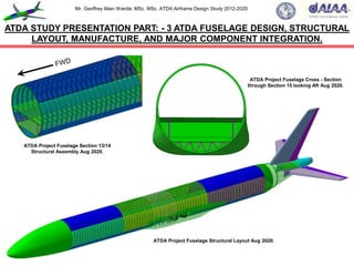
  • 1. Mr. Geoffrey Allen Wardle. MSc. MSc. ATDA Airframe Design Study 2012-2020 ATDA STUDY PRESENTATION PART: - 3 ATDA FUSELAGE DESIGN, STRUCTURAL LAYOUT, MANUFACTURE, AND MAJOR COMPONENT INTEGRATION. ATDA Project Fuselage Structural Layout Aug 2020. ATDA Project Fuselage Section 13/14 Structural Assembly Aug 2020. ATDA Project Fuselage Cross - Section through Section 15 looking Aft Aug 2020.
  • 2. Mr. Geoffrey Allen Wardle. MSc. MSc. ATDA Airframe Design Study 2012-2020 This presentation has been created, for the sole purpose of private study and is not the work of a company or government organisation it entirely the work of the author using resources in the public domain. The final paper will be submitted for peer - review to the American Institute of Aeronautics and Astronautics, Design Engineering Technical Committee, and the RAeS Structures and Materials Group, for pre submission assessment. Readers must be aware that the work contained may not be necessarily 100% correct, and caution should be exercised if this project or the data it contains is being used for future work. If in doubt, please refer to the AIAA, Design Engineering Technical Committee and the author. All of the views and material contained within this document are the sole research of the author and are not meant to directly imply the intentions of the Boeing Company, Airbus Group, GKN Aerospace, or any contractor thereof, or any third party at this date. Although the USAF and NASA have awarded contracts for studies into stitched composite transport aircraft structures, this work is not the product of their results or any part of their body of research, and should not be considered as such. This document contains no material what so ever generated or conceived by myself or others during my employment with BAE SYSTEMS (PLC), or that is governed by ITAR restrictions. This work is solely my own creation and is based on my own academic studies and literature research and the distribution of all information contained within this document is unlimited public release and has been approved through the AIAA. This document and any part thereof cannot be reproduced by any means in any format or used for any other research project without consultation with AIAA Design Engineering Technical Committee or the author. 2 Presentation “Health” Warning. .
  • 3. Mr. Geoffrey Allen Wardle. MSc. MSc. ATDA Airframe Design Study 2012-2020 3 This is an overview covering my current private design trade studies into the incorporation of new structural technologies and manufacturing processes into a future transport airframe design, and the incorporation of mission adaptive wing (MAW) technology for per review through the AIAA This study has been undertaken after my 13 years at BAE SYSTEMS MA&I, in airframe design development as a Senior Design Engineer, and my Cranfield University MSc in Aircraft Engineering completed in 2007(part-time), and was commenced in 2012 and I aim to complete it at the end of 2020. This utilises knowledge and skills bases developed throughout my career in aerospace, academic studies and new research material I have studied, to produce a report and paper exploring the limits to which an airframe research project can be perused using a virtual tool set, and how the results can be presented for future research and manufacturing. The toolsets used are Catia V5.R20 for design / analysis / kinematics / manufacturing simulation: PATRAN / NASTRAN for analysis of composite structures: AeroDYNAMIC™ for analysis of aircraft OML / Structural Loads / performance. This work will also form the basis for a PhD study, it is the product of my own research, and has not in any part been produced or conceptualised during my employment with BAE SYSTEMS or any company which is any part thereof. About this presentation:- This presentation is Part 3 of a series of 5 presentation Parts which cover the airframe major structural component development and engine and landing gear integration, and assembly manufacturing technologies. The contents of this presentation are given in the following slide. Overview of my current research activities in aircraft design for the ATDA paper.
  • 4. Mr. Geoffrey Allen Wardle. MSc. MSc. ATDA Airframe Design Study 2012-2020  Section 1:- ATDA Overview and fuselage configuration options and manufacturing, selection:  Section 2:- Structural loading, layout fuselage structural members and manufacturing:  Section 3:- The integration of the wing into the fuselage wing carry through box:  Section 4:- The integration of the empennage into the fuselage:  Section 5:- The integration of the nose and main landing gear into the fuselage:  Section 6:- The wing to fuselage belly fairing design (in work):  Section 7:- The horizontal tail to fuselage interface and seal configuration (in work):  Section 8:- Empennage flight control system device mechanical integration:  Section 9:- Fuselage assembly automation (in work). THIS WORK MAY NOT BE REPRODUCED WITHOUT EXPRESS PERMISSION OF MYSELF, and RAeS. 4 Table of contents of this ATDA Study Presentation Part 2.
  • 5. Mr. Geoffrey Allen Wardle. MSc. MSc. ATDA Airframe Design Study 2012-2020 Currently I am conducting a conceptual design research into the application the Future Integrated Structure (FIS) technology PRSEUS (using NASA/TM-2009-215955 (ref 1) and NASA/CR-2011- 216880 (ref 2), as my starting point) and mission adaptive flight control surfaces, to future large transport aircraft, as detailed in charts 1 to 6, chart 7 shows the projected baseline operational profile used in loads and fuel tank sizing calculations. This is a technical report for per review through the AIAA, future PRSEUS studies and the work breakdowns are shown in charts 8,9,10. The reference baseline aircraft selected is for a CFC twin engine 250-300 seat class aircraft design of conventional configuration. Table 1 presents design data and figures 1(a)/(b) illustrate the configuration of the Baseline ATDA aircraft, and figure 2 shows the supercritical airfoil selected the ATDA aircraft. This conventional design using the current materials technology shown in figure 2, and will be compared with an improved baseline design incorporating PRSEUS (FIS) technology figures 5, 6, 7 and 8, and Mission Adaptive Wing MAW Control surfaces, figures 9 and 10, to be designed using Catia V5.R20, to determine the structural / weight / and aerodynamic benefits at the trade study level and finally more advanced aircraft design configurations will be used to determine future potential applications. The study consists of three phases:- (1) The overall airframe configuration design and parametric analysis using both classical analysis and the Jet306 / AeroDYNAMIC V2.08 analysis tool set based on my Cranfield MSc: (2) The second is major structural wing component layout of the airframe initial structure with preliminary systems integration, and using Cranfield University methods and Catia V5.R20 GSA for structural sizing. (3) The final design study for both versions of the wing reference and new build will consist of parametric analysis, initial optimisation and structural layout and analysis and constitutes a feasibility study proposal to determine the benefits, and constraints on such an application. Section 1:- ATDA Overview, fuselage configuration options and selection. 5
  • 6. Mr. Geoffrey Allen Wardle. MSc. MSc. ATDA Airframe Design Study 2012-2020 IMPERIAL DATA. METRIC DATA. Wing Span (ft / in) 231 / 3.3 Wing Span (m) 70.52 Length (ft / in) 240/88 Length (m) 75.88 Wing Area (sq ft) 4,375.49 Wing Area (sq m) 406.481 Fuselage diameter (in) 235.83 Fuselage diameter (m) 5.99 Wing sweep angle 35° Wing sweep angle 35° Fuselage Length (ft /in) 244 / 3.8 Fuselage Length 74.47 Engine number / type 2 X RR Trent XWB Engine number / type 2 X RR Trent XWB T-O thrust (lb) 83,000 T-O thrust (kN) 369.0 Max weight (lb) 590,829 Max weight (tonnes) 268.9 Max Landing (lb) 451,940 Max Landing (tonnes) 205.0 Max speed (mph) 391 Max speed (km/h) 630 Mach No 0.89 Mach No 0.89 Range at OWE (miles) 9,631 Range at OWE (km) 15,500 Cruise Altitude (ft) 45,000 Cruise Altitude (m) 13,716 6 Table 1(a):- Initial Configuration Aircraft Data for the baseline ATDA study.
  • 7. Mr. Geoffrey Allen Wardle. MSc. MSc. ATDA Airframe Design Study 2012-2020 Figure 1(a):- Overall configuration and dimensions of the ATDA baseline aircraft. 7 70.52m (231ft 3.3in) Code F 18.34m (60ft 7in) 11.51m (37ft 1.6in) 30.58m (100ft 3.8in) O/A 75.87m (248ft 1.3in) Code E 74.47m (244ft 3.8in) 34.45m (113ft 2.4in) O/A 75.27m (246ft 10.7in) Fuselage sized for twin aisle 9 abreast 2 LD-3 containers 5.99m (235.85in) Section on ‘A’ ‘A’ ‘A’ 17.85m (58ft 4.6in) 11.92m (39.136ft) 7.771m 14.154m 17.248m For all analysis measurements see Section 14
  • 8. Mr. Geoffrey Allen Wardle. MSc. MSc. ATDA Airframe Design Study 2012-2020 Figure 1(b):- ATDA Configuration C of G, Tip back, and Overturn angles. 8 11.51m (37ft 1.6in) 75.87m (248ft 1.3in) Code E 74.47m (244ft 3.8in) 34.45m (113ft 2.4in) 17.85m (58ft 4.6in) Aft C of G 36.787m C of G 36.089m Fwd C of G 36.089m Fwd C of G 36.089m Aft C of G 36.787m 43° 57° 10° NLG MLG 75° From analysis of the Catia Concept model Tip back angle = 10°: Overturn angle = 75°
  • 9. Mr. Geoffrey Allen Wardle. MSc. MSc. ATDA Airframe Design Study 2012-2020 The ATDA Fuselage Baseline will use the skin panel structural layout of the Airbus A350 as the initial structural starting point as the longitudinal joints participate in the fuselages bending resistance and therefore imparts superior bending strength, and each panel can be optimised for its specific design case as shown in figure 67(a), these panels being as long as practical to minimise the number of circumferential joints. Although this is a more complex manufacturing option than the Boeing 787 barrel option which allows a single process to be used throughout, as shown in figure 67(b). The Airbus system offers greater compatibility with ATDA Prime fuselage PRSEUS stitched stringer manufacturing technology, although the noes and tail are barrel sections, shown in figure 67(c), figures 67(d)(e) shows cabin window sizing, location and planned capacity. The ATDA Fuselage Baseline frame stations and build joints are shown in figure 68(a):- Section 11/12 to Section 13/14 joint is at Frame 21: Section 13/14 to Section 15 joint is at Frame 41: Section 15 to Section 16/18 is at Frame 71: Section 16/18 to Section 19 join is at Frame 93: and the Section 19 to Section 19.1 joint is at Frame 106. The build joint philosophy selected for the ATDA Fuselage Baseline was the Airbus style lap joint with a splice strip located on frames, as shown in figure 68(d). This was adopted in preference to the Boeing butt joint with splice strap located between frames as shown in figure 68(c) which although easier to inspect and maintain but was not seen to enable the direct coupling for high loads that Airbus style lap joint ensures. The ATDA Fuselage frame design concept adopted the Boeing full depth bolted frames but with an I – section, mounted over co-bonded hat stringers as shown in figure 68(e) and stitched to the skin, this offered lower complexity and weight over the Airbus clip based philosophy. The ATDA Fuselage Prime, with full depth frames over stitched stringers. Table 8 gives a comparison of frame and stringer types and pitches from which the ATDA baseline values were derived. 9 Section 1:- ATDA Overview, fuselage configuration options and selection (cont.)
  • 10. Mr. Geoffrey Allen Wardle. MSc. MSc. ATDA Airframe Design Study 2012-2020 10 Figure 2:- Advanced Technology Demonstrator Aircraft “Tube and Wing” 2030. Composite Wings and Empennage applied PRSEUS stitched composite technology. All electric control system with MAW technology and advanced EHA actuation system. Hybrid Laminar Flow Control on wing upper surface. Composite Fuselage applied PRSEUS stitched composite stringers. Natural Laminar Flow on nacelles. Advanced Engines. Variable Trailing Edge Camber. Wing aspect ratio >10. Riblets on fuselage. Hybrid Laminar Flow Control on Vertical and Horizontal tails . SOFC/GT Hybrid APU. Positive control winglets. HT Thermoplastic composite engine pylons. Thermoplastic composite fuselage frames. Thermoplastic composite Belly Fairing.
  • 11. Mr. Geoffrey Allen Wardle. MSc. MSc. ATDA Airframe Design Study 2012-2020 11 PRSEUS stitched composite technology empennage 2016-2019. PRSEUS stitched composite technology wing 2013-2019. Automated Assembly of wing structure 2016-2020. Thermoplastic composite fuselage frames 2017-2018. Positive control winglets 2016-2020. Composite Fuselage applied PRSEUS stitched composite stringers 2017-2018. Thermoplastic composite Belly Fairing 2017-2019. H Temp Thermoplastic composite engine pylons proposed 2016-2018. Figure 3:- My Advanced Technology Demonstrator Aircraft Project Work Breakdown. Wing Carry Trough Box Structure defined and sized ( section 7). Wing Torsion Box Structure defined and sized (section 7).
  • 12. Mr. Geoffrey Allen Wardle. MSc. MSc. ATDA Airframe Design Study 2012-2020 12 Figure 4:- ATDA Fuselage design build philosophy selected and panel sizing. Analysis will be of Section 15 Panels initially. (*Note Port and Stbd side panel dimensions are identical). Fwd CFC Barrel Section (B787 example). Aft CFC Barrel Section (A350 example). Section 15 CFC Keel Panel (A350 example). Section 13/14 Crown panel:- Area = 68.051m²: Length = 12.792m Section 15 Crown panel:- Area = 110.074m²: Length = 20.645m Section 16/18 Crown panel:- Area = 74.569m²: Length = 14.391m Port Section 13/14 Side panel:- Area = 39.176m²: Length = 12.792m Port Section 15 Side panel:- Area = 63.635m²: Length = 20.645m Port Section 16/18 Side panel:- Area = 47.865m²: Length = 14.391m Section 13/14 Keel panel:- Area = 87.734m²: Length = 12.792m Section 15 Keel panel:- Area = 92.423m²: Length = 20.645m Section 16/18 Keel panel:- Area = 94.923m²: Length = 14.391m AIRBUS:- A350 XWB Boeing:- B787 AIRBUS:- A350 XWB
  • 13. Mr. Geoffrey Allen Wardle. MSc. MSc. ATDA Airframe Design Study 2012-2020 13 Figure 5:- ATDA Fuselage cabin window line cargo bay sizing and spacing. Window C/L 1,750mm above cabin floor top surface OML. Clearance = 5cm Clearance = 7.62cm 1.62m 1.87m LD3 Container. VIEW LOOKING AFT. Planned Passenger capacity 320:- 48 in Business class 6 abreast (8 rows) and 272 in Economy class 9 abreast (30 rows). Planned cargo capacity 36 standard LD3 containers, or 11 Pallets. The proposed fuselage PRSEUS and thermoplastic application design and structural development will use Airbus composite fuselage structural design philosophy with a Boeing style CFC barrel cabin / nose section, and a CFC barrel tail section. Composite Fuselage skins with PRSEUS stitched composite stringers. Monolithic back to back C- section Thermoplastic resin composite fuselage frames.
  • 14. Mr. Geoffrey Allen Wardle. MSc. MSc. ATDA Airframe Design Study 2012-2020 Overall loading on lifting surfaces:- Figure 15 illustrates the symmetrical flight case forces and moments to be considered in wing structural design. The structural role of the wing includes the following (ref 4):-  The transmission of lift the force, which is balanced at the root by the air loads on the fuselage and the stabilizer and by the inertial loads:  The collection of the chord-wise air loads and the loads from control surfaces and high-lift device hinges and the transfer of them to the main span-wise beam structure, which has to be achieved by a series of chord-wise beams and gives rise to a torque on the span-wise structure as well as contributing to the span-wise bending of the wing:  The transfer to the main beam of the local inertia loads from the wing mounted powerplants, and retracted main landing gear units:  The reaction of landing loads from the main landing gear units:  The pressure and inertia loads from integral fuel tanks and fuel:  The provision of adequate torsional stiffness of the wing in order to satisfy the aeroelastic requirements:  The reaction of wing and landing gear drag loads and possibly, thrust loads in the plane of the wing. Figure 15 illustrates aircraft loading and considerations: Figures 16(a) through (c) illustrate Symmetric:- span-wise, chord-wise, and fuselage loading. Figures 17(a) through (d) illustrate Asymmetric (roll):- span-wise, fuselage torque, and fuselage sideslip and yaw loading, and figure 18(a) (b)and (c) illustrate overall ground and fuselage loading. 14 Section 4:- Overall loading on the aircraft primary structures.
  • 15. Mr. Geoffrey Allen Wardle. MSc. MSc. ATDA Airframe Design Study 2012-2020 15 Figure 15(a):- Aircraft Structural Considerations. Different Objectives - Different Configurations - Similar Process.  RPV:-  Long range:  Loiter XX hours with out refuelling.  Military Fighter / Attack: -  Combat air and strike: ‫ח‬Z = 7.5g  Passenger transport:-  350 passengers:  50 year service life:  All weather:  High reliability:  Low maintenance:  Damage tolerant. Criteria: Requirements: Objectives:  FAR’s:  Mil specs:  SOW/PDS. External Loads Environment:-  Pressure:  Inertial:  Thermal:  Acoustic. Configuration  Internal loads:  Load paths. Analysis Sizing. Methods: Tests: Allowables Certification reports
  • 16. Mr. Geoffrey Allen Wardle. MSc. MSc. ATDA Airframe Design Study 2012-2020 Aircraft Structural Loads, Conditions, and Requirements. Flight Loads:- Ground Loads: Other loads and Conditions: Specific considerations are defined per:- CFR14 Parts 23 and 25 …….(FAR) CS-25 Book 1: SUBPART’s C and D Both for commercial aircraft (CFR14 Subpart C = structures). 16 Overall loading on the aircraft primary structures (continued).  Manoeuver  Gust  Control deflection  Buffet  Inertia  Vibration.  Vertical load factor  Breaking  Bumps  Turns  Aborted take-off  Spin - up  Spring back  One wheel / two wheel  Towing  Ground winds  Break away.  Jacking  Pressurisation  Crash  Actuation  Bird strike  Lightning strike  Hail  Power plant  Thermal  Fatigue  Damage tolerance  Fail safety  Acoustic  Ground handling.
  • 17. Mr. Geoffrey Allen Wardle. MSc. MSc. ATDA Airframe Design Study 2012-2020 17 Figure 15(b):- Aircraft Structural Loads, Conditions and Requirements. Typical commercial airliner critical static loads and conditions. Gust. Cabin Pressure. Negative manoeuvre and breaking. Positive manoeuvre and static gusts. Positive dynamic gusts. Aileron roll. Negative manoeuvre. Rudder kick: Yaw manoeuvre: Lateral gust. Buffet. Positive checked manoeuvre. Negative checked manoeuvre. Lateral manoeuvre. Taxi. Negative gusts. Engine blade out. N.B. Different load conditions are critical for different area.
  • 18. Mr. Geoffrey Allen Wardle. MSc. MSc. ATDA Airframe Design Study 2012-2020 18 Figure 15(c):- Overall loading on the aircraft wing surfaces. Lw Dw Lc T R S D Wing inertias (structural / fuel) – relieve all vertical and in-plane effects. Main landing gear. R= Vertical – wing vertical shear, moment, torque. D= Drag – wing in-plane shear, moment, torque. S= Side – wing vertical moment. Lw= Wing lift – wing vertical shear, moment, torque. Lc= Control /high-lift devices – wing vertical shear, moment, torque. Dw= Wing drag – wing in –plane shear, moment. T = Thrust – wing in – plane shear, moment, torque.
  • 19. Mr. Geoffrey Allen Wardle. MSc. MSc. ATDA Airframe Design Study 2012-2020 Symmetric flight cases:- Figure 16(a) illustrates the loading and corresponding form of the shear force diagram across the wing of a twin engined low wing commercial airliner configuration similar to the baseline study aircraft. Symmetric wing lift is relieved by the inertia of the structure, engines, systems and fuel (see section 6). The overall loading on the wing is reacted at the side of the fuselage at the wing root joint, and the bending moment is constant across the fuselage. The loads on a typical chord-wise wing section are illustrated in figure 16(b), the sum of the moments of the forces about a given chord-wise reference point yields the torque at that section, and the integration of the local values of the torque across the span of the wing yields the overall torque diagram. Finally figure 16(c) illustrates the loading and the basic form of the shear force diagram along the length of the fuselage of a twin engined low wing commercial airliner similar to the baseline study aircraft. The shear force and bending moment due to the horizontal air-load are relived along the fuselage by the transitional and rotational inertia effects. The net fuselage bending moment at the fore and aft centre of gravity (c.g.) position is balanced by the sum of the wing torques at the sides of the fuselage. Asymmetric flight case:- The asymmetric flight cases are more complex than the symmetric cases. A simplified example is the instantaneous application of aileron control on a wing having no initial lift results in an asymmetric loading case, although in practice there is no true symmetry between the up-rising and down-lowering ailerons. A more usual case is when the ailerons are applied as the aircraft is in steady level flight as shown in figure 17(a). 19 Overall loading on the aircraft primary structures (continued).
  • 20. Mr. Geoffrey Allen Wardle. MSc. MSc. ATDA Airframe Design Study 2012-2020 Figure 16(a):- Symmetric span – wise loading steady level flight condition. 20 Horizontal stabilizer load. Span-wise airload. Net distributed span-wise load. Fuselage reactions. Powerplant inertia. Powerplant inertia. Span-wise inertia load. Span-wise inertia load. SHEAR FORCE DIAGRAM.
  • 21. Mr. Geoffrey Allen Wardle. MSc. MSc. ATDA Airframe Design Study 2012-2020 21 Powerplant weight. Thrust -T Aerodynamic moment - M Control / Flap moment. Aerodynamic Lift - L Aerodynamic Drag - D Control Force. Control surface drag. Wing structural systems and fuel weight. Figure 16(b):- Symmetric loading chord – wise torques on the aircraft wing.
  • 22. Mr. Geoffrey Allen Wardle. MSc. MSc. ATDA Airframe Design Study 2012-2020 22 Figure 16(c):- Symmetric flight case fuselage loading. Thrust. Drag. Horizontal stabilizer airload. Aerodynamic moment from wing. Wing lift. Fuselage lift. Centre of gravity. Fuselage reaction. Aircraft inertia. Fuselage reaction Stabilizer load SHEAR FORCE DIAGRAM. Idealizing the fuselage as a loaded beam under shear loading.
  • 23. Mr. Geoffrey Allen Wardle. MSc. MSc. ATDA Airframe Design Study 2012-2020 Asymmetric flight case (continued):- The initial steady level flight condition will have a symmetric loading as shown in figure 16(a). The aileron and the consequent roll effects are approximately anti- symmetric in form figure 17(a). Figure 17(b) shows the shear force distribution due to this anti- symmetric condition as well as the overall result of combining it with the symmetric diagram. In a general rolling motion the couple resulting from the application of the aileron is balanced both by the acceleration effect of the roll inertia and the aerodynamic effect due to the rate of roll (ref:-4). The torque loading on the rear fuselage as a consequence of the application of the rudder control to cause a sideslip motion is shown in figure 17(c). The torque due to the fin side load is increased by the effect of asymmetric distribution of the trimming load on the horizontal stabilizer. Figure 17(d) shows the plan view of the fuselage, illustrating how the fin side load is reacted by side forces along the fuselage. The lateral bending along the fuselage is relived by sideslip and yaw inertial effects and the net value at the wing root is balanced by wing aerodynamic forces and yaw inertia. The torque on the fuselage is mainly reacted by the rolling inertia of the wing group. Fuselage cyclic pressure loading is also very important and is considered in fuselage loadings later in this study. Ground loading cases:- The ground loading cases unlike the flight cases occur from local ground forces. The take - off case is effectively a static balance of the aircraft weight by the vertical loads on the nose – and main – wheels. However, the landing cases are not static in that even after the wheels have made contact with the ground there is a translational motion of the centre of gravity of the aircraft, as well as a rotation in pitch and, possibly, roll. It is also usual for the wing to be providing lift at the time of wheel contact with the runway. Figures 18(a) and (b) illustrate the nature of the landing gear span-wise loading, and the longitudinal loading. Overall loading on the aircraft primary structures (continued). 23
  • 24. Mr. Geoffrey Allen Wardle. MSc. MSc. ATDA Airframe Design Study 2012-2020 24 Figure 17(a):- Asymmetric (roll) span – wise loading flight condition. Force due to aileron application. Net wing load in steady level flight. Load due to rate of rotation in roll (roll damping). Fuselage reactions – balance net vertical force and rolling moment. Resultant force and moment at fuselage Net moment is the difference of aileron, roll rate, and inertia effects. Force due to aileron application.
  • 25. Mr. Geoffrey Allen Wardle. MSc. MSc. ATDA Airframe Design Study 2012-2020 25 Figure 17(b):- Asymmetric (roll) span – wise loading flight condition shear force diagrams. Aircraft C/L Powerplant inertia. Anti-symmetric load. Aircraft C/L Fuselage reaction. Overall.
  • 26. Mr. Geoffrey Allen Wardle. MSc. MSc. ATDA Airframe Design Study 2012-2020 26 Reacting fuselage side load (balanced by inertia and wing-body air-load. Fin side load. Asymmetrical trim load on horizontal tail. Reacting fuselage torque (balanced mainly by wing rolling inertia. Aircraft C/L Figure 17(c):- Asymmetric loading flight condition fuselage torque.
  • 27. Mr. Geoffrey Allen Wardle. MSc. MSc. ATDA Airframe Design Study 2012-2020 27 Figure 17(d):- Loading on the fuselage (sideslip, yaw and pressure). Resultant side force – balanced by lateral (horizontal) inertia. Fuselage side air-load (distributed along fuselage length. Fin side load. Moment at centre of gravity due to side loads – balanced by yawing (rotational) inertia. Cabin Pressurisation creates cyclic hoop tensile stresses in the fuselage skin. P A A Section view on A
  • 28. Mr. Geoffrey Allen Wardle. MSc. MSc. ATDA Airframe Design Study 2012-2020 Ground loading cases (continued):- The various forces and moments are balanced in the same way as those arising in the flight cases, that is primarily by inertial effects. For this reason here the ground contact forces are regarded as applied loads rather than as reacting forces. Overall loading on the fuselage:- The loading determining the design of the fuselage is shown in figure 18(c). The roles of the fuselage includes the following:-  Provision of a pressurized (in commercial aircraft) envelope and structural support for the payload (passengers and freight) and crew. The skin thickness required to limit hoop tensile stresses to acceptable values is given by:- tp = ∆ρR / σρ Where:- ∆ρ is the maximum working differential pressure: R is the local radius of the shell : and σρ is the allowable tensile working stress.  To react landing gear, pressurization (in commercial aircraft), and powerplant loads when these items are located on, or within the fuselage, the nose gear being always present.  To transmit the control and trimming loads from the stabilizing / control surfaces to the centre of the aircraft, and to provide support and volume for equipment and systems. These requirements imply that to perform its structural role the fuselage has to be a longitudinal beam loaded both vertically and laterally, it also has to react torsion and local concentrated loads, the provision of a pressurized envelope implies a cylindrical encapsulated construction, with pressure bulkheads. Therefore a conventional commercial airliner fuselage of circular cross section, cabin floor, and cargo bay floor, with pressurized cabin, and external powerplants is the baseline ATDA airframe. 28 Overall loading on the aircraft primary structures (continued).
  • 29. Mr. Geoffrey Allen Wardle. MSc. MSc. ATDA Airframe Design Study 2012-2020 29 Figure 18(a):- Ground loading span – wise. S Ground vertical loads = R R R Ground side loads = S Resultant force and moment at fuselage. Net wing load. Fuselage reaction to balance vertical and side loads and rolling moment due to side load – balanced by roll, vertical and horizontal inertias.
  • 30. Mr. Geoffrey Allen Wardle. MSc. MSc. ATDA Airframe Design Study 2012-2020 30 Ground vertical loads = R R D Ground drag loads = D Fuselage vertical force – reacted by vertical (translational) inertia. Fuselage bending moment – reacted by pitch (rotational) inertia. Overall lift and weight in balance. Figure 18(b):- Ground loading longitudinal.
  • 31. Mr. Geoffrey Allen Wardle. MSc. MSc. ATDA Airframe Design Study 2012-2020 31 Figure 18(c):- Overall loading on the fuselage. LF LT D R S D R S Main landing gear. Nose landing gear. LF = Fin load – fuselage horizontal shear, moment, torque: LT = Tail load – fuselage vertical shear, moment, torque. R = Vertical - fuselage vertical shear moment: D = Drag – fuselage vertical shear moment: S = Side – fuselage horizontal shear, moment, torque. Cabin Pressurisation creates cyclic hoop tensile stresses in the fuselage skin. P
  • 32. Mr. Geoffrey Allen Wardle. MSc. MSc. ATDA Airframe Design Study 2012-2020 32 Figure 19(b):- Internal loads / Load Paths. Thrust. Drag. Horizontal stabilizer lift load. Aerodynamic moment from wing. Wing lift. Fuselage lift. Centre of gravity. Aircraft weight. Balance Load.  Considering all load conditions and requirements:  Developing a static load balance for each critical condition: This was done - Apply loads realistically; for local loads as - Determining where these loads are going to be balanced; well as for general  Cutting sections to determine local internal loads: vehicle loads.  Providing a path for the loads to follow (taking account that they follow the stiffest path):  Considering that most structural members perform more than one function. Getting the internal members to carry the airframe loads efficiently.
  • 33. Mr. Geoffrey Allen Wardle. MSc. MSc. ATDA Airframe Design Study 2012-2020 33 Figure 19(c):- Internal loading / load paths in the fuselage. Considering the fuselage acting as a beam. Bending moment is carried based on an Mc/I distribution. The Keel beam is added to restore the load path along the bottom of the fuselage removed when skin cutouts ware made for the wing carry through box and main landing gear. Lower longerons with effective skin carry compression axial loads due to bending moment. Skin carry shear load in - plane with VQ/I distribution. Crown skins and longerons carry tension loads due to bending moment. For a downward tail load the fuselage carries a shear and a bending moment.
  • 34. Mr. Geoffrey Allen Wardle. MSc. MSc. ATDA Airframe Design Study 2012-2020 34 Figure 19(d):- Design difference military use multiple longerons to bending. Figure 19(d)ii:- Commercial transport aircraft and freighters use skin stringers resist fuselage bending and have ring frames and pressure bulkheads. Figure 19(d)i:- F-22A Like all fighter aircraft use longerons to resist fuselage bending and have full section bulkhead and mate frames.
  • 35. Mr. Geoffrey Allen Wardle. MSc. MSc. ATDA Airframe Design Study 2012-2020 Table 3(b):- Materials Properties for FATA fuselage materials (Ref.22). Property. Unidirectional Tape /Slit Tape. Plain Weave Fabric. Thickness per ply 0.15mm 0.25mm Density (ρ) 1790kg/m 1570kg/m Longitudinal modulus E1 (GPa) 137.3 62.6 Transverse modulus E2 (GPa) 7.8 59.3 In-plain Shear modulus G12 (GPa) 5.23 4.6 Poisson's ratio V12 0.36 0.062 Longitudinal tensile strength F1t (MPa) 2057 621 Transverse tensile strength F2t (MPa) 46.9 594 Longitudinal compressive strength F1c (MPa) 1610 760 Transference compressive strength F2c (MPa) 207 707 In-plain shear strength F6 (MPa) 135 125 Standard Width ATL* 460mm / AFP* 12.5mm 1600 mm 35 *ATL= Automated Tape Laying : AFP = Automated Fibre Placement. 3 3
  • 36. Mr. Geoffrey Allen Wardle. MSc. MSc. ATDA Airframe Design Study 2012-2020 Category. Failure Mode. Weight Ratio (W2 / W1) 1 Tensile strength. ρ2 / ρ1 σe1/σe2 [kth1/ kth2 kθ1/kθ2] 2 Compressive strength. ρ2 /ρ1 σe1/σe2 [kch1/kch2 kθ1/kθ2] 3 Crippling ρ2 / ρ1 [Es1 σe1 / Es2 σe2] 4 Compression surface column and crippling ρ2/ρ1 [Es1 Et1 σe1/Es2 Et2 σe2] 5 Buckling compression and shear ρ2 /ρ1 [E1 / E2] 6 Aeroelastic stiffness ρ2/ρ1 E1/E2 7 Durability and damage tolerance ρ2/ρ1 [kd1kθ1/kd2kθ2] 36 Table 4:- Weight Ratio Equations for Various Failure Categories (based on Ref.6). 0.25 0.2 1/3
  • 37. Mr. Geoffrey Allen Wardle. MSc. MSc. ATDA Airframe Design Study 2012-2020 Material Code Weight Ratio (S1/S2) (ρ2/ρ1) Cat 1 Cat 2 Cat 3 Cat 5 Cat 6 Cat 7(a) Cat 7(b) Carbon / epoxy 3501/6QI 0.4 0.4 0.5 0.4 0.6 0.2 0.7 Carbon / epoxy 3501/6O 0.4 0.3 0.4 0.4 0.5 0.1 0.6 Titanium Ti6Al4V 0.5 0.5 1.1 1.0 1.0 0.8 0.5 Aluminium / Lithium 8090T3X 0.9 0.9 0.9 0.9 0.8 0.7 0.9 Aluminium alloy 7075 T76 0.7 0.7 0.9 0.9 1.0 0.7 0.7 Aluminium alloy 2024 T3 1.0 1.0 1.0 1.0 1.0 1.0 1.0 37 Table 5:- Weight Ratios for Airframe Materials for Various Failure Categories (Ref.6). n
  • 38. Mr. Geoffrey Allen Wardle. MSc. MSc. ATDA Airframe Design Study 2012-2020 Figure 31:- Woven Cloth Classifications and surface ply BVID protection options trades. 38
  • 39. Mr. Geoffrey Allen Wardle. MSc. MSc. ATDA Airframe Design Study 2012-2020 The ATDA Fuselage Baseline will use the skin panel structural layout of the Airbus A350 as the initial structural starting point as the longitudinal joints participate in the fuselages bending resistance and therefore imparts superior bending strength, and each panel can be optimised for its specific design case as shown in figure 67(a), these panels being as long as practical to minimise the number of circumferential joints. Although this is a more complex manufacturing option than the Boeing 787 barrel option which allows a single process to be used throughout, as shown in figure 67(b). The Airbus system offers greater compatibility with ATDA Prime fuselage PRSEUS stitched stringer manufacturing technology, although the noes and tail are barrel sections, shown in figure 67(c), figures 67(d)(e) shows cabin window sizing, location and planned capacity. The ATDA Fuselage Baseline frame stations and build joints are shown in figure 68(a):- Section 11/12 to Section 13/14 joint is at Frame 21: Section 13/14 to Section 15 joint is at Frame 41: Section 15 to Section 16/18 is at Frame 71: Section 16/18 to Section 19 join is at Frame 93: and the Section 19 to Section 19.1 joint is at Frame 106. The build joint philosophy selected for the ATDA Fuselage Baseline was the Airbus style lap joint with a splice strip located on frames, as shown in figure 68(d). This was adopted in preference to the Boeing butt joint with splice strap located between frames as shown in figure 68(c) which although easier to inspect and maintain but was not seen to enable the direct coupling for high loads that Airbus style lap joint ensures. The ATDA Fuselage frame design concept adopted the Boeing full depth bolted frames but with an I – section, mounted over co-bonded hat stringers as shown in figure 68(e) and stitched to the skin, this offered lower complexity and weight over the Airbus clip based philosophy. The ATDA Fuselage Prime, with full depth frames over stitched stringers. Table 8 gives a comparison of frame and stringer types and pitches from which the ATDA baseline values were derived. 39 Section 8:- The design and structural layout of the ATDA fuselage.
  • 40. Mr. Geoffrey Allen Wardle. MSc. MSc. ATDA Airframe Design Study 2012-2020 Figure 67(a):- Design philosophies for composite fuselages ( A350 XWB). 40 A350 Design philosophy:- In order to reduce the operating costs and environmental impact through reduced fuel burn the airbus A350 adopted the use of a four composite panel layout for the fuselage skins in the areas shown above. The key attributes of this layout:-  The skin panels are as long as possible to reduce the number of circumferential joints:  The longitudinal joints participate in the fuselage resistance to bending hence increasing bending strength:  Each panel can be optimised for its design case:  Significant weight reductions can be achieved by this design philosophy. 13m 20m 14m Side panels. Top panel. Keel panel. Port Side panel.
  • 41. Mr. Geoffrey Allen Wardle. MSc. MSc. ATDA Airframe Design Study 2012-2020 Figure 67(b):- Design philosophies for composite fuselages ( B-787). Contoured section. Constant section. Nose section. Section 48. Section 47. Section 46. Section 44 / 45. Section 43. Section 41. Fwd body joint. Aft body joint. Centre section joints. Aft section joint. Boeing 787 Design philosophy:- Multiple filament wound barrel sections with major circumferential splice joints between sections 41 to 43, and 46 to 47. These barrel sections allow a single manufacturing process to be applied to constant, contoured, and nose sections of the fuselage. Resitting hoop stresses better than metallics, this allows higher cabin pressures, and larger windows. 41
  • 42. Mr. Geoffrey Allen Wardle. MSc. MSc. ATDA Airframe Design Study 2012-2020 Figure 67(c):- ATDA Fuselage design showing frame stations and build joints. C21 C41 Section 11/12 C71 Section 13/14 C93 C106 Section 15 Section 16/18 Section 19 Section 19.1 FWD Fuselage Centre Fuselage AFT Fuselage Ground Line Radome. Nose Landing Gear. Frame 17 FWD Pressure Bulkhead (*Flat design).  Frame 17 Fwd Pressure Bulkhead being of Flat design, reacts the pressure loads in bending and will be machined from with a grid of vertical and horizontal support beams. FWD Body Mate Joint. FWD Centre Body Mate Joint. Wing Carry Through Box. AFT Centre Body Mate Joint. Main Landing Gear. Aft Body Mate Joint. Frame 96 AFT Pressure Bulkhead (*Curved Membrane design).  Frame 99 Aft Pressure Bulkhead being of Curved Membrane design, reacts the pressure loads in tension and will have radial and annular crack stoppers. These are lighter than the flat design, and provisionally a stitched CFC membrane similar to the A380 aft bulkhead is proposed. CFC Barrel section CFC Barrel section 4 CFC Panel section 4 CFC Panel section 4 CFC Panel section 42
  • 43. Mr. Geoffrey Allen Wardle. MSc. MSc. ATDA Airframe Design Study 2012-2020 Figure 67(d):- ATDA Fuselage cabin window showing sizing and spacing. 43 508mm 305mm 228mm Proposed cabin window size is 508mm high by 305mm wide viewing area, with a frame of 51mm. The proposed separation is 228mm and the fuselage skin thickness in the window band will increase to 4.0mm (based on revised analysis). 51mm 51mm Frame at 635mm pitch.
  • 44. Mr. Geoffrey Allen Wardle. MSc. MSc. ATDA Airframe Design Study 2012-2020 44 Figure 67(e):- ATDA Fuselage cabin window line cargo bay sizing and spacing. Window C/L 1,750mm above cabin floor top surface OML. Clearance = 5cm Clearance = 7.62cm 1.62m 1.87m LD3 Container. VIEW LOOKING AFT. Planned Passenger capacity 320:- 48 in Business class 6 abreast (8 rows) and 272 in Economy class 9 abreast (30 rows). Planned cargo capacity 36 standard LD3 containers, or 11 Pallets.
  • 45. Mr. Geoffrey Allen Wardle. MSc. MSc. ATDA Airframe Design Study 2012-2020 46 Figure 68(b):- ATDA Fuselage design showing structural layout. Note: - Section stringers (longerons) omitted from structural layout view for clarity. PRSEUS CFC Stringer Stitched to skin cleated to frame. Section 13/14 typical structural layout. CFC Cargo bay floor. CFC Cabin floor. CFC Cabin curved aft pressure bulkhead 120mm 100mm Ti alloy Wing attachment Frame C -section TYP. Ti Wing Carry through Box / Frame interface attachments. MLG Bay. 120mm 100mm Baseline CFC Ω - section Stringer co-bonded to skin. 101.6mm 38mm 38mm 38.6mm PRSEUS CFC I Frame C - section Stitched to skin and bolted to cabin internal structure TYP. 180mm 50mm CFC Cabin Frames I -section. CFC Cabin floor stanchions. CFC Cabin floor beams.
  • 46. Mr. Geoffrey Allen Wardle. MSc. MSc. ATDA Airframe Design Study 2012-2020 47 Figure 68(c):- ATDA Fuselage design showing internal loads / load Paths. The Frames provide reduced stringer column length. The Skins carry Shear, Torsion, and Tension loads . The Stringers carry Axial loads. d h For a Stringer system fuselage like the ATDA, d > h where d = Frame pitch and h = Stringer pitch. The Frames also support the passenger and cargo bay floor beams by reacting the end loads into the skins as shear. Seat rails run fore - aft and are supported by the floor beams. Floor beams tied to frames (react vertical loads) and to a longitudinal bam to react forward loads (landing and crash).
  • 47. Mr. Geoffrey Allen Wardle. MSc. MSc. ATDA Airframe Design Study 2012-2020 48 Figure 68(d):- ATDA Fuselage design showing internal loads / load Paths. For duel - lobe configurations, longitudinal beam (crease beam) and floor beams react out of plane loads at the lobe intersection. Fuselage skins carry external and cabin pressure load as a membrane.
  • 48. Mr. Geoffrey Allen Wardle. MSc. MSc. ATDA Airframe Design Study 2012-2020 49 Figure 68(c)(d):- ATDA Fuselage baseline build joint concept options (reference:-20). MID SECTION SKIN FWD SECTION SKIN SPLICE STRAP STRINGER SPLICE ANGLE SPLICE FILLER SPLICE C-CHANNEL Figure 68(c):- Example Butt-Joint with splice strap located between frames, therefore this type of build joint can be easily inspected and maintained. PANEL STRINGER BUTT-STRAP DOUBLER STRINGER COUPLING (U-SECTION) FRAME CLIP WITH STABILIZER ON STRINGER COUPLING FRAME CLIP ON BUTT-STRAP Z- CROSS SECTION FRAME Figure 68(d):- Example Lap-Joint with splice strap located on frames, enables direct coupling for high loads but is more of a challenge to inspect. Fwd Fuse Mid Fuse
  • 49. Mr. Geoffrey Allen Wardle. MSc. MSc. ATDA Airframe Design Study 2012-2020 50 Ω-Stringer Co-Bonded to Skin. Clip PPS Thermoplastic Matrix composite with quasi-isotopic layup Frame CFRP prepreg. 120mm Z- Frame lay up [30º/90º/-30º] with 0º reinforcement. 80mm Airbus A350 Co-Bonded CFC Ω-Stringers. Boeing 787 Co-cured CFC Hat-Stringers. Figure 68(e):- ATDA Fuselage baseline frame / stringer concept options (reference:- 20). Airbus A350 Bolted Z- Frame assembly. Boeing 787 Bolted Z-Frame assembly.
  • 50. Mr. Geoffrey Allen Wardle. MSc. MSc. ATDA Airframe Design Study 2012-2020 Considering the actual lay out of the ATDA fuselage baseline structure it is a combination of both Boeing and Airbus philosophies as described above. In the case of the Airbus A350 all of the fuselage panels (except the cockpit cabin see figures 2 and 67(a)) are CFC as are stringers, window frames, clips, and doors, with hybrid door frames structures consisting of CFC and titanium alloy. Depending on the location on the fuselage the stringers are either Ω (shown in figure 68(d) note extended flanges for frame clip attachment) or T profile and these are produced separately to the skin panels, and subsequently co-bonded on to the panels. As shown in figure 68(d) the frames are attached by a mixture of thermoplastic clips and special fasteners and are not bonded to the stringers or skin panels. Based on the difference in fuselage length between the A350-900 XWB and the A350-1000 XWB fuselages which is 7m and the reported difference in frame number of 11 frames the frame pitch can be estimated as 635mm. Also the CFC window frames are of L – section profile but have the same strength as the heavier traditional metal T - section frames (reference 20). From released photographs and presentations from Airbus (reference 8) the Ω-section stringer pitch is estimated at ~ 230mm. The Boeing 787 series are 50% CFC by airframe weight figure 2 shows the structural breakdown, as with the A350 the 787 fuselage has Titanium alloy / CFC hybrid door frames as shown in figure 30(b). The construction modules of the fuselage are complete barrel sections as shown in figures 67(b) and 68(d), and reportedly (reference 20) each barrel section contains 80 hat /Ω-section stringers, where the constant section is 5.46m (Airbus data) so the stringer pitch would be ~214mm. The average frame pitch on the B787 based on public data is between 574mm and 610mm and the latter figure is taken as the most representative. 51 The design and structural layout of the ATDA fuselage (continued).
  • 51. Mr. Geoffrey Allen Wardle. MSc. MSc. ATDA Airframe Design Study 2012-2020 52 Table 8:- Comparison of ATDA Fuselage frame / stringer layout with current aircraft. Aircraft type. Fuselage diameter (m) Skin material Frame material Frame profile Frame pitch (mm) Stringer material Stringer profile Stringer pitch (mm) A320 3.96 Aluminium alloy Aluminium Z 533 Aluminium Z ~150 A330 / A340 5.64 Aluminium alloy Aluminium Z 533 Aluminium Z ~220 A350 5.96 Composite Composite Z, L 635 Composite Ω, T ~230 A380 Width 7.14 Height 8.47 Aluminium Glare Aluminium J 635 Aluminium Z ~210 B737 3.76 Aluminium alloy Aluminium Z 508 Aluminium Ω 152-178 B747 6.40 Aluminium alloy Aluminium Z, C 508 Aluminium Ω, Z 203-254 B777 6.20 Aluminium alloy Aluminium Z 508 Aluminium Z ~230 B787 5.46 Composite Composite Z 610 Composite Ω ~214 ATDA Baseline 5.99 Composite Composite Z, L 635 Composite Ω, T 250
  • 52. Mr. Geoffrey Allen Wardle. MSc. MSc. ATDA Airframe Design Study 2012-2020 Based on the historical data in table 7 the ATDA fuselage structural layout, for analysis using AeroDYNAMIC™ and following data was used:- Materials:- By weight, 50% of the latest large commercial transports are CFC namely the A350 and B787 series, and the fuselage structure is predominantly CFC skin, stringers, and frames, with Titanium / CFC hybrid door frames. Previous Airbus and Boeing CS-25 fuselage structures have been metallic comprising of aluminium skins, frames, and stringers. The materials selected for the ATDA baseline fuselage was Cytec industries unidirectional tape X840 Z60 12K, and plain weave fabric X840 Z60 PW, for skin, frames, and stringers and the provisional thickness and ply layups are shown in Tables 8(a) through 8(c) the initial skin thickness was 2.9mm. Geometry:- Frame cross-sections have generally been Z-section or C-section (I-Section for ATDA) with a height of 85 - 100mm (ATDA 126mm), with a thickness of 2 - 3mm, and a flange width of 25mm (ATDA 50mm): Stringers have been Z-section with a height of 30mm, with a thickness of 2mm, and a flange width of approximately 15mm: CFC Omega - profile stringers (Baseline ATDA) current designs) have a height of 25 – 35mm, a thickness of 1.5 – 2.0mm, and a head width of 25mm and a flange width of 100 – 130mm: Skin thicknesses dependant on location is reported to be between 1.0mm and 2.6mm thick. Frame pitch from table 7 ranges 475.2 mm to 533.4mm with some extending this to 610mm to 635mm. A frame pitch of 635mm was selected for both ATDA baseline fuselage and the ATDA PRSEUS Prime fuselage for comparison with wide body composite fuselages. Stringer pitch ranges from 150mm to 254mm. A stringer pitch of 250mm was used for ATDA. The structural ply lay up tables for these components are given in table 9(a) through (c). 53 The design and structural layout of the ATDA fuselage (continued).
  • 53. Mr. Geoffrey Allen Wardle. MSc. MSc. ATDA Airframe Design Study 2012-2020 Structural Ply No Only. Material Nominal ply thickness (mm) Ply orientation 1 Fabric 0.25 0º/90º 2 UD 0.15 0º 3 UD 0.15 45º 4 UD 0.15 90º 5 UD 0.15 135º 6 UD 0.15 0º 7 UD 0.15 45º 8 UD 0.15 90º 9 UD 0.15 135º 10 UD 0.15 135º 11 UD 0.15 90º 12 UD 0.15 45º 13 UD 0.15 0º 14 UD 0.15 135º 15 UD 0.15 90º 16 UD 0.15 45º 17 UD 0.15 0º 18 Fabric 0.25 0º/90º 54 Table 9(a):- Initial proposed ATDA Fuselage 2.9mm thick skin ply stacking sequence.
  • 54. Mr. Geoffrey Allen Wardle. MSc. MSc. ATDA Airframe Design Study 2012-2020 55 Table 9(b):- Proposed ATDA Fuselage 2.6mm thick Ω-stringer ply stacking sequence. Structural Ply No Material Nominal ply thickness (mm) Ply orientation 1 Fabric 0.25 0º/90º 2 UD 0.15 0º 3 UD 0.15 45º 4 UD 0.15 135º 5 UD 0.15 90º 6 UD 0.15 45º 7 UD 0.15 135º 8 UD 0.15 0º 9 UD 0.15 0º 10 UD 0.15 135º 11 UD 0.15 45º 12 UD 0.15 90º 13 UD 0.15 135º 14 UD 0.15 45º 15 UD 0.15 0º 16 Fabric 0.25 0º/90º
  • 55. Mr. Geoffrey Allen Wardle. MSc. MSc. ATDA Airframe Design Study 2012-2020 56 Table 9(c):- Proposed ATDA Fuselage 3mm thick Z-frame ply stacking sequence. Structural Ply No Material Nominal ply thickness (mm) Ply orientation 1 Fabric 0.25 ±45º 2 Fabric 0.25 0º/90º 3 Fabric 0.25 ±45º 4 Fabric 0.25 0º/90º 5 Fabric 0.25 ±45º 6 Fabric 0.25 0º/90º 7 Fabric 0.25 0º/90º 8 Fabric 0.25 ±45º 9 Fabric 0.25 0º/90º 10 Fabric 0.25 ±45º 11 Fabric 0.25 0º/90º 12 Fabric 0.25 ±45º
  • 56. Mr. Geoffrey Allen Wardle. MSc. MSc. ATDA Airframe Design Study 2012-2020 Structural Ply No Only. Material Nominal ply thickness (mm) Ply orientation 1 Fabric 0.25 0º/90º 2 UD 0.15 0º 3 UD 0.15 45º 4 UD 0.15 90º 5 UD 0.15 135º 6 UD 0.15 0º 7 UD 0.15 45º 8 UD 0.15 90º 9 UD 0.15 135º 10 UD 0.15 135º 11 UD 0.15 90º 12 UD 0.15 45º 13 UD 0.15 0º 14 UD 0.15 45º 15 UD 0.15 90º 16 UD 0.15 135º 57 Table 9(d):-Fuselage window Band 4.0mm thick skin ply stacking sequence.  Continued on next slide full 25ply thickness.
  • 57. Mr. Geoffrey Allen Wardle. MSc. MSc. ATDA Airframe Design Study 2012-2020 58 Structural Ply No Only. Material Nominal ply thickness (mm) Ply orientation 17 UD 0.15 135º 18 UD 0.15 90º 19 UD 0.15 45º 20 UD 0.15 0º 21 UD 0.15 135º 22 UD 0.15 90º 23 UD 0.15 45º 24 UD 0.15 0º 25 Fabric 0.25 0º/90º Table 9(d):- Fuselage window Band 4.0mm thick skin ply stacking sequence (continued).  Continued from previous slide full 25ply thickness.
  • 58. Mr. Geoffrey Allen Wardle. MSc. MSc. ATDA Airframe Design Study 2012-2020 ATDA Baseline Vertical tail design. The vertical tail presents a set of design issues which are different from those of the wing, or horizontal tail and these are be itemised below:- a) It is not unusual for the vertical tail of a large transport to be integrally attached to (but still removable from) the rear fuselage, the leading and trailing edge spars of the vertical tail being attached to dedicated fuselage frames. A root integration plate is built into the vertical tail to coincide with the upper surface of the fuselage and is used to transmit the vertical tail root skin shear loads directly into the fuselage skin, this is the case with the Boeing 787 and 777 CFC vertical tails which use a tension fitting plate to interface with the fuselage with attachment to this plate at the VT torsion box leading and trailing edge spars. Vertical tail span-wise bending results in a fuselage torsion. In some cases it is logical to incline the rear spar bulkhead to continue the line of the rear spar of the vertical tail torsion box, as this is usually at the end of the fuselage well aft of the rear pressure bulkhead, although no current airliner produced by either Airbus or Boeing has adopted this layout. All of the current large Airbus and Boeing passenger aircraft, based on published data from literature surveys and examination of aircraft cutaways attaching the rear spar to perpendicular frames. The front spar and any intermediate attachments to frames are also made to perpendicular frame stations within the aft fuselage Section 19, with the transition being made at the Vertical Tail root rib or integration plate in the case of the B-777 , and B-787, shown in figure 69(a)ii The structural layout is generally the same format as the wing with front and rear spars and ribs forming the vertical tail torsion box, with additional rudder hinge ribs and auxiliary front spar to support de-icing equipment and other systems in the vertical tail leading edge fairing. 59 Section 9:- The design and structural layout of ATDA empennage.
  • 59. Mr. Geoffrey Allen Wardle. MSc. MSc. ATDA Airframe Design Study 2012-2020 60 Figure 69(a):- ATDA Vertical tail showing fuselage attachment design philosophy. Figure 69(a)i:- Airbus A350 XWB Vertical tail to fuselage attachment philosophy i.e. leading edge, trailing edge spar, and intermediate attachment lugs into fuselage clevis fittings (Flight International and Airbus gallery). Rudder is CFC and Nomex honeycomb skins with aluminium ribs. Figure 69(a)ii:- Boeing 777 and 787 Vertical tail to fuselage attachment philosophy i.e. Tension fixtures and integration plate (Flight International and Boeing gallery). Rubber is CFC and Nomex honeycomb skins with aluminium ribs.
  • 60. Mr. Geoffrey Allen Wardle. MSc. MSc. ATDA Airframe Design Study 2012-2020 b) Alternatively the vertical tail is designed to be readily detached as in the case of fighter aircraft and modern large transports, in this case attachment is through a system of lugs attached to the leading edge and trailing edge spars and intermediate lugs as shown for the Airbus A350 in figure 69(a)i. The vertical attachment lugs are arranged in both lateral and fore and aft directions so that in addition to vertical loads they react side and drag loads. The normal layout being that the lugs attached to the leading edge spar arranged laterally and react the vertical and drag loads, and the lugs attached to the trailing edge spar are arranged in the fore and aft direction and react the vertical and side loads. This lug attachment philosophy was selected for the ATDA vertical tail which is attached at the leading edge and trailing edge spars with lateral and fore and aft lugs to perpendicular fuselage frames. c) The rudder attachment to the vertical tail is invariably supported by a number of discrete hinges and number and location of these hinges depends on the length and weight of the rudder, and the other major points to consider in rudder attachment design are as follows:- i. The bending distortion of the control surface relative to the fixed vertical tail must be limited so that the nose of the control does not foul the fixed shroud: ii. The control hinge loads and the resulting shear forces and bending moments should be equalized as far as possible: iii. Structural failure of a single hinge should be tolerated unless each hinge is of fail-safe design and can tolerate cracking in one load path. 61 The design and structural layout of ATDA empennage (continued).
  • 61. Mr. Geoffrey Allen Wardle. MSc. MSc. ATDA Airframe Design Study 2012-2020 62 Figure 69(b):- ATDA Vertical tail showing internal structural layout key datum positions. Fwd Attachment Frame interface:- two lateral lugs the Leading Edge spar root. Aft Fuselage barrel section. Mid Attachment Frame interface:- two Fore and Aft lugs on the Mid spar root. Aft Attachment Frame interface:- two Fore and Aft lugs on the Trailing Edge spar root. Triplex rudder EHA actuators. CFC Stringers. CFC Leading Edge Spar. CFC Vertical Tail Leading Edge box with Al/Li Ribs. CFC Mid (Intermediate) Spar. CFC Trailing Edge Spar. Al/Li alloy all Ribs. Rudder CFC Honeycomb skins with Al/Li ribs . Figure 69(b)i:- VT / Frame interface. FWD Figure 69(b)ii:- VT internal layout Port skin and stringers removed. UP CFC Skins. Vertical Tail Pf Area = 35.36m² Rudder Pf Area = 15.00m²
  • 62. Mr. Geoffrey Allen Wardle. MSc. MSc. ATDA Airframe Design Study 2012-2020 These points suggest the use of a relatively large number of discrete hinges but there are issues associated with this solution. There is the obvious issues of high assembly complexity and maintenance, and hinge alignment difficulties. Additionally the loads likely to be induced in the rudder by the distortion under load of the vertical tail to which it is attached may be significant. These problems do not arise if only two hinge points are used as any span-wise distortion or misalignment can be accommodated by designing one of the hinges so that it can rotate about a vertical axis a so called „floating‟ hinge. When more than two hinges are used this „floating‟ hinge concept cannot fully overcome the problems. However it is possible to design the control surface so that it is flexible in bending and indeed the more hinges there are the easier this is to accomplish. One hinge must always be capable of reacting side loads in the plane of the control surface, the hinges being supported near to the aft extremities of the vertical tail ribs. For the initial internal structural layout concept the ATDA Baseline Vertical Tail the rudder attachment layout of the Airbus A330 was used as a starting point for analysis using AeroDYNAMIC™ of loads and detailed structural analysis. ATDA Baseline Horizontal tail design. When the horizontal tail is constructed as a single component across the centreline of the aircraft the basic structural requirements are the very similar to the wing see above. Therefore to address this the concept structure was designed as two spar multi rib torsion box, with two actuator positions for the elevator on the Port and Stbd Horizontal Tail Planes figure 70(b), this is similar to the Airbus A350 WXB, and A330. The Boeing 787 takes a different approach with the horizontal tail torsion box being multi spar construction. The all moving ATDA horizontal tail is attached to the fuselage by the fwd Screw Jack actuator fitting and aft pivot lugs figure 70(a). 63 The design and structural layout of ATDA empennage (continued).
  • 63. Mr. Geoffrey Allen Wardle. MSc. MSc. ATDA Airframe Design Study 2012-2020 64 Figure 70(a):- ATDA Horizontal tail showing internal and interface design philosophy. Figure 70(a):- Airbus A350 XWB Horizontal tail to fuselage attachment philosophy i.e. stiffened centre box is attached to the screw jack actuator at the front, and at trailing edge is attachment with two pivot outer lugs. The same basic layout is used by Boeing (Flight International and Airbus gallery). Elevators are constructed of CFC skinned Nomex honeycomb skin panels with aluminium ribs, and mesh instead of electrical bonding straps. Port Lug Stbd Lug HT Composite leading edge spars.
  • 64. Mr. Geoffrey Allen Wardle. MSc. MSc. ATDA Airframe Design Study 2012-2020 65 Jack Screw actuator attachment fitting Elevators CFC Honeycomb skins with Al/Li ribs HT pivot lugs Fixed CFC LE /TE spars CFC Torsion Box Skins CFC Ribs attached to Stitched Skin Cleats Al/Li Topologically Stiffened AM Ribs Al/Li Topologically Stiffened AM Ribs PRSEUS Skin Stringers Al/Li Machined Ribs Ti Ribs to Spar Cleats Ti Machined Removable LE Spar Ti Machined Removable Ribs Ti Machined Tip Rib Ti Machined Root Ribs FWD UP PORT Top cover skins, splices and stringers removed for clarity. Figure 70(b):- ATDA Horizontal tail showing internal structure key datum positions.
  • 65. Mr. Geoffrey Allen Wardle. MSc. MSc. ATDA Airframe Design Study 2012-2020 The landing gear loads and reactions are the largest local on the aircraft structure, and therefore transmitting such large local loads into the semi-monocoque structure of the wing box requires extensive local reinforcement. Since the landing gear loads are large, there can be severe weight penalties in the use of indeterminate structural load paths. An indeterminate structure is one in which a given load may be reacted by more than one load path with the distribution being subject to the relative total stiffness of these paths. In practice the manner in which the members share the load can be determined but only when the design is finalized, and often overlapping assumptions are made of the load paths which results in an over deigned heavy structure. Often the gear loads can be spread out so as to keep the local reinforcement to a minimum, in the case of the ATDA as with the A350 family of aircraft the use of carbon fibre reinforced plastic (CFRP) required a reduced point loading to reduce the amount of structural reinforcement required in the aft spar. So as shown in figures 77(a), 77(b) for ATDA a double side-stay landing gear was developed similar to the Messier-Dowty A350 configuration where the aft side-stay is attached to the auxiliary spar (or gear kick beam), thus reducing the reinforcement weight for the aft CFRP spar. The support structure in the wing is designed to higher loads than the gear itself to ensure that in the event of impact the gear will break off cleanly with the wing and not precipitate a fuel tank rupture. The installation of the landing gear aft of the wing carry through box is shown in figure 79(c) and the requirement is for a 4.1m fuselage bay. For this study the landing gear loads are developed using the methods in references 4 and 7. 66 Section 12:- Integration of baseline and developed aircraft nose and main landing gear.
  • 66. Mr. Geoffrey Allen Wardle. MSc. MSc. ATDA Airframe Design Study 2012-2020 67 Figure 77(a)/(b):- ATDA Nose and Main landing gear used in for the design study. Aft Stay Figure 77(a) Sized Nose landing gear general arrangement for integration in the ATDA Design Study. Figure 77(b) Sized Port Main landing gear general arrangement for integration in the ATDA Design Study. FWD FWD Fwd Stay Sliding piston Main Fitting Upper Torque Link Lower Torque Link Bogie Unit Attachment fore and aft pintle Upper Drag Stay Lower Drag Stay Main Fitting Steering Assembly Upper Torque Link Lower Torque Link Retraction Actuator Fwd Stay Lock Note:- Although Landing Gear Wheels and Struts have been sized these are not detail designs. Lateral pintle
  • 67. Mr. Geoffrey Allen Wardle. MSc. MSc. ATDA Airframe Design Study 2012-2020 68 Figure 77(c):- ATDA Main Landing Gear Installation checks in 4.43m bay. 4 wheel bogie MLG Installation check (view from below old WCB Keel configuration). FWD OUT BD UP UP OUT BD FWD 4 wheel bogie MLG installation Section 15 Keel panel kinematics clash check (view from below).
  • 68. Mr. Geoffrey Allen Wardle. MSc. MSc. ATDA Airframe Design Study 2012-2020 1) NASA/TM-2009-215955:-Experimental Behaviour of Fatigued Single Stiffener PRSEUS Specimens: by Dawn C. Jegley : NASA Langley Research Center: Dec 2009. 2) NASA/CR-2011-216880:-Damage Arresting Composites for Shaped Vehicles Phase II Final Report: by Alex Velicki et al: NASA Langley Research Center: Jan 2011. 3) Morphing Skins:- Paper No 3216: The Aeronautical Journal: by C. Thill et al: Bristol University: March 2008. 4) Aircraft Loading and Structural Layout: Professional Engineering Publishing: by Prof Denis Howe: 2004: ISBN 186058432 2. 5) Composite Airframe Structures: Conmilit Press Ltd Hong Kong: by Michael Chun-Yung Niu: 1992: ISBN 962-7128-06-6. 6) Composite Materials for Aircraft Structures second edition: AIAA Education Series: by Alan Baker et al: 2004: ISBN 1-56347-540-5. 7) Airframe Structural Design: Conmilit Press Ltd Hong Kong: by Michael Chun-Yung Nui: 1992: ISBN 962-7128-04X. 8) A350XWB Aircraft Configuration: Airbus presentation 2007: by Oliver Criou. 9) NASA Supercritical Airfoils:- NASA Technical Paper 2969: by Charles D. Harris: NASA Langley Research Center: 1990. 10) My Composite Design Capability Maintenance Studies: Private Study 2017: Mr. Geoffrey Wardle published on LinkedIn. 11) My Metallic Design Capability Maintenance Studies: Private Study 2017: Mr. Geoffrey Wardle published on LinkedIn. 69 Current reference material in use for the ATDA project for the AIAA list will be extended.
  • 69. Mr. Geoffrey Allen Wardle. MSc. MSc. ATDA Airframe Design Study 2012-2020 70 Current reference material in use for the ATDA project for the AIAA list will be extended. 12) NASA N+3 Subsonic Ultra Green Aircraft Research: by Marty Bradley (Principal Investigator Boeing Research and Technology) et al: Boeing Research & Technology: Published April 20th 2010. 13) Boeing 777x Airport Compatibility ECCN:9E991: by Boeing Airport Compatibility Engineers: Boeing Commercial Airplanes: Published July 2013. 14) Automated Assembly of Aircraft Structures: by Vorobyov. Yu. A. et al : Published by the National Aerospace University “KhAl”: Kh-Al – ERA Consortium 2013. 15) Technology and Innovation for Future Composite Manufacturing GKN Aerospace Presentation: by Ben Davies and Sophie Wendes. 16) ABB Robotics at www.abb.com/robotics for all product datasheets and surface models of the IRB4400/60 robot and the 6650S_90 robot. 17) Damage Tolerance in Aircraft:- by Prof P.E. Irving Damage Tolerance Group School of Engineering Cranfield University: Published by Cranfield University 2003 / 2004. 18) The Rapid estimation of span loading of swept wings: Cranfield College of Aeronautics Report No 32, 1951: by Stanton-Jones. 19) Fully controlled production environment for autoclave injection processes: LOCOMACHS Consortium: by M. Kleineberg et.al: Published 11/03/2015. 20) CODAMEIN Research Project EASA.2010.C13 Final Report 20120312: European Aviation Safety Agency: by Zoltan Mikulik and Peter Haase: Published 12/03/2012. 21) AMC 20-29, Composite Aircraft Structure, Annex II to ED Decision 2010/003/R of 19/07/2010.
  • 70. Mr. Geoffrey Allen Wardle. MSc. MSc. ATDA Airframe Design Study 2012-2020 71 22) Design and Analysis of a Composite Fuselage: 3rd CTA-DRL Workshop on Design Analysis and Flight Control September 14-16, 2009: S.J. Campos. SP, Brazil: by Marco Aurelio Rossi and Sergio Frascion Muller de Almdeida ITA Mechanical Engineering Department. 23) Certification Specifications For Large Aeroplanes CS-25 Amendment 3 2007: European Aviation Safety Agency: Annex to ED Decision 2007/010R. 24) The Jet Engine: Published on behalf of Rolls Royce Plc by John Wiley & Sons Ltd: 2015: ISBN 978-1- 119-06599-9. 25) IATA Technology Roadmap Technical Annex: by John Banbury IATA et.al. Taeyun. P. Choi Georgia Institute of Technology et.al. and Eike Stumpf DLR: Published by IATA October 2008: www.iata.org 26) Interdisciplinary Wing Design – Structural Aspects )3WAC-29: by Christian Anhalt, Hans Peter Monner, Elmar Breitbach: Published by German Aerospace Centre (DLR): Institute of Structural Mechanics. 2003. 27) Airbus the complete story: by Bill Gunston OBE: Published by Haynes Publishing ISBN 978 1 84425 585 6: 2009. 28) Boeing 787 Dreamliner: by Guy Norris and Mark Wagner: Published by Zenith Press ISBN 13: 978-0- 7603-2815-6: 2009. 29) Propulsion integration challenges - lecture to DGLR: by Airbus Hamburg 5th July 2007. Current reference material in use for the ATDA project for the AIAA list will be extended.