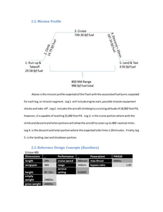
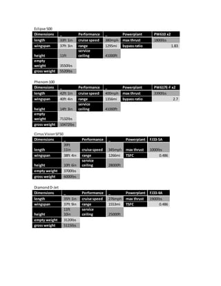
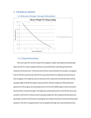
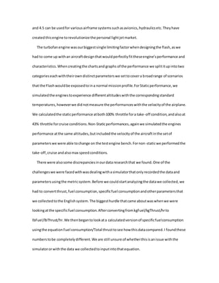
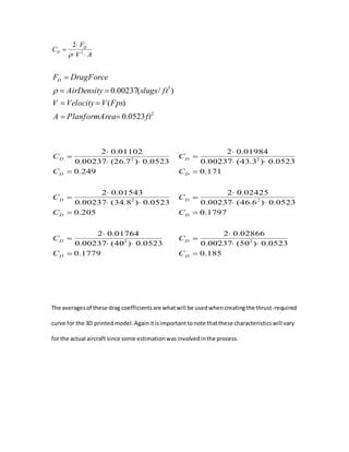
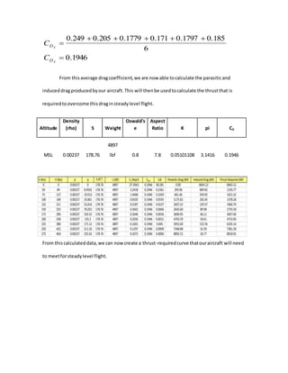
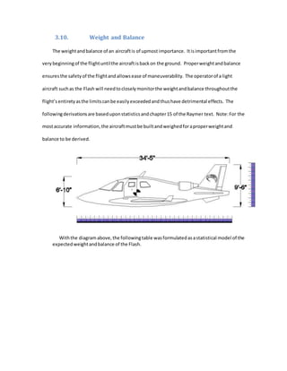
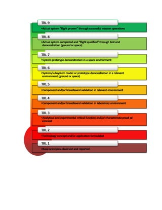
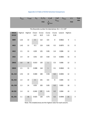
This document provides details of an aircraft design project for a new personal jet called "The Flash" being designed by Kent Aerospace. It includes sections on requirements analysis, technical design, manufacturing plan, regulatory compliance, program management, finance, marketing, and socioeconomic impacts. The technical design section provides details on sizing methodology, assumptions, wing and tail geometry, thrust-to-weight ratio, powerplant specifications, wing loading data, and performance results. The design utilizes twin DGEN 380 turbofan engines from Price Induction and is intended to carry 3 passengers up to 800 nautical miles at a cruise speed of 230 knots.


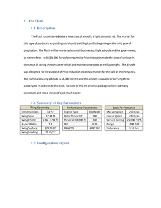
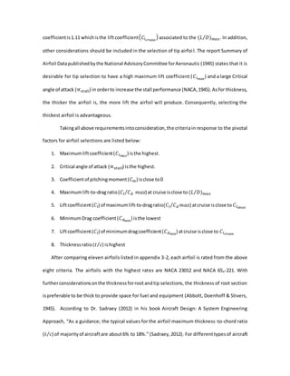
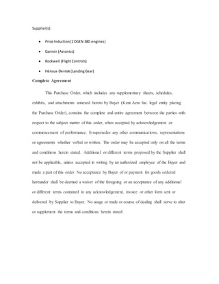
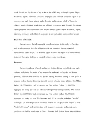
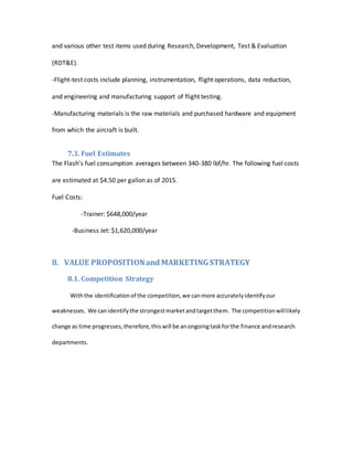
![individuallyandthe chosennumberstakenfromthose thatwere deemedmore accurate than
the rest.
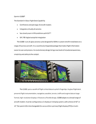
3.2.1. Design Space
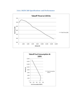
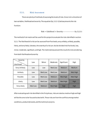
Since the aircraftwas designedaroundthe engines,we knew fromthe beginningwhatour
altitudesof operationwouldbe. Price Inductionhadalreadydeterminedthe enginestobe
operationallysounduptoan altitude of 25,000 feetPA. Consideringthe powerthe DGEN 380
produces,a lighterjetwasthe onlyviable option.
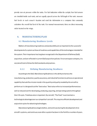
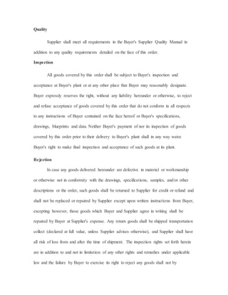
3.3. Assumptions
Major assumptionsaffectingthe design:
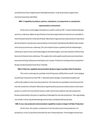
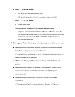
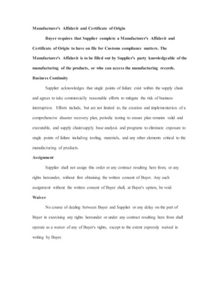
3.3.1. Assumptions Used for Lift-to-Drag Ratio (𝑳 𝑫⁄ )
𝐿
𝐷 𝑚𝑎𝑥
estimationconstant: 𝐾𝐿𝐷 =15.5 for civil Jets
Wettedarearatio: 𝑆 𝑤𝑒𝑡 𝑆 𝑟𝑒𝑓⁄ = 4.1
AspectRatio:AR= 7.8 for General Aviation-twinengine
3.3.2. Assumptions Used for Initial Sizing
Range:R = 800 [𝑚𝑛𝑖]
LoiterTime-Endurance:E= 20 [𝑚𝑖𝑛]
Cruise SpeedatFL180: 𝑀𝑐𝑟𝑢𝑖 𝑠 𝑒 = 𝑉𝑐𝑟𝑢𝑖𝑠𝑒 = 0.35 Mach
Constantinemptyweightfractionequation:A=1.51 for General aviation-twin engine
Constantinemptyweightfractionequation:C= -0.10 forGeneral aviation-twinengine
Variable sweptconstant: 𝐾𝑉𝑆 =1.00 forfixedsweep](https://image.slidesharecdn.com/253118ae-a5c9-40ed-ac48-410ea800dbaa-160802003508/85/Final-Report-Aircraft-Design-13-320.jpg)
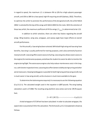
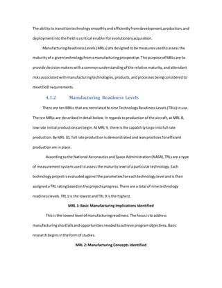
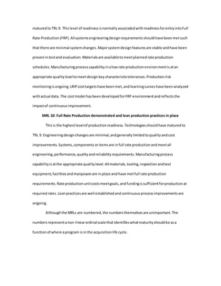
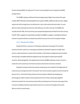
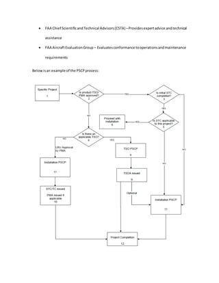
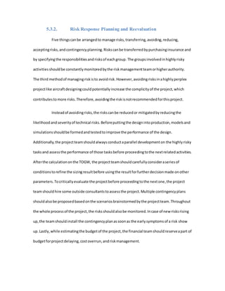
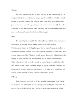
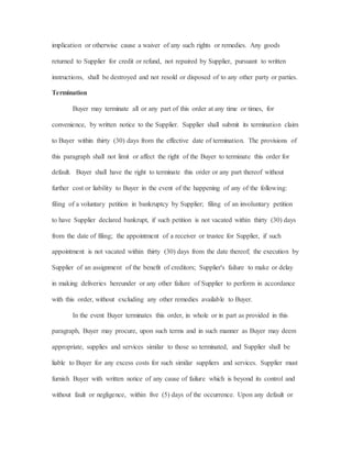
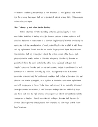
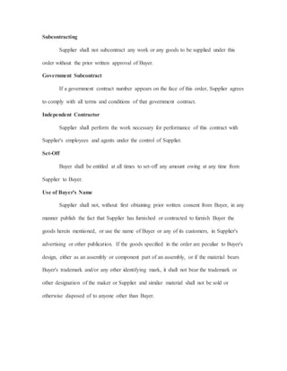
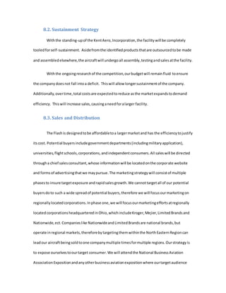
![3.3.3. Assumptions Used for Thrust-to-Weight Ratio (𝑻 𝑾⁄ )
Maximumspeed: 𝑀 𝑚𝑎𝑥 = 1.2 𝑀𝑐𝑟𝑢𝑖𝑠𝑒
ConstantinT/W statistical estimationequation:a=0.267 forJet Transport
Constantin T/W statistical estimationequation:C=0.363 forJet Transport
3.3.4. Assumptions Used for Wing Loading (𝑾 𝑺⁄ )
Take off distance: 𝑆 𝑡 𝑜⁄ = 2500 [𝑓𝑡]
Take off Parameter: TOP = 120
ApproachSpeed: 𝑉𝐴𝑃𝐻 = 120 [𝑓𝑡]
OswaldEfficiency:e = 0.8
Zero-Left-Dragcoefficient: 𝐶 𝐷0
= 0.015 for Jets
3.3.5. Assumptions Used for Wing, Tail, and Fuselage Geometry
Taper Ratioof wing: 𝜆 𝑤 = 0.25
ConstantinFuselage lengthequation:a= 0.67 for Jettransport
ConstantinFuselage lengthequation:c= 0.43 for Jettransport
Taper Ratioof tails: 𝜆ℎ= 𝜆 𝑣= 𝜆 𝑤 = 0.25
Aspectratioof horizontal tail: 𝐴𝑅ℎ =2 3⁄ 𝐴𝑅
Aspectratioof vertical tail: 𝐴𝑅 𝑣 = 1.5
Horizontal tail volume coefficient: 𝑐 𝐻𝑇 =0.90 fortwinturboprop](https://image.slidesharecdn.com/253118ae-a5c9-40ed-ac48-410ea800dbaa-160802003508/85/Final-Report-Aircraft-Design-14-320.jpg)
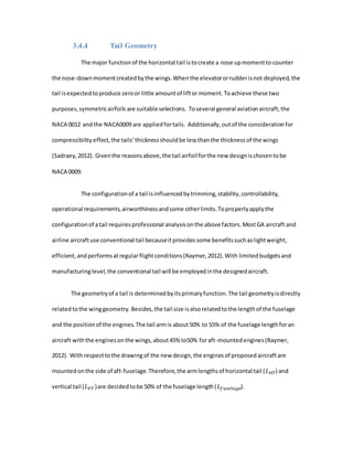
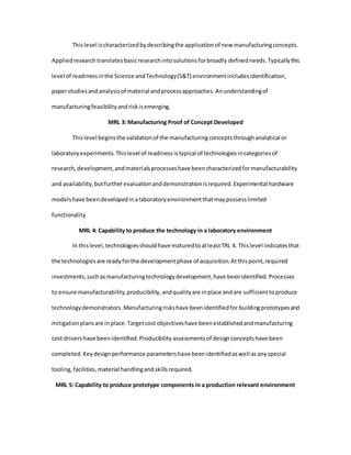
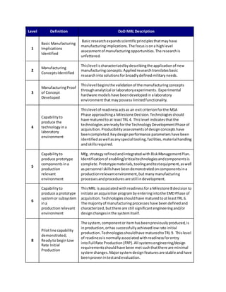
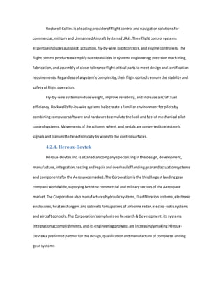
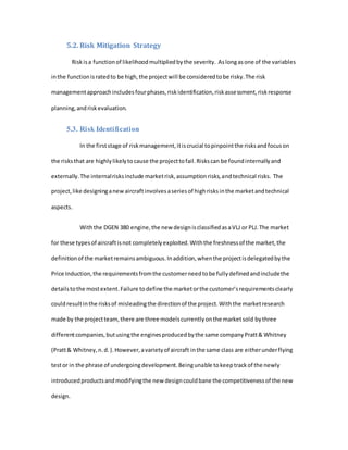
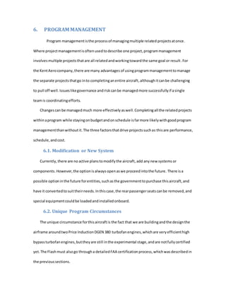
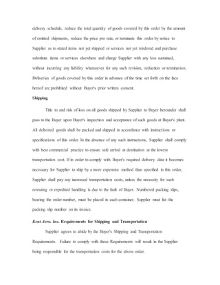
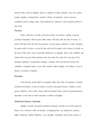
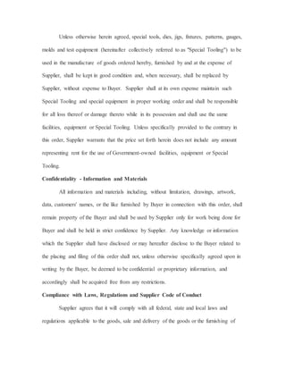
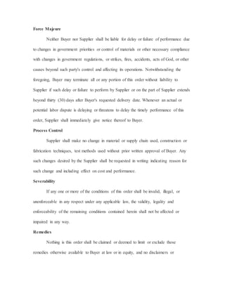
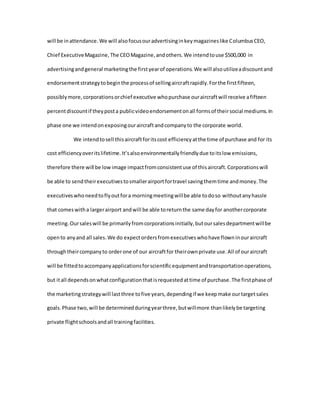
![𝑏 = √ 𝐴 ∗ 𝑆 --------------------------------------3.5.2-1
Sweep angle is another important parameter regarding wing design. Changing the
sweepangle hasmanyeffects on performance, such as stability due to shifting the MAC of the
wing, or helping to avoid the onset of shock waves. From historical statistics (Raymer, 2012), a
sweep angle of approximately 2.0 degrees would be sufficient for the given aircraft.
3.4.3 Fuselage Geometry
The layoutof a fuselage isgenerallydependentonthe TOGW and the functionof the
aircraft.The primaryfunctionof the designedaircraftistocarry passengers.Giventhe number
of passengersandcrews,the lengthanddiameterof the fuselage will eventuallybe determined.
However,since the proposedaircraftisalsodesignedtoundertake someothertasksmore than
carryingpassengers,otherconsiderationsshouldalsobe takenintoaccount.Fromthe historical
statistics,the followingequation(Eq.3.5.3-1) will be usedtodetermine the lengthof the
fuselage:
𝐿 𝑓𝑢𝑠𝑒𝑙𝑎𝑔𝑒 = 𝑎𝑊0
𝐶
---------------------------------------Eq.3.5.3-1
The TOGW has been determined. Based on the major assumptions made in section 3.4.5,
the length of the fuselage is calculated to be 25.87 [𝑓𝑡]. The maximum fuselage diameter is
determined by the ratio between fuselage length and maximum fuselage diameter, which is
referredasfinenessratio.Tominimize the drag produced by the fuselage, the fineness ratio is
around 3 (Raymer, 2012). As a result, the maximum diameter of the fuselage is set to be 8.62
[𝑓𝑡].](https://image.slidesharecdn.com/253118ae-a5c9-40ed-ac48-410ea800dbaa-160802003508/85/Final-Report-Aircraft-Design-18-320.jpg)
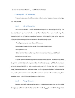
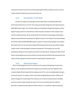
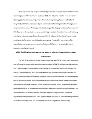
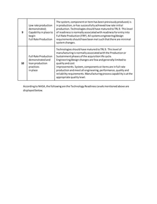
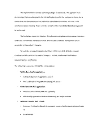
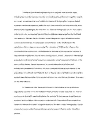
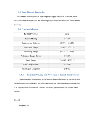
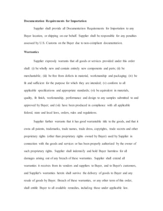
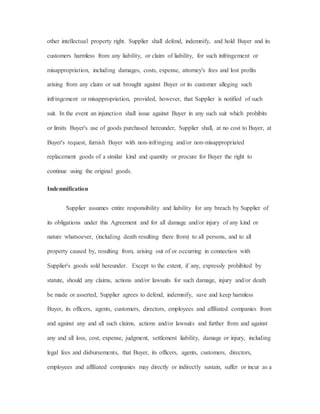
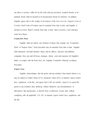
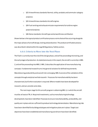
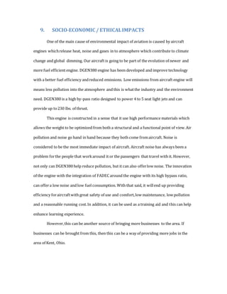
![The methodof calculatingthe parametersof tailsispertainingtothe definitionof tail
volume coefficient.The followingtwoequations,Eq.3.5.4-1and Eq. 3.5.4-2 define the horizontal
tail volume coefficientandthe vertical tail volumecoefficientrespectively:
𝑐 𝐻𝑇 =
𝐿 𝐻𝑇 𝑆 𝐻𝑇
𝐶 𝑊 𝑆 𝑊
----------------------------------Eq.3.5.4-1
𝑐 𝑉𝑇 =
𝐿 𝑉𝑇 𝑆 𝑉𝑇
𝑏 𝑊 𝑆 𝑊
-----------------------------------Eq.3.5.4-2
Withthe resultsof winggeometrycalculationsandassumptionsmade insection
3.4.5, the area of the horizontal tail is59.55 [𝑓𝑡2] and the area of the vertical tail is41.30 [𝑓𝑡2].
The methodto calculate the othertail parameters,suchasroot chord, tipchord,span, lengthof
the MAC, and locationof the AC isthe same as the methodusedforwinggeometrycalculation.
Those parameterswill be listedundersection3.11.3.
3.5. Thrust-to-Weight Ratio
The wingswere primarilydesignedtosupportstabile handlingandlongendurance applications.
The thrust to weightratioiscalculatedtobe 25 lb/ft².
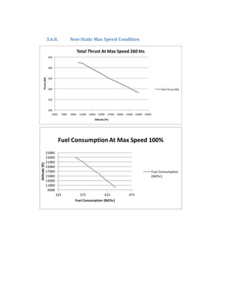
3.6. Introduction to Powerplant Data
Performance isone of the mostsoughtafterfactors whendevelopinganew aircraft.It does
not matterwhatkindof aircraft:helicopter,airplane,military,transport,orcargo.You will
alwaysrelyonthe performance of the aircraftto complete the taskat hand.The
mission/objective couldbe takingpassengersfromChicagotoNew York,or a Militaryjointstrike
fighterneedingtotake off froma carrier to dropa payloadovera conflictzone inanother
country.Each missionhasitsown setof establishedperformanceparametersthatthe aircraft
needstomeetinorderto successfullycompletethe objective.Wheninthe designphase,itis](https://image.slidesharecdn.com/253118ae-a5c9-40ed-ac48-410ea800dbaa-160802003508/85/Final-Report-Aircraft-Design-20-320.jpg)
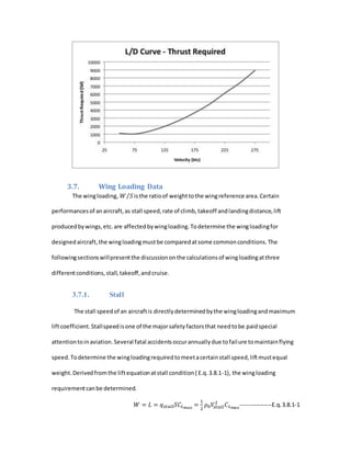
![The formulafor wingloadingrequirementforstall givesaresultof 44.79 [𝑙𝑏𝑓 𝑓𝑡2]⁄ . This
calculationisalsodone with 𝐶 𝐿 𝑚𝑎𝑥
of 1.55, a stall velocityof 155.83 fps,and air densityof
0.0024[𝑠𝑙𝑢𝑔 𝑓𝑡3]⁄ at sea level standard(SLS).
3.7.2. Takeoff
To determine the requiredwingloadingtomeetagiventakeoff distance requirement,
the followingexpression(E.q.3.8.2-1) isused.Inthiscalculation,the assumedtakeoff distance is
2,500 feet.The takeoff parameter(TOP) canbe foundfromfig5.4 inthe Raymertext,Aircraft
Design:A Conceptual Approach(Raymer,2012).
𝑊 𝑆⁄ = (𝑇𝑂𝑃)𝜎𝐶 𝐿 𝑇/𝑂
(𝑇 𝑊⁄ ) 𝑇/𝑂 --------------------E.q.3.8.2-1
The wingloadingrequirementfortakeoff comesouttobe 29.96[𝑙𝑏𝑓 𝑓𝑡2]⁄ . The calculated
𝐶 𝐿 𝑇/𝑂
is 1.281. Othervariablesusedinthe equationare the TOPwhichisassumedtobe 120,
densityratioof 1, and (𝑇 𝑊⁄ ) 𝑇/𝑂 of 0.1949.
3.7.3. Cruise
Determiningawingloadingforcruise is utmostimportant.The cruise conditionis
typicallythe mostdesignedaroundfactoronan aircraft. Choosingawingloadingfactorthat
directlysuitsthe cruise conditionforamaximumrange isproblematic.The wingloadingfactor
for a maximumrange ismuchhigherthan the wingloadingfactorrequiredforstall andother
characteristics.Itwouldbe unsafe toflywithsucha small wing,hence where understandingthe
importance of trade-offscomesintoplay.Tocalculate the wingloadingformaximumrange, the
followingequation(E.q.3.8.3-1) istobe used.
𝑊 𝑆⁄ = 𝑞 √ 𝜋𝐴𝑒𝐶 𝐷0
/3---------------------------E.q.3.8.3-1
The dynamicpressat the cruise conditionisdeterminebythe airdensityatcruise
altitude (FLl80) andthe cruise speed.Forjetaircraft, the Oswaldefficiency(e) andthe zero-lift](https://image.slidesharecdn.com/253118ae-a5c9-40ed-ac48-410ea800dbaa-160802003508/85/Final-Report-Aircraft-Design-37-320.jpg)
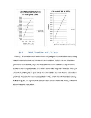
![drag coefficient(𝐶 𝐷0
) are statisticallyassumedtobe 0.8 and 0.015 respectively.Aftertakingall
the variantsintothe above formula,the wingloadingatthe cruise conditioniscalculatedtobe
27.39[𝑙𝑏𝑓 𝑓𝑡2]⁄ .
3.7.4. Discussionof the Wing Loading
To determine the endwingloadingrequirement,all differentflightoperationsmustbe
considered,suchasstall,landing,takeoff,andcruise.Topickthe exactwingloadingthatwill be
usedforthe design process,the lowestcalculatedfromall of the flightconditionsistobe used.
Afterthe comparingthe resultsof the above calculation,the requiredwingloadingis
27.39[𝑙𝑏𝑓 𝑓𝑡2]⁄ . Selectingthe lowestwingloadingimpliesthatthe aircrafthas enoughliftbeing
producedbythe wing,for the givenweight.
3.8. Sizing Results and Design Selection
3.8.1. Sizing Variability and Optimization
Varythe wingloadingbyplus/minus20% andthe aspectratioby plus/minus20% to
determine the optimumcombinationusingthe carpetplotmethodof Chap.19.
3.9. Sizes and Capacities
3.9.1. Fuselage
Fuselage Length:25.86 [𝑓𝑡]
Fuselage maximumdiameter:8.62[𝑓𝑡]
3.9.2. Wing
Wingspan:37.34 [𝑓𝑡] Root chord:7.66 [𝑓𝑡]
Surface area: 178.76 [𝑓𝑡2] Root chordthicknessratio:15%
Wettedarea:732.92 [𝑓𝑡2] Tip chord:1.91 [𝑓𝑡]
Taper ratio:0.25 Tip chordthicknessratio:12%](https://image.slidesharecdn.com/253118ae-a5c9-40ed-ac48-410ea800dbaa-160802003508/85/Final-Report-Aircraft-Design-38-320.jpg)
![LE Sweepangle:2[degree] MAC length:5.36 [𝑓𝑡]
Aspectratio:7.8 MAC location:7.47 [𝑓𝑡]
3.9.3. Tail
- Horizontal Tail
Root chord:5.41[𝑓𝑡] Aspectratio:5.2
Tip chord:1.35 [𝑓𝑡] Arm length:12.93 [𝑓𝑡]
Span:17.60 [𝑓𝑡] Taper Ratio:2.5
Area:59.55 [𝑓𝑡2]
- Vertical Tail
Root chord:8.39 [𝑓𝑡] Area:41.29 [𝑓𝑡2]
Tip chord:2.10 [𝑓𝑡] Aspectratio:1.5
Span:7.87 [𝑓𝑡] Arm length:12.93 [𝑓𝑡]
Taper ratio0.25
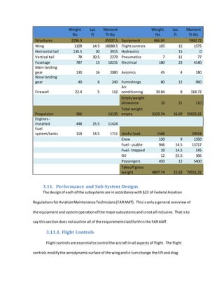
3.9.4. Landing Gear
The landinggearare designedtohave atotal addedheightof 16 inchesto the aircraft.
Witha tricycle type gearconfiguration,eachstrutwill have asingle Type III(low pressure)
wheel. More detail willbe giveninalaterdiscussion.
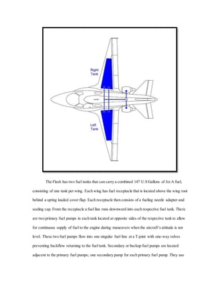
3.9.5. Fuel
The fuel systemiscapable of holding986 lbf of Jet-A fuel or147 gallons. More detail will
be givenina laterdiscussion.
3.9.6. Power Plant
The FlashfeaturestwoDGEN 380 enginesmountedaftof the wings. Each engine weighs
175 lbf andis 4 feet,5 inchesinlength. More detail will be giveninalaterdiscussion.](https://image.slidesharecdn.com/253118ae-a5c9-40ed-ac48-410ea800dbaa-160802003508/85/Final-Report-Aircraft-Design-39-320.jpg)
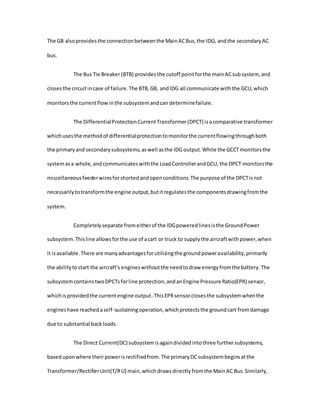


![REFERENCES
Abbott, I., Doenhoff, A., & Stivers, L. National Advisory Committee for Aeronautics,
(1945). Summary of airfoil data (Report NO.824)
MOOG, INC. (2013). Flight Control Actuation. 3
Nicholas, J., & Steyn, H. (2012). Project management for engineering, business and
technology (4th ed.). New York, NY: Routledge.
Raymer, D. (2012). Aircraft Design: A Conceptual Approach (5th ed.). Reston, VA: American
Institute of Aeronautics and Astronautics, Inc.
Remer, Dale. D. (1996). Aircraft Systems For Pilots. Englewood, Co: Jeppesen 3
Sanderson Training Products.
Sadraey, M. (2012). Aircraft Design: A Systems Engineering Approach. N.p.: Wiley Publications
Turbofan Engine: PW600. (n.d.). In Pratt & Whitney Canada. Retrieved March 29, 2015, from
http://www.pwc.ca/en/engines/
AcqNotes.(2015).ManufacturingReadinessLevel(MRL) - AcqNotes.Retrievedfrom
http://acqnotes.com/acqnote/careerfields/manufacturing-readiness-levelmanufact
Airbus. [Graph Image]. Retrieved from
http://www.airbus.com/uploads/pics/Material_andLogistics_intro_section__1_.png
Cornell University Law School. (n.d.). 48 CFR 7.105 - Contents of written acquisition plans. |
LII / Legal Information Institute. Retrieved April 14, 2015, from
https://www.law.cornell.edu/cfr/text/48/7.105
DoD ManufacturingReadinessReferencesandLinks.(n.d.).Retrievedfromhttp://www.dodmrl.com/
Garmin.(n.d.).AboutUs| Garmin | UnitedStates.Retrievedfromhttp://www.garmin.com/en-
US/company/about/](https://image.slidesharecdn.com/253118ae-a5c9-40ed-ac48-410ea800dbaa-160802003508/85/Final-Report-Aircraft-Design-121-320.jpg)
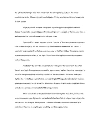
![Garmin.(n.d.).G1000 | Garmin. Retrievedfromhttps://buy.garmin.com/en-US/US/in-the-air/flight-
decks/g1000-/prod6420.html
Heroux-DevtekInc.(2010).Corporate Profile - Heroux-DevtekDesigner,DeveloperandManufacturerof
Aerospace &Industrial Products.Retrievedfrom
http://www.herouxdevtek.com/company/corporate-profile
Kollmorgen. (n.d.). Supplier Terms & Conditions | Kollmorgen. Retrieved from
http://www.kollmorgen.com/en-us/service-and-support/partners/supplier-terms-
conditions/
Majerowicz, W., & The Boeing Company. (2001, November). Schedule Analysis Techniques
[PDF]. Retrieved from http://www.evmlibrary.org/library/TP-
16%20Schedule%20Analysis%20Techniques,%20Majerowicz.pdf
National AeronauticsandSpace Administration.(2014,February3).TechnologyReadinessLevel|NASA.
Retrievedfromhttps://www.nasa.gov/content/technology-readiness-level/#.VTnRPSFViko
OR-AS. PM Knowledge Center. (n.d.). Schedule Risk Analysis: How to measure your baseline
schedule?s sensitivity? | PM Knowledge Center. Retrieved from
http://www.pmknowledgecenter.com/dynamic_scheduling/risk/schedule-risk-analysis-
how-measure-your-baseline-schedule%E2%80%99s-sensitivity
Pcubed. (2015). Definition: What is Program Management. Retrieved from
http://www.pcubed.com/services/glossary.program
Price Induction.(n.d.).AboutUs| Price Induction.Retrievedfromhttp://www.price-
induction.com/about-us/who-we-are/
Rockwell Collins.(2015).FlightControls.Retrievedfrom
https://www.rockwellcollins.com/Products_and_Systems/Controls.aspx](https://image.slidesharecdn.com/253118ae-a5c9-40ed-ac48-410ea800dbaa-160802003508/85/Final-Report-Aircraft-Design-122-320.jpg)