This document provides an overview of the flight deck and systems of the Airbus A330 aircraft. It includes descriptions of the flight deck layout, visibility from the flight deck, and control panels. The key aspects summarized are:
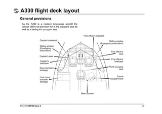
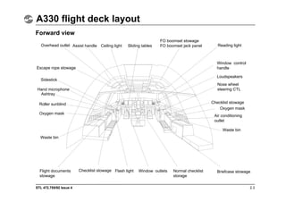
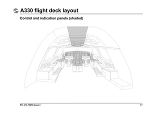
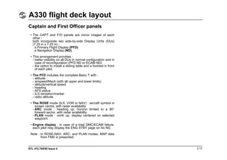
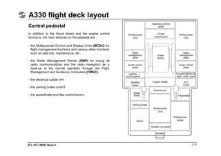
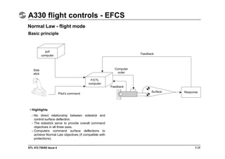
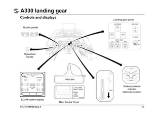
- The flight deck accommodates a crew of two with provisions for additional occupants. It features sidestick controllers, electronic displays, and ergonomically arranged control panels.
- The flight deck windows and layout provide excellent external visibility for pilots, meeting or exceeding industry standards.
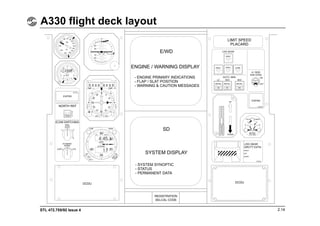
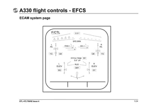
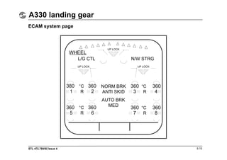
- Electronic displays and the Electronic Centralized Aircraft Monitor (ECAM) integrate aircraft systems information and monitoring on interchangeable and switchable display units.


![STL 472.755/92 Issue 4
A330 automatic flight system - guidance function
10.11
Vertical modes Common modes
• In CLB/DES modes vertical path is maintained as
defined by the FMGC, taking into account the flight plan
constraints inserted in the system at the clearance
altitude selected on the FCU.
• OP CLB (OP DES) mode allows the aircraft to climb or
descend uninterrupted toward FCU selected altitude,
maintaining a TARGET SPEED (managed or selected)
with a fixed given thrust. ALT constraints are ignored.
Altitude hold
• It is active if aircraft reaches FCU altitude, intermediate
flight plan altitude constraints when ALT pushbutton is
depressed on FCU or when V/S is set to zero.
V/S/FPA
• V/S/FPA is engaged by pulling on V/S/FPA selector.
V/S or FPA value can be selected before or after a pull
action.
Approach • ILS available
- GLIDE capture and track
- FLARE
- LAND
- ROLL OUT
• ILS not available, RNAV approach
selected on MCDU :
- LATERAL guidance on the F-PLN
- VERTICAL guidance and descent
allowed down to MDA.
Take-off • SRS
- with engines running V2 + 10 holding
- with one engine out VA (1) holding if VA>V2
V2 holding if VA<V2.
(1) VA = aircraft speed when the engine
failure occurs.
• RWY :
- Track hold or LOC centerline hold.
Go-around • SRS (as take-off).
• GA TRK hold.
Level changes [managed guidance (CLB, DES), selected
guidance (OP CLB OP DES)].](https://image.slidesharecdn.com/a330flightdeckandsystemsbriefingforpilots-230702040413-640dda7d/85/A330_Flight_Deck_and_Systems_Briefing_For_Pilots-pdf-131-320.jpg)


