Downloaded 267 times

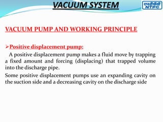
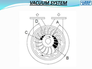
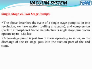
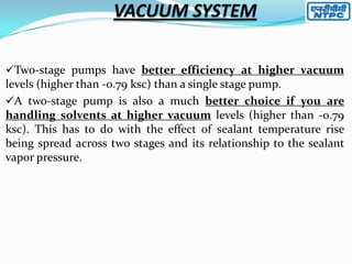
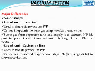
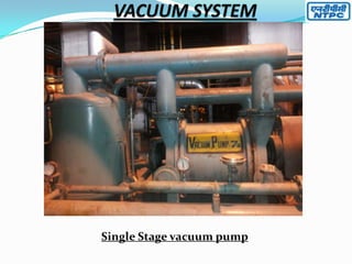
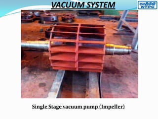
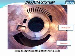
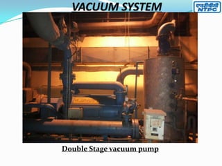
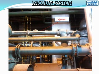
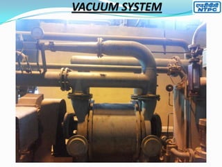
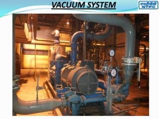

The document describes air evacuation systems used in industrial processes. It discusses the components and working principles of single-stage and two-stage liquid ring vacuum pumps. A single-stage pump uses suction and compression to pull a vacuum and return gas to atmospheric pressure in one revolution. Two-stage pumps are more efficient at higher vacuums and for handling solvents as they spread the temperature rise across two stages. The document also outlines common problems with liquid ring vacuum pumps like reduced capacity, noise, overheating and vibration and their potential causes.


