

Recommended
Recommended
More Related Content
What's hot
What's hot (20)
Viewers also liked
Viewers also liked (14)
Similar to 2. article azojete vol 11 13 23 ngala
Similar to 2. article azojete vol 11 13 23 ngala (20)
More from Oyeniyi Samuel
More from Oyeniyi Samuel (20)
Recently uploaded
Recently uploaded (20)
2. article azojete vol 11 13 23 ngala
- 1. Arid Zone Journal of Engineering, Technology and Environment. August, 2015; Vol. 11: 13-23 Copyright© Faculty of Engineering, University of Maiduguri, Nigeria. Print ISSN: 1596-2490, Electronic ISSN: 2545-5818 www.azojete.com.ng A CFD ANALYSIS OF A MICRO HORIZONTAL AXIS WIND TURBINE BLADE AERODYNAMICS Ngala, G.M1* ., Shuwa, M2 ., Oumarou, M.B1 ., and Muhammad, A.B1 . (1 Department of Mechanical Engineering University of Maiduguri, Maiduguri, Nigeria. 2 Center for Entrepreneurial and Enterprise Development University of Maiduguri, Maiduguri, Nigeria.) *Corresponding authors e-mail: garba.ngala68@gmail.com Abstract This study investigates the performance of a micro Horizontal Axis Wind Turbine (HAWT) blade using Computational Fluid Dynamics (CFD). The 1.5 m long micro HAWT blade was designed using the Blade Element Momentum Theory (BEM). Parameters such as the chord length lift force, drag force, tip speed ratio, solidity, coefficient of performance, angle of attack, wind relative angle, Reynolds number, efficiency, axial and induction factors were determined. Based on the design parameters the micro blade was created, meshed and boundary conditions identified in a 2D pre-processor Gambit interface. The meshed blade was exported to Fluent where it was processed and analyzed based on the identified boundary condition. The blade was simulated based on Maiduguri environment which has a recorded average wind speed of 3.89 m/s and the result showed that the maximum extractable power was 142.66 watts at a wind relative velocity of 4.8m/s when the blade was at 8o angle of attack and 3 x 10⁶ Reynolds Number. Measured power increased consistently with increased in wind speed, and with a turbine efficiency of 28% the blade satisfied the Newton’s third law and the Bernoulli’s effect. The profile had the ability to perform and serve as a means of extracting and generating energy from wind, which is a renewable, clean and locally available source of energy in Maiduguri and its environs. The use of this energy source will reduce the large dependence on non-renewable, expensive and environmentally unfriendly means of energy generation. Further studies could be carried experimentally to verify the simulation results. Keywords: Computerized Fluid Dynamics, wind turbine, aerodynamics Nomenclature P - The Extractable Power from the wind A - Swept Area of the Rotor ρ - Air Density v - Wind Relative Velocity d - Rotor Diameter r - Rotor Radius C - Chord Length ω - Angular Velocity of the Rotor θ - Angle of Attack ϕ - Wind Relative Angle η - Efficiency of the Blade on the Wind Turbine L - Blade Span ṙ - Radial Length of the Blade Element dṙ - Increase in Blade Span Length
- 2. Ngala et al.: A CFD Analysis of a Micro Horizontal Axis Wind Turbine Blade Aerodynamics. AZOJETE, 11: 13-23 14 T - Rotor Torque σ - Solidity λr - Tip Speed Ratio Cp - The Power Coefficient CL - Coefficient of Lift CD - Coefficient of Drag FL - Lift Force FD - Drag Force ɑ - Axial Induction Factor a׳ - Radial Induction Factor Re - Reynolds Number F - Resultant Force B - Number of Blades PT - Power Developed by the Turbine N - Speed of the Rotor T - Temperature 1. Introduction The wind is a free-flowing fluid stream as a result temperature difference cause by solar radiation on the earth surface. The free-flowing stream possesses a kinetic energy which can be extracted and converted to other useful means especially to electricity through the use of a wind turbine (Patil, 2009). The energy extraction device (wind turbine) is submersed into this stream and can convert a certain amount from the total available energy in the fluid stream into mechanical then to electrical energy. There are two types of wind turbines, horizontal and vertical axis wind turbines. Horizontal Axis Wind Turbines (HAWT) have the axis of rotation of their blades horizontal to the ground and almost parallel to the wind stream, while the Vertical Axis Wind Turbines (VAWT) have the axis of rotation and blades vertically oriented (Ngo and Natiwitz, 2010). Most of the wind turbines fall under the category the Horizontal Axis Wind Turbines because they have some distinct advantages such as low cut-in wind speed and easy furling. In general, they show relatively high power coefficient (Rajakumar and Raviandran, 2010). A Horizontal Axis Wind Turbine consists of four main parts, namely the rotor, generator, gearbox and the control system. The rotor consists of the blade, the hub and the shaft, the blade is key element of wind turbines which converts the kinetic energy of the wind to mechanical and then to electrical energy. In order to extract the maximum kinetic energy from the wind the blade airfoil (geometry) should be effectively designed. An airfoil means a two dimensional cross- section shape of a blade whose purpose is to either generate lift or minimize drag when exposed to a moving fluid (Chandrala, 2012). This study is aimed at investigating the aerodynamic behavior of the blade according to designed parameters, which include the rated wind speed, rotor diameter, design tip speed ratio and design angle of attack.
- 3. Arid Zone Journal of Engineering, Technology and Environment. August, 2015; Vol. 11: 13-23 15 Aerodynamic optimization of the rotor blades is associated with optimization of the chord, twist distribution and choice of airfoil shape. There are a vast number of multi-dimensional optimization methods available for blade design, and some of these are available as computational fluid dynamic functions. Aerodynamic performance of wind turbine blades is analyzed using Computational Fluid Dynamics (CFD), which is one of the branches of Fluid Mechanics that uses numerical methods and algorithms to analyse and solve problems of fluid flows (Bai et al., 2013). Meanwhile, blade element momentum (BEM) method can be used for the blade structure analysis. The blade element momentum (BEM) method consists of dividing the flow into annular control volumes and applying momentum balance and energy conservation in each control volume. The annuli are bounded by stream surfaces that enclose the rotor and extend from far upstream to far downstream. This is used to obtain the distribution of the angle of relative wind which consists of pitch angle, twist angle and angle of attack on the blade sections (airfoil) and as well the forces acting on the airfoil section such as the thrust and the torque. Both are generated by lift and drag forces, with the lift and drag being functions of the angle of attack and the Reynolds number (Petal and Damania, 2013). To carry out a CFD analysis the designed blade geometry is created in a Gambit interface. Gambit is the pre-processor of ANSYS-Fluent, a computational fluid dynamics software that does 2-D and 3-D modeling of the mechanical component to be simulated, while on the other hand Fluent is also computational fluid dynamic software that is used in engineering design by applying fundamentals laws of mechanics of fluid and the conservation of mass, momentum and energy equation to analyze and solve an engineering problem without the need of a prototyping (Farooq and Harmain, 2013). The equations normally generated form a set of couple and nonlinear partial differential equations. Solving such equations analytically is usually difficult or even not possible for most engineering problems, thus the need for CFD application (Petal and Damania, 2013). First task in CFD analysis is preparation of geometry. Here, the type of airfoil to be used is calculated or decided. This is followed by the establishment of the airfoil co-ordinate for drawing the airfoil shape using Gambit. Then meshing is carried out, and with the boundary condition specified, it is exported to Fluent for iteration, analysis and observations. 2. Methodology The methodology adopted for this study involved the following: 1. A horizontal axis wind turbine blade was designed using Blade Element Momentum (BEM) Theory. Blade element theory assumes that blades can be divided into multiple elements, which can act independently as two-dimensional airfoils. The forces and moments can be calculated separately then summed to obtain the overall blade forces and moments. Blade parameters which include chord length (C), rotor diameter (D), blade radial length , blade relative angle blade span (L), angle of attack (θ), tip speed ratio ( , solidity ( lift force (FL), drag
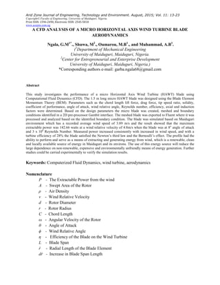
- 4. Ngala et al.: A CFD Analysis of a Micro Horizontal Axis Wind Turbine Blade Aerodynamics. AZOJETE, 11: 13-23 16 force (FD), the power coefficient (CP), turbine blade efficiency ( axial (a) and radial ( ) induction factors are as shown in Figure 1 below. These were calculated using equations 1 - 15 Figure 1: Blade aerodynamic parameters The chord length (C) is the length from the leading edge to the trailing edge of a blade cross section that is parallel to the vertical axis of symmetry (Chandrala, et al., 2012) and is given by Equation 1 and the wind relative angle ( is given by Equation 2. (1) (2) The tip speed ratio ( is the ratio of the blade tip speed over wind speed. It is a significant parameter for wind turbine design (Han, 2011) and its definition is shown in Equation 3 below. The blade (3) The angle of attack ( is the angle between the incoming flow stream and the chord line of the airfoil. At low angles of attack, the dimensionless lift coefficient increases linearly with angle of attack and drag is reasonably small. Flow is attached to the airfoil throughout this regime. At an angle of attack of roughly 100o , the flow on the upper surface of the airfoil begins to separate and a condition known as stall begins to develop. The dimensionless lift coefficient peaks and the dimensionless drag coefficient increases as stall increases (Ajao and Adegan, 2009). The angle of attack is given by Equation 4.
- 5. Arid Zone Journal of Engineering, Technology and Environment. August, 2015; Vol. 11: 13-23 17 (4) Solidity ratio ( is the ratio of the area occupied by the blade to the available free space and is given by Equation 5. (5) The lift force (FL) given by Equation 6 is the force acting on the blade perpendicular to the undisturbed wind flow and the drag force (FD) given by Equation 7 is the force acting on the blade in the direction of the undisturbed wind flow(Kevadiya and Vaidya, 2013). (6) (7) The axial induction factor (a) and radial induction factor ( ) are given by equation (8) and equation (9) respectively (Kale and Varma, 2014). (8) (9) The power coefficient is a measure of the mechanical power delivered by the rotor to the turbine’s low-speed shaft. It is defined as the ratio of the mechanical power to the power available in the wind (Ajao and Adegan, 2009) and is given by Equation 10. (10) The efficiency of a wind turbine is defined as the ratio between power coefficient Cp and the Betz limit, Betz = 16/27 ≈ 0.593. This value was deduced by Albert Betz who was a German physicist in 1919, and who noted that 0.593 is the maximum power efficiency of a wind turbine which converts the kinetic energy of the wind to mechanical energy of the blade. Therefore the efficiency of the blade on the wind turbine is given by equation (11) below (Han, 2011, Naveed et al., 2011).
- 6. Ngala et al.: A CFD Analysis of a Micro Horizontal Axis Wind Turbine Blade Aerodynamics. AZOJETE, 11: 13-23 18 (11) 2. A Computational Fluid Dynamic (CFD) analysis using Fluent and Gambit of the designed blade was carried out to investigate the viability of the blade. A 2D geometry of the designed blade was created within a computational domain in Gambit interface. The domain was meshed and boundaries selected with Farfield 1 (JKL) as velocity inlet, Farfield 2 (MON) as pressure outflow and upper (LN) and lower (JM) surfaces of the domain as symmetry walls while the blade was considered as a wall within the computational domain as shown in Figure 2 below. Figure 2: The computational domain The mesh was exported to Fluent 6.2, where the applied fundamental laws of mechanics of fluid and equations of conservation of mass and momentum were analyzed and solved based on the CFD Navier-Stokes system of equations (Continuity Equation, Momentum Equation and Energy Equation) shown: Continuity Equation (12) Momentum Equation (13) (14) Energy Equation (15)
- 7. Arid Zone Journal of Engineering, Technology and Environment. August, 2015; Vol. 11: 13-23 19 3. Results and Discussion The simulation was carried out based on environmental parameters of Maiduguri, Borno State Northeastern Nigeria. The flow over the airfoil was analyzed when the continuum used was air with the properties shown in Table 1 under the following operating conditions: i. Atmospheric Pressure 101325 Pascal ii. Atmospheric Temperature 308 K Figure 3: The structured grid Table 1: Properties of the continuum used The Model was analysed for Invicid, and Spalart-Allmaras viscous models under the Boundary Condition and Discretization Scheme indicated in Tables 2 and 3 .
- 8. Ngala et al.: A CFD Analysis of a Micro Horizontal Axis Wind Turbine Blade Aerodynamics. AZOJETE, 11: 13-23 20 Table 2: Boundary conditions Table 3: Discretization scheme From the condition in Tables 1, 2 and 3 above and on the basis of the airfoil at 8o angle of attack the simulation result revealed the contours of velocity and pressure distribution of an Invicid, and Spalart-Allmaras viscous models as shown in Figures 4-6. Figure 4: Velocity and pressure distribution under an Invicid model
- 9. Arid Zone Journal of Engineering, Technology and Environment. August, 2015; Vol. 11: 13-23 21 Figure 5: Velocity and pressure distribution under model Figure 6: Velocity and pressure distribution under Spalart-Allmaras model Figures 4, 5 and 6 show the pressure distribution on the airfoil surface. One side of the airfoil experiences higher pressure than the other resulting in a higher lift than drag. Also in the three results, the head of the airfoil is exposed to low pressure and high velocity zone thus allowing the
- 10. Ngala et al.: A CFD Analysis of a Micro Horizontal Axis Wind Turbine Blade Aerodynamics. AZOJETE, 11: 13-23 22 higher air velocity to drive the blade. The airfoil tail does not experience any resistive air pressure. The work performed by this part of the airfoil is significantly less. This result satisfies the Bernoulli Effect and Newton’s Third Law. The airfoil was in conformity with NACA airfoil 4419 which as well has suitable lift to drag coefficient. However, based on the velocity distribution of the results, the airfoil power extracting ability is shown in Figure 7. Figure 7: The extractable power from the wind curve 4. Conclusion Turbine blade profile has been designed and the airfoil (blade geometry) created in 2D Gambit interface. Meshed boundaries were selected and simulated using the Computational Fluid Dynamic (CFD) code FLUENT 6.3. The design criteria were experimentally verified by testing the physically developed blade and the result compared with the iteratively simulated CFD model. At a wind speed of 4.8 m/s the simulation results shows a power output of 142.66 watts which will be generated at 8o angle of attack. Clear correlation was been found between the experimental and the simulation results. At a wind speed of 4.8 m/s the simulation result shows a power output of 142.66 watts while in the experimentation the power output was 140.85 watts. Therefore the developed HAWT blade profile has shown the ability to perform, thus the airfoil will really be a means of extracting and generating energy from wind, a renewable, clean and locally available source of energy in Maiduguri and environs. References Ajao, KR. and Adegun, IK. 2009. Development and power performance test of a small three- bladed horizontal-axis wind turbine. Journal of American Science, 5: 71-78.
- 11. Arid Zone Journal of Engineering, Technology and Environment. August, 2015; Vol. 11: 13-23 23 Bai, C., Hsiao, F., Li, M., Huang, G. and Chen, Y. 2013. Design of 10 kW Horizontal Axis Wind Turbine (HAWT) Blade and Aerodynamics Investigation Using Numerical Simulation, Elselvier Publishers Ltd. UK. Chandrala, M., Choubeg, A. and Gupta, B. 2012. Aerodynamic analysis of Horizontal Axis Wind Turbine blade, International Journal of Engineering Research and Applications, 2(6): 1244-1248. Farooq, A. and Harmain, G. 2013. Blade design and performance analysis of wind turbine. International Journal of Chemical Technology Research, 5 (2): 34-40. Han, C. (2011). Aerodynamics Analysis of Small Horizontal Axis Wind Turbine Blades by Using 2D and 3D CFD Modeling. Unpublished M. Eng. Thesis submitted to the University of the Central Lancashire, UK. Hau, E. (2006). Wind Turbines, 2nd Edition, Springer Ltd. UK. Kale, S. and Varma, R. (2014). Aerodynamic design of a Horizontal Axis Micro Wind Turbine Blade using NACA 4412 profile. International Journal of Renewable Energy Research, 4(1): 69- 73. Kevadiya, M, and Vaidya, H. 2013. 2D Analysis of NACA 4412 Airfoil, International Journal of Innovative Research in Science, Engineering and Technology, 2(5): 1686-1691. Naveed, D, Haris, H, Hammad, R. and SajidRaza, C. 2011. A Detail Aerodynamic Design and Analysis of a 2D Vertical Axis Wind Turbine using sliding mesh in CFD Publication of National Engineering and Scientific Commission, Pakistan. Patil, H. 2009. Experimental Work on Horizontal axis PCV Turbine Blade of Power Wind Mill, International Journal of Mechanical Engineering, 2(2): 75-85. Petal, H. and Daminia, S. 2013. Performance Prediction of Horizontal Axis Wind Turbine Blade, International Journal of Innovative Research in Science, Engineering and Technology, 2(5): 1401-1406. Rajakumar, S. and Ravindran, D. 2010. Computational Fluid Dynamics of Wind Turbine Blade At Various Angles Of Attack and Low Reynolds Number, International Journal of Engineering Science and Technology, 2(11): 1243-1248.