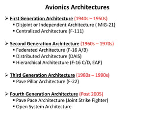
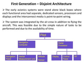
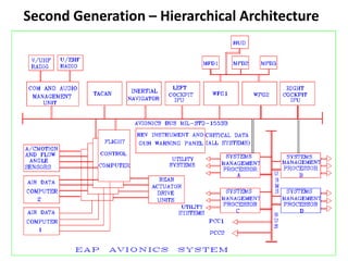
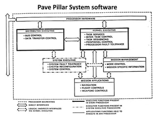
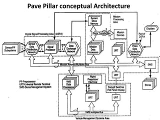
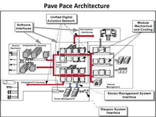
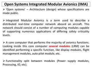
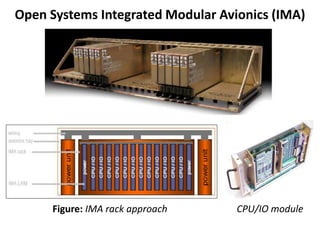
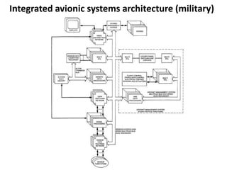
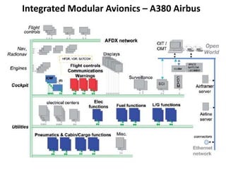
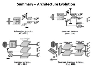
2. Avionics System Architecture
What is an architecture? – “The structure of components, their
relationships, and the principles and guidelines governing their
design and evolution over time”
Establishing the basic architecture is the first and the most
fundamental challenge faced by the designer.
The architecture must conform to the overall aircraft mission and
design while ensuring that the avionics system meets its performance
requirements.
These architectures rely on the data buses for intra and
intersystem communications.
4. First Generation – Disjoint Architecture
The early avionics systems were stand alone black boxes where
each functional area had separate, dedicated sensors, processors and
displays and the interconnect media is point-to-point wiring.
The system was integrated by the air-crew in addition to flying the
aircraft. This was feasible due to the simple nature of tasks to be
performed and due to the availability of time.
5. First Generation – Centralized Architecture
As the digital technology evolve, a central computer was added to
integrate the information from the sensors and subsystems.
The central computing complex is connected to other subsystems
and sensors through analog, digital, synchro and other interfaces.
Signal conditioning and computation take place in one or more
computers in a Line Replaceable Unit (LRU) located in an avionics
bay, with signals transmitted over one way data bus.
Data are transmitted from the systems to the central computer
and the data conversion takes place at the central computer.
Commonly found in rockets, missiles and satellites.
7. First Generation – Centralized Architecture
Advantages
Simple Design.
Software can be written easily.
Computers are located in readily accessible avionics bay.
Disadvantages
Requirement of long data buses.
Software changes somewhat difficult.
Increased vulnerability to damage.
Different conversion techniques needed at Central Computer.
8. Second Generation – Federated Architecture
Each system acts independently but united (Loosely Coupled).
Data conversion occurs at the system level and the data are send
as digital form – called Digital Avionics Information Systems (DAIS).
Several standard data processors are often used to perform a
variety of Low-Bandwidth functions such as navigation, weapon
delivery, stores management and flight control .
Systems are connected in a Time Division Multiplexing (TDM)
Highway.
Resource sharing occurs at the last link in the information chain –
via controls and displays.
9. Second Generation – Federated Architecture
Advantages
Contrast to analog avionics – digital processing provide precise
solutions over long range of flight, weapon and sensor
conditions.
Sharing of Resources.
Use of TDM saves hundreds of pounds of wiring.
Standardization of protocol makes the interchangeability of
equipments easier.
Allows Independent system design and optimization of major
systems.
Changes in system software and hardware are easy to make.
Fault containment – Failure is not propagated.
Disadvantages
Wasteful of resources.
11. Second Generation – Distributed Architecture
It has multiple processors throughout the aircraft that are
designed for computing takes on a real-time basis as a function of
mission phase and/or system status.
Processing is performed in the sensors and actuators.
Advantages
Fewer, Shorter buses.
Faster program execution.
Disadvantages
Potentially greater diversity in processor types which aggravates
software generation and validation.
12. Second Generation – Hierarchical Architecture
This architecture is derived from the federated architecture.
It is based on the Tree topology.
Most of the military avionics flying today based on Hierarchical
architecture.
Advantages
Critical functions are placed in a separate bus and Non-Critical
functions are placed in another bus.
Failure in non-critical parts of networks do not generate
hazards to the critical parts of network.
The communication between the subsystems of a particular
group are confined to their particular group.
The overload of data in the main bus is reduced.
14. Third Generation – Pave Pillar Architecture
Pave Pillar is a generic, conceptual architecture developed by the
USAF specifically targeted for advanced tactical fighters.
In general for all military aircraft applications, either air-to-air and
air-to-ground missions.
The Pave Pillar core avionics consists of the following functional
areas:
• Digital Signal Processing.
• Mission Processing.
• Vehicle Management Processing.
• Avionics Systems Control.
15. Third Generation – Pave Pillar Architecture
The Mission Processing Area – mission and system management
such as fire control, target acquisition, navigation management,
defense management, stores management, and crew station
management.
The mission processing area collects the health and status of all
avionics components.
The Vehicle Management Systems area provides the resources to
support the fundamental flight and airframe related control
functions: Flight Control, Inlet Control, Propulsion Control, Vector
Thrust Control, Air Data Measurement, Aircraft Inertial
Measurement, Electrical Power Control, Utility systems (Fuel
Measurement and Transfer, Crew escape system, Hydraulic System,
Landing Gear etc).
16. Third Generation – Pave Pillar Architecture
Avionics Systems Control is of all of the software in the system.
The avionics systems control functions of the operating system
shall be partitioned into three elements:
1) The system executive which will provide the monitoring of
system state and the reconfiguration based upon mission
requirements and detected system failures;
2) the distributed executive which will provide for decentralized
system control in each processor;
3) the kernel executive which will provide those operating system
functions which are common to all processors.
20. Open Systems Integrated Modular Avionics (IMA)
‘Open systems’ – Architecture (design) whose specifications are
made public.
Integrated Modular Avionics is a term used to describe a
distributed real-time computer network aboard an aircraft. This
network should consist of a number of computing modules capable
of supporting numerous applications of differing safety criticality
levels.
A core computer that performs the majority of avionics functions.
Looking inside this core computer several modules (LRM) can be
identified performing a specific function, like display modules, flight
management modules, auto pilot module, etc.
Functionality split between modules (Power supply modules,
Processing, IO, etc).
22. Integrated Modular Avionics – Features
Layered architecture using standard programming interface layers
to hide hardware and applications from one another.
Reconfiguration of applications on the modules. This can be static
reconfiguration (whilst the aircraft is not in use) or dynamic
reconfiguration (in flight).
Protection mechanisms to allow resources like memory to be
shared by multiple criticality level applications, and to allow
applications to be inserted/altered without impact on the rest of the
system. This is called partitioning.
Code re-use and portability.
An operating system to manage the applications.
Physical integration of networks, modules and IO devices.
23. Integrated Modular Avionics – Features
The software concept is also modular, comprising a number of
application programs running under the control of an executive
operating system.
A ‘Three layer stack’ modular software concept