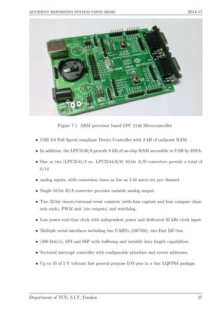
Downloaded 10 times


![Bibliography
[1] ADXL 335 - http://www.elechouse.com
[2] ARM-LPC2148 - http://www.nxp.com
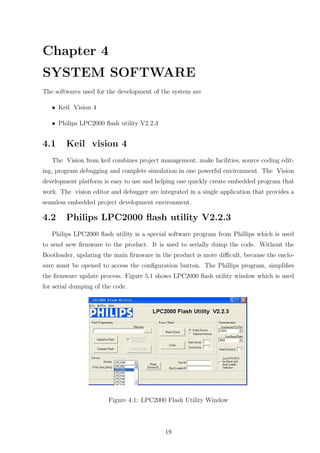
[3] GPS - http://www.ublox.com
[4] GSM - https://www.youtube.com/watch?v=wI-pQyG13ZM
24](https://image.slidesharecdn.com/accidentreortingsystemusingmems-150918203512-lva1-app6891/85/Accident-reporting-system-using-mems-28-320.jpg)

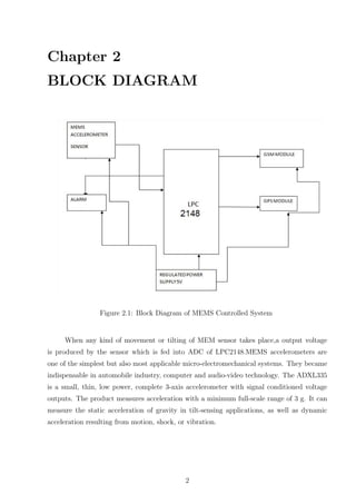
This document describes a MEMS-controlled accident reporting system that uses an accelerometer and GPS to detect vehicle accidents. When an accident occurs, the accelerometer detects vibrations and sends a signal to an ARM controller. The microcontroller then enables an airbag and sends a message with the accident location from the GPS to emergency contacts via GSM. The system aims to reduce response times and save lives by quickly notifying emergency services and relatives of accidents.


![Smart accident detector and intimator [autosaved]](https://cdn.slidesharecdn.com/ss_thumbnails/smartaccidentdetectorandintimatorautosaved-180331150920-thumbnail.jpg?width=640&height=640&fit=bounds)


