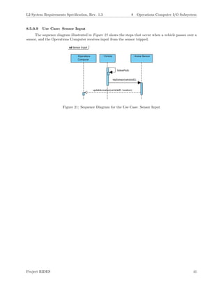
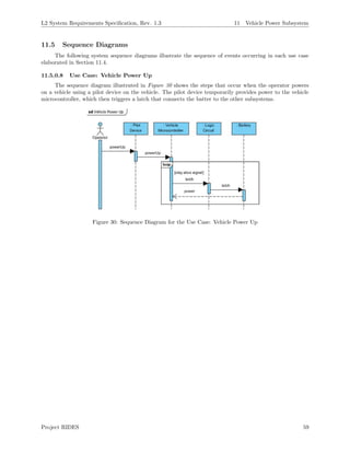
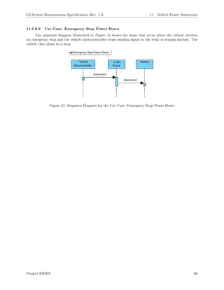
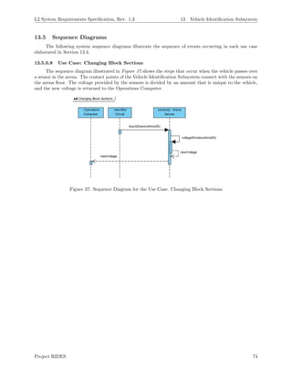
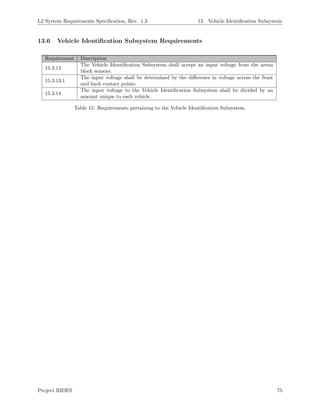
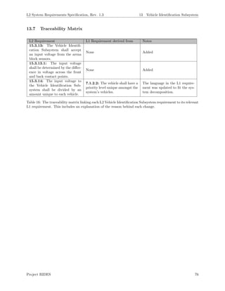
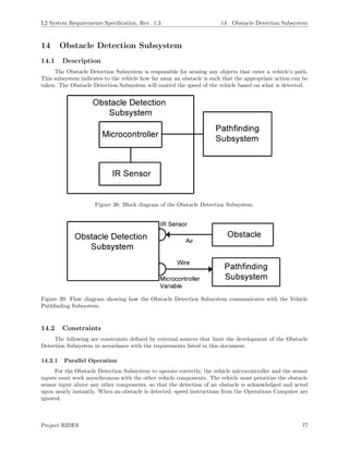
This document summarizes the system requirements for Project RIDES, which is being developed by Team Omni at Embry-Riddle Aeronautical University. It details the revision history of the document, provides an overview of the key subsystems and their requirements, and describes use cases and sequence diagrams for core functions like starting a ride, stopping a ride, and updating vehicle locations. The document is intended to specify the intellectual property and technical requirements for the autonomous vehicle project.
![L2 System Requirements Specification, Rev. 1.3 2 Stakeholders
2 Stakeholders
The following are the individuals and groups that are involved in or have an interest in the development
and completion of Project RIDES.
2.1 Team Omni
Team Omni will be involved in every aspect of the project s development. As the developers of Project
RIDES, the team shall be graded based on the rigor and difficulty of the project as well as its progress
over the year and ultimately, the project s completion. The team will apply knowledge of course content
gained throughout their academic careers attending Embry-Riddle Aeronautical University (ERAU). The
team members will be funding the project and are thus interested in completing it on time and under budget.
2.2 Dr. Garfield
As the project s customer and technical advisor, Dr. Garfield is interested in the completion of Project
RIDES. He will be consulted on a weekly basis and will influence all major design decisions.
2.3 Dr. Barott, Dr. Seker, and Richard Tubbesing
As the overseers of the capstone program, Dr. Barott, Dr. Seker, and Richard Tubbesing shall be
following the team s progress and providing guidance throughout the academic year. They will grade the
team based on their demonstration of the course requirements outlined in the course syllabus [1]. They will
continue to help the team define the scope of the project and will oversee the development process.
2.4 ERAU
ERAU administrators have an interest in student projects because their level of success reflects on
the institution. To ensure the safety of everyone on campus, ERAU requires that project s adhere to the
standards defined in the 2014-2015 Student Handbook [2]. The Student Handbook states that disciplinary
action will ensue when damage is done to public or private property [2:54]. Disciplinary action will also be
given if Team Omni is found in possession of items considered dangerous, including incendiary devices and
tools such as chain saws [2:53].
Project RIDES 7](https://image.slidesharecdn.com/65f3553e-d02d-46f7-98d6-0501a7f9d159-160107005120/85/Team-Omni-L2-Requirements-Revised-8-320.jpg)
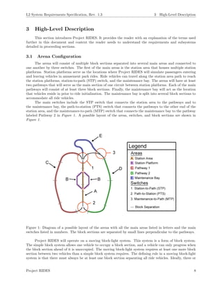
![L2 System Requirements Specification, Rev. 1.3 3 High-Level Description
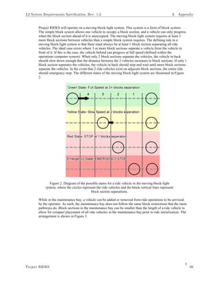
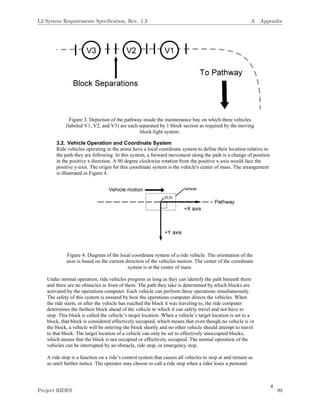
though no vehicle currently occupies the block section, a vehicle will be entering the block section shortly
and no other vehicle should attempt to travel to that block section. The target location of a vehicle can
only be set to effectively unoccupied block sections, meaning that the block section is not occupied and not
effectively occupied. The normal operation of the vehicles can be interrupted by an obstacle, a ride stop, or
an emergency stop.
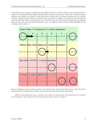
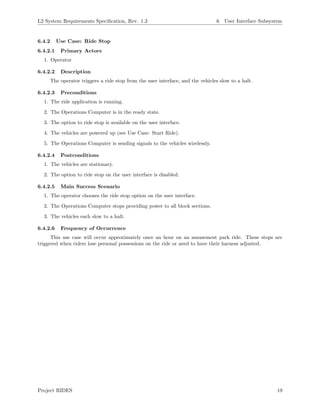
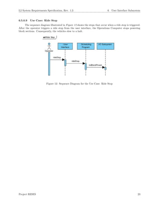
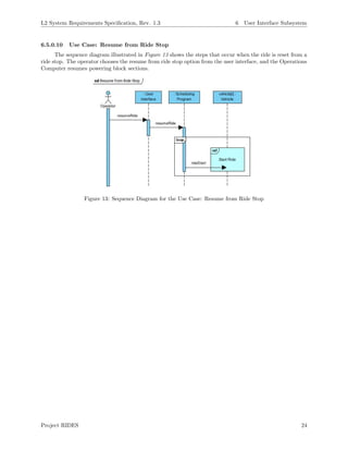
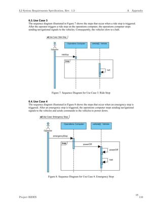
A ride stop is a function of a ride s control system that causes all vehicles to stop and remain stopped
until further notice. In amusement parks, an operator may choose to call a ride stop when a rider loses a
personal possession on the ride or needs to have their harness adjusted. The operator can choose to resume
the ride after triggering a ride stop, and the ride will proceed as normal.
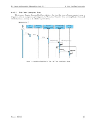
Emergency stops are used to stop the ride in such a manner that the ride will only operate again with
direct intervention from an operator. Typically, this must be reset by power cycling the ride [3]. In an
amusement park, an operator can choose to call an emergency stop if a danger is present to the riders or
one of the vehicles is not operating. The Operations Computer can also call an emergency stop if it detects
one of these events occurring.
Project RIDES 11](https://image.slidesharecdn.com/65f3553e-d02d-46f7-98d6-0501a7f9d159-160107005120/85/Team-Omni-L2-Requirements-Revised-12-320.jpg)
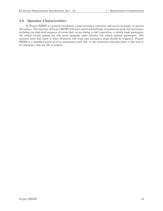
![L2 System Requirements Specification, Rev. 1.3 4 Requirements Considerations
4 Requirements Considerations
This section discusses the high-level assumptions made during the requirements process of Project
RIDES, the criterion that must be met before development, and what constraints are placed on development.
4.1 Project Constraints
The following are constraints defined by external sources that limit the development of Project RIDES
in accordance with the requirements enumerated further into this document.
4.1.1 Regulation Constraints
Project RIDES is envisioned to be a scale mock-up of an amusement park ride that would be used
for the enjoyment of passengers. Therefore, Project RIDES will be developed with consideration towards
the design standards for amusement park rides defined in ASTM F2291-14 that are unrelated to passengers
physically occupying the ride vehicles [4]. The regulations involving passenger safety are disregarded because
implementing features to meet them are impossible with the limited budget. The budget constrains the size
of the vehicles to be constructed. Regulations defined in ASTM F2291-14 specify minimum weight support
and require that ride vehicles are equipped with harnesses for the passengers. The small vehicle size prevents
Project RIDES from adhering to these regulations. The regulation will be met that specifies a minimum
separation between two vehicles in terms of the size of each vehicle. This specification applies during ride
operation but not for vehicles located in the maintenance bay.
4.1.2 Parallel Operation
The operation of Project RIDES is dependent on the ride vehicles operating in parallel with the
Operations Computer. After issuing instructions to the ride vehicles, the Operations Computer should
continue to instruct and monitor each vehicle.
4.1.3 Budget
Project RIDES is funded entirely by the student development team. The financial resources available
to the team are limited to approximately $1000. This constraint limits the development of Project RIDES
to a small number of vehicles unrepresentative of full-scale amusement park rides and limits the accuracy
with which the Operations Computer tracks the vehicles across block sections.
4.1.4 Schedule
Project RIDES must be completed by mid-May of 2015 for the sake of the grades of all Team Omni
members. The development of Project RIDES began in late August of 2014, so a total of 9 months were avail-
able for development. The scope of the project was made small enough that the goal of project completion
remains ambitious but attainable.
4.2 Assumptions and Dependencies
The following are assumptions made during the requirements extraction process of Project RIDES and
the project s dependencies.
4.2.1 Operation within the US
This project will take note of current standards for design of amusement park attractions by taking
note of attempting to adhere to standards as created by ASTM Committee F24 (Committee for Amusement
Rides and Devices). Specifically we will be designing our systems to take not of ASTM standard 2291
(Standard Practice for Design of Amusement Rides and Devices). It will also adhere to standards that are
present on US based rides based on operations of US theme parks, hence Project RIDES will have a US
focus operations wise.
Project RIDES 12](https://image.slidesharecdn.com/65f3553e-d02d-46f7-98d6-0501a7f9d159-160107005120/85/Team-Omni-L2-Requirements-Revised-13-320.jpg)
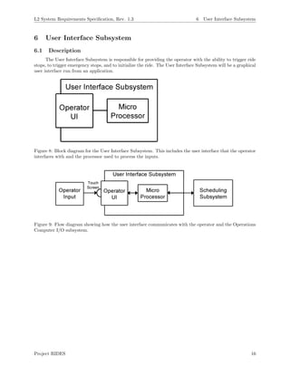
![L2 System Requirements Specification, Rev. 1.3 6 User Interface Subsystem
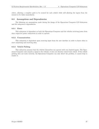
Figure 10: An example user interface that includes options for the operator to start the ride, trigger a ride
stop, and trigger an emergency stop. Grey buttons indicate that the option is disabled. The left side shows
the user interface before the ride has been started. The right side shows the user interface after the ride has
been started. After the ”Init Ride” button is pressed, it is disabled, and the two remaining buttons become
available.
6.2 Constraints
The following are constraints defined by external sources that limit the development of the User Inter-
face Subsystem in accordance with the requirements listed in this document.
6.2.1 Screen Size
The user interface will most likely run on a tablet for portability and ease of use. The average tablet
screen has a height between 7” and 11” and a width between 5” and 7” [5]. A small screen size requires
that only pertinent information to the operator be included in the user interface, so that they can navigate
options easily and perform tasks quickly.
6.3 Assumptions and Dependencies
The following are assumptions made during the design of the user interface and the subsystem’s de-
pendencies.
6.3.1 Platform
The operating system is assumed to be Android because no examples of iOS tablets interfacing with
microcontrollers have been found in the team’s research. This will determine how the application is developed.
Cross-platform development is an option, but may be beyond the scope of this project.
Project RIDES 17](https://image.slidesharecdn.com/65f3553e-d02d-46f7-98d6-0501a7f9d159-160107005120/85/Team-Omni-L2-Requirements-Revised-18-320.jpg)
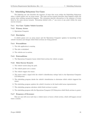
![L2 System Requirements Specification, Rev. 1.3 7 Scheduling Subsystem
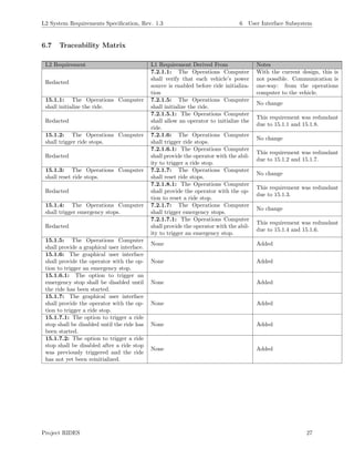
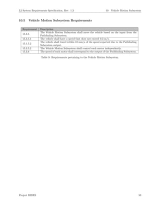
7.7 Traceability Matrix
L2 Requirement L1 Requirement Derived From Notes
15.1.4.1: The Operations Com-
puter shall trigger an emergency
stop if a vehicle, not currently at
a station platform, fails to reach
the end of the currently occupied
block section within 30 s of the
expected time.
7.2.1.7.2: The Operations
Computer shall trigger an emer-
gency stop if a vehicle, not
currently at a station platform,
fails to reach the end of the
currently occupied block sec-
tion within 30 s [TBR] of the
expected time.
No change
15.1.4.2: The expected time
shall be calculated by the Oper-
ations Computer.
7.2.1.7.3: The expected time
shall be determined by the Op-
erations Computer.
”determined” was replaced with
”calculated” because the word
better fits the situation.
15.1.9: The Operations Com-
puter shall direct vehicles out of
the maintenance bay when the
ride is initialized.
7.2.1.2: The Operations Com-
puter shall direct vehicles out of
the maintenance bay when the
ride is initialized.
No change
15.1.11: The Operations Com-
puter shall set the vehicle’s tar-
get location to an effectively un-
occupied block section.
7.2.1.2.1: The Operations
Computer shall set the vehicle’s
target location to an effectively
unoccupied block section.
No change
15.1.13: The Operations Com-
puter shall instruct a vehicle to
the target location of that vehi-
cle.
7.2.1.3: The Operations Com-
puter shall instruct a vehicle to
the target location of that vehi-
cle.
No change
15.1.14: The Operations Com-
puter shall instruct vehicles in
such a way that at least one block
section separates all vehicles.
7.2.1.4: The Operations Com-
puter shall instruct vehicles in
such a way that at least one
block section separates all vehi-
cles when the vehicles are not in
the maintenance bay.
The part of the L1 requirement
that was removed was redun-
dant.
15.1.15: The Operations Com-
puter shall detect the vehicle en-
tering a block section.
7.2.1.10: The Operations Com-
puter shall detect the vehicle en-
tering a block section.
No change
15.1.15.1: The Operations
Computer shall detect which
block section the vehicle is
entering.
7.2.1.10.1: The Operations
Computer shall detect which
block section the vehicle is enter-
ing.
No change
15.1.16: The Operations Com-
puter shall detect the vehicle de-
parting a block section.
7.2.1.9: The Operations Com-
puter shall detect the vehicle ex-
iting a block section.
”exiting” was replaced with ”de-
parting” because the word better
fits the situation.
15.1.16.1: The Operations
Computer shall detect which
block section the vehicle is
departing.
7.2.1.9.1: The Operations
Computer shall detect which
block section the vehicle is
exiting.
”exiting” was replaced with ”de-
parting” because the word better
fits the situation.
15.1.17: The Operations Com-
puter shall track the occupancy
states of all station platforms.
7.2.1.11: The Operations Com-
puter shall track which sta-
tion platforms are occupied and
which are unoccupied.
Changed to be more concise, but
the meaning remains unchanged.
Project RIDES 34](https://image.slidesharecdn.com/65f3553e-d02d-46f7-98d6-0501a7f9d159-160107005120/85/Team-Omni-L2-Requirements-Revised-35-320.jpg)
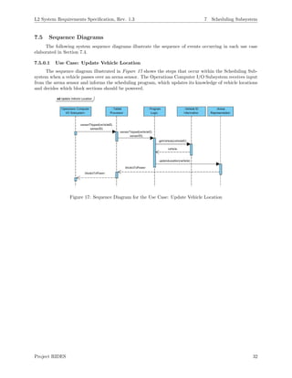
![L2 System Requirements Specification, Rev. 1.3 7 Scheduling Subsystem
15.1.19: The Operations Com-
puter shall stop providing the ve-
hicle with suggested movement
speeds when the vehicle enters a
station platform.
7.2.1.12: The Operations Com-
puter shall stop providing the ve-
hicle with suggested movement
speeds when the vehicle enters a
station platform.
No change
15.1.20: The Operations Com-
puter shall provide a suggested
movement speed to the vehi-
cle with regard to the number
of blocks separating the vehicle
from the vehicle in front of it
along the vehicle’s pathway.
7.2.1.13: The Operations Com-
puter shall provide a suggested
movement speed to the vehi-
cle with regard to the number
of blocks separating the vehicle
from the vehicle in front of it
along the vehicle’s pathway.
No change
15.1.20.1: The Operations
Computer shall provide a sug-
gested movement speed of 0
cm/s for the vehicle when the
vehicle has 1 block section
separating itself and the vehicle
in front of it.
7.2.1.13.1: The Operations
Computer shall provide a sug-
gested movement speed of 0 cm/s
for the vehicle when the vehicle
has 1 block section separating it-
self and the vehicle in front of it.
No change
15.1.20.2: The Operations
Computer shall direct a vehicle’s
movement speed to be less than
5 cm/s when the vehicle has 2
block sections separating itself
and the vehicle in front of it.
7.2.1.13.2: The Operations
Computer shall direct a vehicle’s
movement speed to be less than 5
cm/s [TBR] when the vehicle has
2 block sections separating itself
and the vehicle in front of it.
No change
15.1.20.3:. The Operations
Computer shall direct a vehicle’s
movement speed to be 15 cm/s
when the vehicle has 3 or more
block sections separating itself
from the vehicle in front of it.
7.2.1.13.3: The Operations
Computer shall direct a vehicle’s
movement speed to be 15 cm/s
[TBR] when the vehicle has 3
or more block sections separating
itself from the vehicle in front of
it.
No change
15.1.21: The Operations Com-
puter shall direct the vehicle
with the lower priority level to
decrease its speed when the vehi-
cle is the same number of block
sections behind the PTC switch
as a vehicle on another pathway.
7.2.1.15: The Operations Com-
puter shall direct the vehicle
with the lower priority level to
decrease its speed when the vehi-
cle is the same number of block
sections behind the PTC switch
as a vehicle on another pathway.
No change
15.3.1: The vehicle shall follow
the pathway selected by the Op-
erations Computer.
7.1.1.6: The vehicle shall follow
the pathway selected by the Op-
erations Computer.
No change
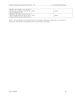
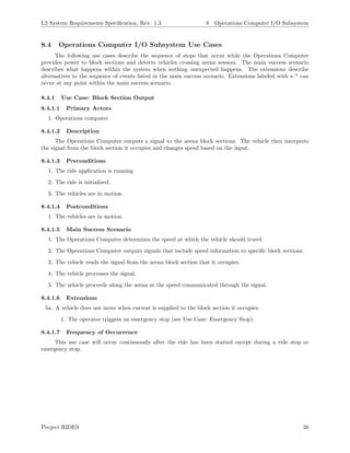
Table 4: The traceability matrix linking each L2 Scheduling Subsystem requirement to its relevant L1
requirement. This includes an explanation of the reason behind each change.
Project RIDES 35](https://image.slidesharecdn.com/65f3553e-d02d-46f7-98d6-0501a7f9d159-160107005120/85/Team-Omni-L2-Requirements-Revised-36-320.jpg)
![L2 System Requirements Specification, Rev. 1.3 9 Wireless Communications Subsystem
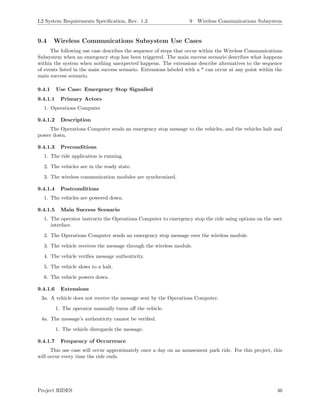
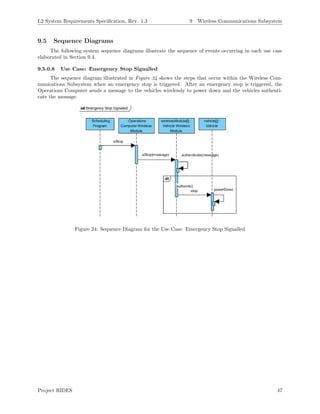
9 Wireless Communications Subsystem
9.1 Description
The Wireless Communications Subsystem is responsible for relaying emergency stop commands from
the Operations Computer to all vehicles on the arena simultaneously. The subsystem consists of a wireless
module or transmitter on the Operations Computer and a wireless module or receiver on each vehicle. The
communication is one-way, and no handshaking is done. This one-way communication is given its own
subsystem to provide a redundant way of stopping vehicle motion. When an emergency stop command is
received on the vehicle side, the power subsystem is disconnected from all other subsystems to stop all vehicle
operation.
Figure 22: Block diagram for the Wireless Communications Subsystem.
Figure 23: Flow diagram showing how the Wireless Communications Subsystem communicates with the
User Interface Subsystem and the Pathfinding Subsystem.
9.2 Constraints
The following are constraints defined by external sources that limit the development of the Wireless
Communications Subsystem in accordance with the requirements listed in this document.
9.2.1 Module Synchronicity
For wireless communication to be executed successfully, the wireless modules on the Operations Com-
puter side and the vehicle side must remain synchronized [6]. The vehicle must sample the incoming signal
at specific instances in time to receive the intended message.
Project RIDES 44](https://image.slidesharecdn.com/65f3553e-d02d-46f7-98d6-0501a7f9d159-160107005120/85/Team-Omni-L2-Requirements-Revised-45-320.jpg)
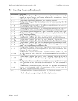
![L2 System Requirements Specification, Rev. 1.3 9 Wireless Communications Subsystem
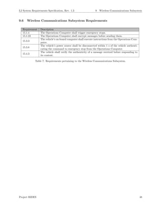
9.7 Traceability Matrix
L2 Requirement L1 Requirement Derived From Notes
15.1.4: The Operations Com-
puter shall trigger emergency
stops.
7.2.1.7: The Operations Com-
puter shall trigger emergency
stops.
No change
15.1.22: The Operations Com-
puter shall encrypt messages be-
fore sending them.
None Added
15.3.3: The vehicle’s on-board
computer shall execute instruc-
tions from the Operations Com-
puter.
7.1.1.9.2: The vehicles’ on-
board computer shall execute in-
structions from the Operations
Computer.
No Change
15.3.8: The vehicle’s power
source shall be disconnected
within 1 s of the vehicle authen-
ticating the command to emer-
gency stop from the Operations
Computer.
7.1.1.3.3: The vehicle’s power
source shall be disconnected
within 1 s [TBR] of the vehicle
receiving the command to emer-
gency stop from the Operations
Computer.
”receiving” was replaced with
”authenticating” because the ve-
hicle shall authenticate the mes-
sage after receiving it and before
processing it.
15.4.3: The vehicle shall verify
the authenticity of a message re-
ceived before executing the in-
structions.
None Added
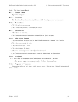
Table 8: The traceability matrix linking each L2 Wireless Communications Subsystem requirement to its
relevant L1 requirement. This includes an explanation of the reason behind each change.
Project RIDES 49](https://image.slidesharecdn.com/65f3553e-d02d-46f7-98d6-0501a7f9d159-160107005120/85/Team-Omni-L2-Requirements-Revised-50-320.jpg)
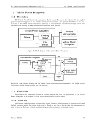
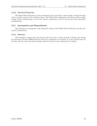
![L2 System Requirements Specification, Rev. 1.3 11 Vehicle Power Subsystem
11.7 Traceability Matrix
L2 Requirement L1 Requirement Derived From Notes
15.3.7: The vehicle’s power
source shall supply DC Power to
all of the vehicle’s systems.
7.1.1.3.1: The vehicle’s power
source shall supply 5 V of DC
power [TBR] to all the vehicle’s
systems.
The requirement was split into
two and the voltage level was re-
fined.
15.3.8: The vehicle’s power
source shall be physically discon-
nected within 1 s of the vehicle
authenticating the command to
emergency stop command.
7.1.1.3.3: The vehicle’s power
source shall be disconnected
within 1 s [TBR] of the vehicle
receiving the command to emer-
gency stop from the operations
computer.
No change needed.
Table 12: The traceability matrix linking each L2 Vehicle Power Subsystem requirement to its relevant L1
requirement. This includes an explanation of the reason behind each change.
Project RIDES 62](https://image.slidesharecdn.com/65f3553e-d02d-46f7-98d6-0501a7f9d159-160107005120/85/Team-Omni-L2-Requirements-Revised-63-320.jpg)
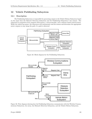
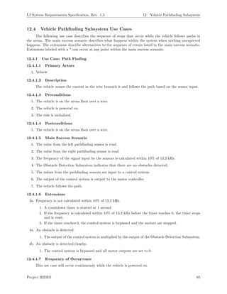
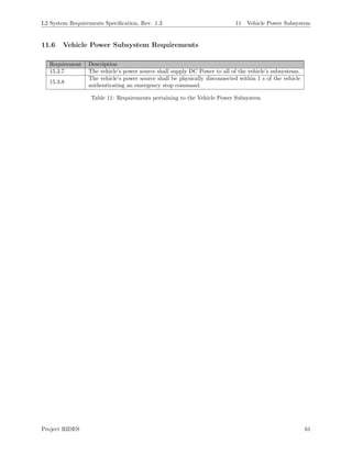
![L2 System Requirements Specification, Rev. 1.3 12 Vehicle Pathfinding Subsystem
12.7 Traceability Matrix
L2 Requirement L1 Requirement Derived From Notes
15.3.4.1: The motor signal out-
put shall direct the vehicle to fol-
low the arena wire.
7.1.1.6: The vehicle shall follow
the pathway selected by the Op-
erations Computer.
The Pathfinding Subsystem has
no direct knowledge of the Op-
erations Computer and is not in
direct control of the motors. The
requirement was updated to re-
flect this.
15.3.4.2: The motor signal out-
put shall be 0 if no clear path is
detected.
None Added
15.3.9: The Pathfinding Sub-
system shall read magnetic field
signals from the arena wire.
None Added
15.3.9.1: Each Pathfinding
Subsystem sensor shall read a
signal from the arena wire when
the sensor is less than 2 cm from
the arena wire.
None Added
15.3.9.2: The Pathfinding Sub-
system sensors shall read a signal
with an amplitude that changes
relative to the inverse of the dis-
tance from the arena wire.
None Added
15.3.10: The Pathfinding Sub-
system shall direct the vehicle
such that the geometric center of
the vehicle is less than 5 cm from
at least 1 point on the arena wire.
7.1.1.6.1: The geometric center
of the vehicle shall deviate from
its current path no more than 5
cm [TBR] on either side of the
vehicles x-axis while moving for-
ward.
The L1 requirement left in too
much ambiguity, the L2 require-
ment can only be fulfilled by
staying on the path, as no two
paths are within 10 cm of each
other.
15.1.10: The Pathfinding Sub-
system shall output one motor
signal to the Vehicle Motion Sub-
system for each motor controlled
by the Vehicle Motion Subsys-
tem.
None Added
15.3.11: The Pathfinding Sub-
system shall accept a value be-
tween 0 to 1 from the Obstacle
Detection Subsystem.
None Added
15.3.11.1: The motor signal
output shall be scaled by the in-
put from the Obstacle Detection
Subsystem.
7.1.1.4: The vehicle shall move
along the vehicle’s positive x-axis
when the vehicle does not detect
an obstruction.
The decomposition of the
Pathfinding Subsystem allowed
for a system that would take
into account all possible outputs
from the Obstacle Detection
Subsystem in one requirement.
Project RIDES 68](https://image.slidesharecdn.com/65f3553e-d02d-46f7-98d6-0501a7f9d159-160107005120/85/Team-Omni-L2-Requirements-Revised-69-320.jpg)
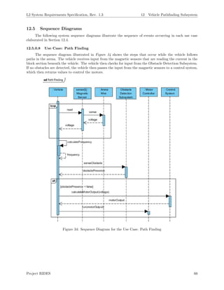
![L2 System Requirements Specification, Rev. 1.3 12 Vehicle Pathfinding Subsystem
15.3.12: The Pathfinding Sub-
system shall calculate the fre-
quency of the signal input by the
magnetic field sensors.
None Added
15.3.12.1: The motor signal
outputs shall be set to 0 within
1 s if the calculated frequency is
not within 10% of the expected
operating value.
7.1.1.7: The vehicle shall re-
main stationary if it does not de-
tect a path.
7.1.1.5: The vehicle shall slow
to a halt within 1 s [TBR] when
the vehicle does not detect a
path.
The frequency of the arena wire
is used to identify the path. The
requirement was updated to re-
flect that system.
Table 14: The traceability matrix linking each L2 Pathfinding Subsystem requirement to its relevant L1
requirement. This includes an explanation of the reason behind each change.
Project RIDES 69](https://image.slidesharecdn.com/65f3553e-d02d-46f7-98d6-0501a7f9d159-160107005120/85/Team-Omni-L2-Requirements-Revised-70-320.jpg)
![L2 System Requirements Specification, Rev. 1.3 15 Project RIDES Requirements
15.1.17 The Operations Computer shall track the occupancy state of each station platforms.
15.1.18 The Operations Computer shall provide a suggested movement speed to the vehicle.
15.1.19 The Operations Computer shall stop providing the vehicle with a suggested movement speed when the
vehicle enters a station platform.
15.1.20 The Operations Computer shall provide a suggested movement speed to the vehicle with regard to the
number of blocks separating the vehicle from the vehicle in front of it along the vehicle’s pathway.
15.1.20.1 The Operations Computer shall provide a suggested movement speed of 0 cm/s to the vehicle
when the vehicle has 1 block section separating itself and the vehicle in front of it.
15.1.20.2 The Operations Computer shall direct a vehicle’s movement speed to be 10 cm/s when the vehicle
has 2 block sections separating itself and the vehicle in front of it.
15.1.20.3 The Operations Computer shall direct a vehicle’s movement speed to be 15 cm/s [TBR] when the
vehicle has 3 or more block sections separating itself from the vehicle in front of it.
15.1.21 The Operations Computer shall direct the vehicle with the lower priority level to decrease its speed
when the vehicle is the same number of block sections behind the PTC switch as a vehicle on another
pathway.
15.1.22 The Operations Computer shall encrypt messages before sending them.
15.2 Operations Computer Non-Functional Requirements
15.2.1 The Operations Computer shall set a vehicle’s target location.
15.2.2 The Operations Computer shall mark a station platform as effectively occupied when a vehicle’s target
location is set to the specified station platform.
15.2.3 The Operations Computer shall mark a block section as effectively occupied when the block section is
a vehicle’s target location.
15.2.4 The Operations Computer shall determine when the vehicle dispatches from the station platform.
15.2.4.1 The vehicle shall remain stationary at the station platform between 30 s to 60 s.
15.2.4.2 The Operations Computer shall check to see if the block sections in front of the vehicle are
unoccupied before instructing the vehicle to leave the station platform.
Project RIDES 83](https://image.slidesharecdn.com/65f3553e-d02d-46f7-98d6-0501a7f9d159-160107005120/85/Team-Omni-L2-Requirements-Revised-84-320.jpg)
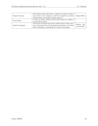
![L2 System Requirements Specification, Rev. 1.3 16 Glossary
16 Glossary
Word Definition Aliases
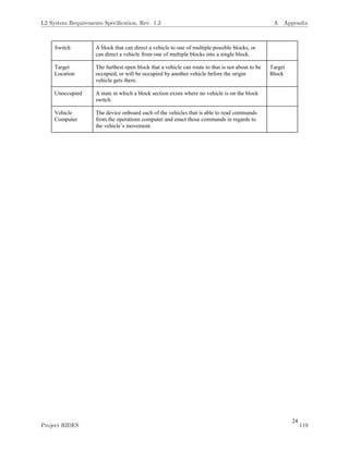
Block Section
A section of path that can safely accommodate a single
vehicle. At no time should a block section contain more
than one vehicle.
Block
Block System
A way of introducing high levels of safety into a ride by
sectioning the ride into block sections.
Effectively Occupied
A state in which a block section exists where the block
section is a vehicle s target location.
Effectively Unoccupied
A state in which a block section exists where the block
section is not the target location of any vehicle.
Emergency Stop
Used to stop the ride in such a manner that the ride will
only operate again with direct intervention from an opera-
tor. Typically, this must be reset by power cycling the ride
[4].
Maintenance Bay
A path or area of a ride on which vehicles can be stored
and worked on.
Moving Block-Light
System
An advanced block system where a vehicle s movement is re-
stricted based on the number of unoccupied blocks separat-
ing itself and the vehicle proceeding it along the path. The
first moving block-light system was introduced for the Walt
Disney World Monorail System known as MAPO (MAry
POppins) [7].
Path
The block sections that are in front of a vehicle between
the vehicle and its target location.
Pathway
A chain of block sections that lead from the STP switch to
the PTS switch.
Pilot Device
A family of related products, including push-buttons, selec-
tor switches, pilot lights, toggle switches, and signal bea-
cons. A pilot device communicates information between
the operator and the machine.
Obstruction
An object that unexpectedly enters a section of path ahead
of the ride vehicle.
Occupied
A state in which a block section exists where a vehicle is
on the block switch.
Operations Computer
The device that monitors the movement and location of all
of the vehicles and the status of each station platform. It
makes decisions regarding vehicle movement based on this
information.
Ride Stop
A function on a ride’s control system that causes all vehicles
to stop and remain stopped until further notice.
Station Area
An area that houses one or more station platforms and a
pathway that vehicles can be directed onto to bypass station
platforms.
Station Platform
A location where vehicles stop to simulate the loading and
unloading of passengers. The vehicles stop there for a
length of time that is based on estimated loading time.
Switch
A block that can direct a vehicle to one of multiple possible
blocks or can direct a vehicle from one of multiple blocks
onto a single block.
Project RIDES 87](https://image.slidesharecdn.com/65f3553e-d02d-46f7-98d6-0501a7f9d159-160107005120/85/Team-Omni-L2-Requirements-Revised-88-320.jpg)
![L2 System Requirements Specification, Rev. 1.3 References
References
[1] Electrical, Computer, Software, and Systems Engineering Department.
(2014, 8 25). ERAU Capstone Design Requirements [Online]. Available:
https://erau.blackboard.com/webapps/blackboard/execute/content
[2] Student Handbook, Embry-Riddle Aeronautical University, Daytona Beach, FL, 2014
[3] ABB Inc., Basic Training, Pilot Devices - 101
[4] Standard Practice for Design of Amusement Rides and Devices, ASTM Standard F2291-14.
[5] Tablet PC Dimensions and Case Sizes. Wikipedia [Online]. Available:
http://en.wikipedia.org/wiki/Tablet PC dimensions and cases sizes
[6] Heidi Steendam et. al, Synchronization in Wireless Communication, EURASIP Journal on Wireless
Communications and Networking 2009, 2009:568369 doi:10.1155/2009/568369
[7] Railroad Accident Brief, National Transportation Safety Board, Washington DC, RAB-11-07, October
31, 2011
Project RIDES 90](https://image.slidesharecdn.com/65f3553e-d02d-46f7-98d6-0501a7f9d159-160107005120/85/Team-Omni-L2-Requirements-Revised-91-320.jpg)
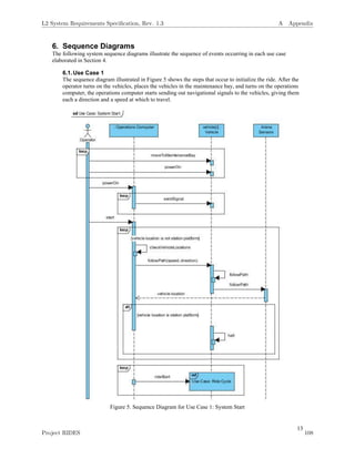
![1
2. Introduction
2.1. Purpose
The purpose of this document is to define the system requirements for Project Ride Integrating
Dynamic Electronic System (RIDES). These requirements include the functional and non-functional
requirements that the vehicles, operations computer, and arena must fulfill upon completion of the
project at the end of the academic year. This document is intended for the consumer of Project RIDES,
the development team of Project RIDES, and all other parties involved with the design, construction,
or maintenance of Project RIDES.
2.2. Mission Statement
To produce a scale mockup of an amusement park ride with multiple autonomous vehicles that operate
simultaneously on converging and diverging pathways within an arena while avoiding collisions.
2.3. Scope
Project RIDES will direct multiple autonomous vehicles along converging and diverging pathways
without colliding in order to reduce operator involvement during ride operations. Ride operations will
instead be controlled by an automated operations computer.
The autonomous system envisioned is a scale mockup of an amusement park ride that will include
multiple vehicles, an operations computer, and an arena. Project RIDES will have multiple pathways
and dynamic speed control with sensors to detect obstructions in the vehicles’ paths. In 2012, 1,424
accidents occurred at amusement parks across the United States. [1]
Amusement park implementation
of the conceptual framework of Project RIDES would help to lower the annual number of accidents by
reducing the responsibilities of ride operators and the number of opportunities for human error.
2.4. Team Information
The following lists the members of the Project RIDES development team and their roles.
Name Role
Jordan Maziarka Scrum Master
Alex Spradlin Software Lead
Andrew Daws Developer
Branden Martin Developer
David Timmons Developer
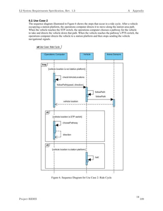
2.5. Overview
This document is organized into sections to effectively communicate the intended functionalities of
Project RIDES and the project’s high-level description.
Section 1 of this document serves to introduce the reader to Project RIDES, describing the scope of the
project and the roles of the development team.
Section 2 provides a high-level description of the project, including the constraints limiting
development, the assumptions made, and the project’s dependencies.
L2 System Requirements Specification, Rev. 1.3 A Appendix
Project RIDES 96](https://image.slidesharecdn.com/65f3553e-d02d-46f7-98d6-0501a7f9d159-160107005120/85/Team-Omni-L2-Requirements-Revised-97-320.jpg)
![5
possession on the ride or needs to have their harness adjusted. The operator can choose to resume
the ride after triggering a ride stop, and the ride will proceed as normal.
Emergency stops are used to stop the ride in such a manner that the ride will only operate again
with direct intervention from an operator. Typically, this must be reset by power cycling the ride.
[2]
The operator can choose to call an emergency stop a danger is present to the riders or one of the
vehicles is not operating. The operations computer can also call an emergency stop it detects one
of these things occurring.
3.3.Constraints
The following are constraints defined by external sources that limit the development of Project RIDES
in accordance with the requirements listed in this document.
3.3.1. Regulation Constraints
Project RIDES is envisioned to be a scale mockup of an amusement park ride that would be used
for the enjoyment of passengers. Therefore, Project RIDES will be developed with consideration
towards the design standards for amusement park rides defined in ASTM F2291-14 that are
unrelated to passengers physically occupying the ride vehicles. [2]
3.3.2. Parallel Operation
The operation of Project RIDES is dependent on the ride vehicles operating in parallel with the
operations computer. After issuing instructions to the ride vehicles, the operations computer
should continue to instruct and monitor each vehicle.
3.3.3. Budget
Project RIDES is funded entirely by the student development team. The financial resources
available to the team are limited to approximately $1000. This constraint limits the development
of Project RIDES to a small number of vehicles unrepresentative of full-scale amusement park
rides and limits the accuracy with which the operations computer tracks the vehicles across block
sections.
3.4.Assumptions and Dependencies
The following are assumptions made during the design of Project RIDES and the project’s
dependencies.
3.4.1. Operation within the United States
This project will adhere to amusement park design standards defined within the United States of
America (USA). Use of Project RIDES outside of the USA would need to conform to the
standards for amusement park rides of that area.
3.5.User Characteristics
As Project RIDES is currently envisioned, a postsecondary education will not be necessary to operate
the system. The operator of Project RIDES will need a general knowledge of amusement park ride
operations, including the high-level sequence of events that occurs during a ride’s operation: a vehicle
loads passengers, the vehicle travels around the ride arena alongside other vehicles, the vehicle unloads
passengers. The operator must also know in what situations ride stops and emergency stops should be
triggered. Project RIDES is a simplified mockup of an amusement park ride, so the situations requiring
either a ride stop or an emergency stop are few in number.
4. Stakeholders
The following are the individuals and groups that are involved in or have an interest in the development
and completion of Project RIDES.
L2 System Requirements Specification, Rev. 1.3 A Appendix
Project RIDES 100](https://image.slidesharecdn.com/65f3553e-d02d-46f7-98d6-0501a7f9d159-160107005120/85/Team-Omni-L2-Requirements-Revised-101-320.jpg)
![6
4.1. Team Omni
Team Omni will be involved in every aspect of the project’s development. As the developers of
Project RIDES, the team shall be graded based on the rigor and difficulty of the project as well as its
progress over the year and ultimately, the project’s completion. The team will apply knowledge of
course content gained throughout their academic careers attending Embry-Riddle Aeronautical
University (ERAU). The team members will be funding the project and are thus interested in
completing it on time and under budget. <deleted>
4.2. Dr. Garfield
As the project’s customer and technical advisor, Dr. Garfield is interested in the completion of project
RIDES. He will be consulted on a weekly basis and will influence all major design decisions.
4.3. Dr. Barott, Dr. Seker, and Jorge Torres
As the overseers of the capstone program, Dr. Barott, Dr. Seker, and Jorge Torres shall be following
the team’s progress and providing guidance throughout the academic year. They will be grading the
team based on their demonstration of the course requirements outlined in the course syllabus. They
will continue to help the team define the scope of the project and will oversee the development
process.
4.4. ERAU
ERAU administrators have an interest in student projects because their level of success reflects on the
institution. To ensure the safety of everyone on campus, ERAU requires that projects adhere to the
standards defined in the 2014-2015 Student Handbook. [3]
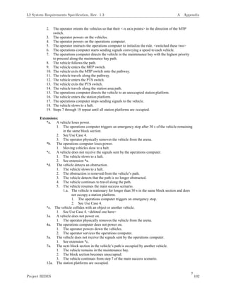
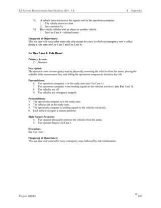
5. Use Cases
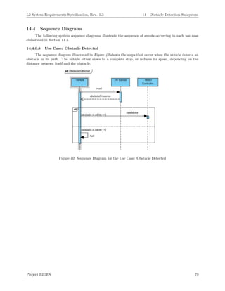
The following use cases describe the sequence of steps that occur when the operator initializes the ride,
triggers a ride stop, or triggers an emergency stop and the steps that occur during a complete ride cycle. The
main success scenario describes what happens within the system when nothing unexpected happens. The
extensions describe alternatives to the sequence of events listed in the main success scenario. The
extensions labeled with a * can occur at any point within the main success scenario.
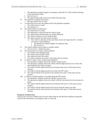
5.1. Use Case 1: Start System
Primary Actors:
1. Operator
Description:
The operator initializes the ride, causing the vehicles to travel along the pathway from the maintenance
bay to the station platforms.
Preconditions:
1. The vehicles are off.
2. The operations computer is off.
Postconditions:
1. The operations computer is in the ready state.
2. The vehicles are in the ready state.
3. The operations computer is sending signals to the vehicles wirelessly.
4. Each vehicle occupies a station platform.
Main Success Scenario:
1. The operator positions the vehicles in the maintenance bay ordered by increasing priority (the
vehicles’ priorities are predefined within the operations computer).
L2 System Requirements Specification, Rev. 1.3 A Appendix
Project RIDES 101](https://image.slidesharecdn.com/65f3553e-d02d-46f7-98d6-0501a7f9d159-160107005120/85/Team-Omni-L2-Requirements-Revised-102-320.jpg)


![17
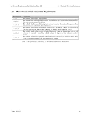
7. Requirements
7.1.Vehicle Requirements
7.1.1.Vehicle Functional Requirements
7.1.1.1. The vehicle shall travel on the floor of the arena.
7.1.1.2. The vehicle shall travel at a speed within 5 mm/s of the speed instructed by
the operations computer when the vehicle does not detect an obstruction.
7.1.1.3. The vehicle shall have a power source.
7.1.1.3.1. The vehicle’s power source shall supply 5V of DC power [TBR]
to all the vehicle’s systems.
7.1.1.3.2. The vehicle’s power source shall be located on the vehicle.
7.1.1.3.3. The vehicle’s power source shall be disconnected within 1 s
[TBR] of the vehicle receiving the command to emergency stop
from the operations computer.
7.1.1.4. The vehicle shall move along the vehicle’s positive x-axis when the vehicle
does not detect an obstruction.
7.1.1.5. The vehicle shall slow to a halt within 1 s [TBR] when the vehicle does not
detect a path.
7.1.1.6. The vehicle shall follow the pathway selected by the operations computer.
7.1.1.6.1. The geometric center of the vehicle shall deviate from its current
path no more than 5 cm [TBR] on either side of the vehicle’s x-
axis while moving forward.
7.1.1.7. The vehicle shall remain stationary if it does not detect a path.
7.1.1.8. The vehicle shall detect obstructions.
7.1.1.8.1. The vehicle shall disregard speed signals received from the
operations computer while the vehicle detects an obstruction.
7.1.1.8.2. The vehicle shall resume following instructions from the
operations computer when the vehicle does not detect the
obstruction.
7.1.1.8.3. The vehicle shall detect obstructions larger than 3 cm x 3 cm x 3
cm within 10 cm [TBR] of the vehicle when the obstruction is
within 10 degrees of the negative x-axis.
7.1.1.8.4. The vehicle shall reduce speed to half of its speed [TBR] when an
obstruction is detected between 10 cm and 3 cm of the vehicle
within 10 degrees [TBR] of the vehicle’s negative x-axis.
L2 System Requirements Specification, Rev. 1.3 A Appendix
Project RIDES 112](https://image.slidesharecdn.com/65f3553e-d02d-46f7-98d6-0501a7f9d159-160107005120/85/Team-Omni-L2-Requirements-Revised-113-320.jpg)
![18
7.1.1.8.5. The vehicle shall reduce speed to a halt when an obstruction is
detected closer than 3 cm within 10 degrees [TBR] of the vehicle’s
negative x-axis.
7.1.1.9. The vehicle shall have an on-board computer.
7.1.1.9.1. The vehicle’s on-board computer shall receive instructions from
the operations computer.
7.1.1.9.2. The vehicle’s on-board computer shall execute instructions from
the operations computer.
7.1.2.Vehicle Non-Functional Requirements
7.1.2.1. RIDES shall have at least 2 vehicles.
7.1.2.1.1. The number of vehicles shall adhere to the following equation, to
avoid section conflicts.
𝑁𝑢𝑛𝑏𝑒𝑟 𝑜𝑓 𝑉𝑒ℎ𝑖𝑐𝑙𝑒𝑠 =
(𝑇𝑜𝑡𝑎𝑙 𝑁𝑢𝑚𝑏𝑒𝑟 𝑜𝑓 𝐵𝑙𝑜𝑐𝑘 𝑆𝑒𝑐𝑡𝑖𝑜𝑛𝑠)−1
3
7.1.2.2. The vehicle shall have a priority level unique amongst the system’s
vehicles.
7.2.Operations Computer Requirements
7.2.1.Operations Computer Functional Requirements
7.2.1.1. The operations computer shall verify that each vehicle’s power source is
enabled before ride initialization.
7.2.1.2. The operations computer shall direct vehicles out of the maintenance bay
when the ride is initialized.
7.2.1.2.1. The operations computer shall set the vehicle’s target location to
an effectively unoccupied block section.
7.2.1.3. The operations computer shall instruct a vehicle to the target location of
that vehicle.
7.2.1.4. The operations computer shall instruct vehicles in such a way that at least
one block section separates all vehicles when the vehicles are not in the
maintenance bay.
7.2.1.5. The operations computer shall initialize the ride.
7.2.1.5.1. The operations computer shall allow an operator to initialize the
ride.
7.2.1.6. The operations computer shall trigger ride stops.
7.2.1.6.1. The operations computer shall provide the operator with the ability
to trigger a ride stop.
L2 System Requirements Specification, Rev. 1.3 A Appendix
Project RIDES 113](https://image.slidesharecdn.com/65f3553e-d02d-46f7-98d6-0501a7f9d159-160107005120/85/Team-Omni-L2-Requirements-Revised-114-320.jpg)
![19
7.2.1.7. The operations computer shall trigger emergency stops.
7.2.1.7.1. The operations computer shall provide the operator with the ability
to trigger an emergency stop.
7.2.1.7.2. The operations computer shall trigger an emergency stop if a
vehicle, not currently at a station platform, fails to reach the end of
the currently occupied block section within 30 s [TBR] of the
expected time.
7.2.1.7.3. The expected time shall be determined by the operations
computer.
7.2.1.8. The operations computer shall reset ride stops.
7.2.1.8.1. The operations computer shall provide the operator with the option
to reset a ride stop.
7.2.1.9. The operations computer shall detect the vehicle exiting a block section.
7.2.1.9.1. The operations computer shall detect which block section the
vehicle is exiting.
7.2.1.10. The operations computer shall detect the vehicle entering a block section.
7.2.1.10.1. The operations computer shall detect which block section the
vehicle is entering.
7.2.1.11. The operations computer shall track which station platforms are occupied
and which are unoccupied.
7.2.1.12. The operations computer shall stop providing the vehicle with suggested
movement speeds when the vehicle enters a station platform.
7.2.1.13. The operations computer shall provide a suggested movement speed to the
vehicle with regard to the number of blocks separating the vehicle from the
vehicle in front of it along the vehicle's pathway.
7.2.1.13.1. The operations computer shall provide a suggested movement
speed of 0 cm/s for the vehicle when the vehicle has 1 block
section separating itself and the vehicle in front of it.
7.2.1.13.2. The operations computer shall direct a vehicle’s movement speed
to be less than 5 cm/s [TBR] when the vehicle has 2 block sections
separating itself and the vehicle in front of it.
7.2.1.13.3. The operations computer shall direct a vehicle’s movement speed
to be 15 cm/s [TBR] when the vehicle has 3 or more block
sections separating itself from the vehicle in front of it.
7.2.1.14. The operations computer shall provide a suggested movement speed for the
vehicle less than 25 cm/s [TBR].
L2 System Requirements Specification, Rev. 1.3 A Appendix
Project RIDES 114](https://image.slidesharecdn.com/65f3553e-d02d-46f7-98d6-0501a7f9d159-160107005120/85/Team-Omni-L2-Requirements-Revised-115-320.jpg)
![20
7.2.1.15. The operations computer shall direct the vehicle with the lower priority
level to decrease its speed when the vehicle is the same number of block
sections behind the PTC switch as a vehicle on another pathway.
7.2.2.Operations Computer Non-Functional Requirements
7.2.2.1. The operations computer shall set a vehicle’s target location.
7.2.2.2. The operations computer shall mark a station platform as effectively
occupied when a vehicle’s target location is set to the specified station
platform.
7.2.2.3. The operations computer shall mark a block section as effectively occupied
when the block section is another vehicle’s target location.
7.2.2.4. The operations computer shall select an initial target location for each
vehicle.
7.2.2.4.1. The operations computer shall initiate cycling when all the
vehicles arrive at their respective target locations.
7.2.2.5. The operations computer shall determine when the vehicle dispatches from
the station platform.
7.2.2.5.1. The vehicle shall remain stationary at the station platform between
30 s to 60 s [TBR].
7.2.2.5.2. The operations computer shall check to see if the block sections in
front of the vehicle are unoccupied before instructing the vehicle
to leave the station platform.
7.3.Arena Requirements
7.3.1.Arena Non-Functional Requirements
7.3.1.1. The arena shall have a floor consisting of ¾ inch plywood [TBR] with
dimensions 200 cm x 200 cm x 20 cm [TBR].
7.3.1.2. The course shall have at least 2 pathways.
7.3.1.2.1. Each pathway shall be composed of at least 3 block sections.
7.3.1.2.2. Each block section shall end at the start of another block section.
7.3.1.2.3. Each block section shall be no shorter in length than a vehicle.
7.3.1.3. The course shall have a maintenance bay.
7.3.1.3.1. The maintenance bay shall be comprised of at least 2 block
sections [TBR].
7.3.1.3.2. The maintenance bay shall be connected to the MTP switch.
7.3.1.3.3. The maintenance bay shall be connected to the STP switch.
L2 System Requirements Specification, Rev. 1.3 A Appendix
Project RIDES 115](https://image.slidesharecdn.com/65f3553e-d02d-46f7-98d6-0501a7f9d159-160107005120/85/Team-Omni-L2-Requirements-Revised-116-320.jpg)

![22
8. References
[1] National Safety Council Research and Statistical Services Group.(August 2013).
FIXED-SITE AMUSEMENT RIDE INJURY SURVEY, 2012 UPDATE [Online]. Available:
http://www.nsc.org/news_resources/injury_and_death_statistics/Documents/Injury-Facts-
Report.pdf
[2] Standard Practice for Design of Amusement Rides and Devices, ASTM Standard F2291-14.
[3] Student Handbook, Embry-Riddle Aeronautical University, Daytona Beach, FL, 2014
[4] “Railroad Accident Brief”,National Transportation Safety Board, Washington DC, RAB-11-07, October
31, 2011
L2 System Requirements Specification, Rev. 1.3 A Appendix
Project RIDES 117](https://image.slidesharecdn.com/65f3553e-d02d-46f7-98d6-0501a7f9d159-160107005120/85/Team-Omni-L2-Requirements-Revised-118-320.jpg)
![23
9. Glossary
Word Definition Aliases
Block Section A section of path that can safely accommodate a single vehicle. At no
time should a block ever contain more than one vehicle.
Block System A way of implementing high levels of safety into a ride by sectioning the
ride into block sections.
Effectively
Occupied
A state in which a block section exists where the block section is a
vehicle’s target location.
Effectively
Unoccupied
A state in which a block section exists where the block section is not the
target location of any vehicle.
Emergency
Stop
Used to stop the ride in such a manner that the ride will only operate
again with direct intervention from an operator. Typically, this must be
reset by power cycling the ride .[2]
E-Stop
Maintenance
Bay
A path or area in a ride on which vehicles can be stored and worked on.
Moving Block-
Light System
A more advanced version of a block system where a vehicle’s movement
is restricted based on the number of unoccupied blocks separating itself
and the vehicle in front of it. Vehicles halt in this system when one block
separates itself and the vehicle in front of it. The first moving block-light
system was introduced by the Walt Disney Company for use on the Walt
Disney World Monorail System, whereas it is known as MAPO (MAry
Poppins).[4]
Path The block sections that are in front of a vehicle between the vehicle and
its target location.
Pathway A chain of block sections that lead from the STP switch to the PTS
switch.
Obstruction An object that enters in front of the ride vehicle unexpectedly.
Occupied A state in which a block section exists where a vehicle is on the block
switch.
Operations
Computer
The device that monitors the movement and location of all of the
vehicles and the station platforms’ statuses and makes decisions
regarding vehicle movement based on this information.
Ride
Computer
Ride Stop A function on a ride’s control system that causes all vehicles to stop at
and remain as so until further notice.
Station Area An area that houses one or multiple station platforms and a pathway that
vehicles can be directed on to bypass the station platforms.
Station
Platform
A location where vehicles stop to simulate the loading and unloading of
passengers. The vehicles pause for a certain amount of time based on
estimated loading time.
L2 System Requirements Specification, Rev. 1.3 A Appendix
Project RIDES 118](https://image.slidesharecdn.com/65f3553e-d02d-46f7-98d6-0501a7f9d159-160107005120/85/Team-Omni-L2-Requirements-Revised-119-320.jpg)


![Xadrez ap..[1]](https://cdn.slidesharecdn.com/ss_thumbnails/xadrezap-150104073444-conversion-gate01-thumbnail.jpg?width=640&height=640&fit=bounds)