Downloaded 53 times

![1 INTRODUCTION page 3
1 Introduction
This document is a hardware and software guide for Silabs devices and the Wireless M-Bus Stack from Steinbeis
Transfer Center Embedded Design and Networking [STZEDN] and describes the installation of Wireless M-Bus devices
to test, to evaluate and to configure with the Wireless M-Bus Suite.
The guide contains the following chapters:
• Chapter 5.1: System Requirements
This chapter specifies the system requirements for the PC to use the Wireless M-Bus Suite for 32-Bit and 64-Bit
operating systems.
• Chapter 5.2: COM Port Settings
This chapter contains the required settings to connect the target hardware to the PC.
• Chapter 4: Hardware Setup and Firmware Installation
This chapter describes the hardware setup, defines performance and peripheral information and specifies dif-
ferent ways to upload the Wireless M-Bus Stack from STZEDN for each Silabs microcontroller family.
• Chapter 5: Wireless M-Bus Suite Quick Start Guide
The Wireless M-Bus Suite quick start guide leads the user step by step through the included demo configuration
to setup a Wireless M-Bus network in a fast and easy way.
The Wireless M-Bus Suite from STZEDN is a computer program to test, to evaluate and to configure Wire-
less M-Bus devices running the Wireless M-Bus Stack. It contains mechanisms to build up a Wireless M-Bus
network. It provides interfaces to control the different device types of the Wireless M-Bus Stack - collector,
meter and protocol monitor (Wireless M-Bus sniffer). The Wireless M-Bus Suite is designed to handle different
network configurations. Configurations can easily be changed, updated or stored. Furthermore it is capable
to run Wireless M-Bus devices with different parameters and settings (e.g. security, device addresses, uni- or
bidirectional).
The Wireless M-Bus Suite uses a serial interface to communicate with the Wireless M-Bus devices and is able
to upload a new firmware image to a Wireless M-Bus device.
• Chapter 6: Wireless M-Bus Protocol Monitor
The Wireless M-Bus Protocol Monitor is an integrated application in the Wireless M-Bus Suite. It is a Wireless
M-Bus Sniffer and can be used to monitor Wireless M-Bus packets. Besides meter and collector configura-
tions, the Wireless M-Bus Stack from STZEDN contains configurations is capable of Wireless M-Bus Sniffer
configurations.
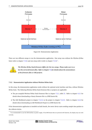
• Chapter 7: Demonstration Application
This chapter presents the demonstration application of the Wireless M-Bus Stack with a sample experimenter
Quick Start Guide
Version 1.02](https://image.slidesharecdn.com/wireless-m-bus-quick-start-guide-140601005119-phpapp02/85/Wireless-m-bus-quick-start-guide-3-320.jpg)
![2 WIRELESS M-BUS BASICS page 11
2 Wireless M-Bus Basics
2.1 Introduction
The Metering Bus (or in short "M-Bus ") is a field bus specialized for transmission of metering data from gas, electricity,
heat, water or other meters to a data collector. It is described by European Norm (EN 13757), which includes the
specification of wired and Wireless M-Bus. The specification is divided into five parts:
• EN 13757-1 ([1]):
Communication systems for meters and remote reading of meters - Part 1: Data exchange
The first part describes the basic communication between the meters and a central data collector. It provides
an overview of the communication system.
• EN 13757-2 ([2]):
Communication systems for meters and remote reading of meters - Part 2: Physical and link layer
The second part includes the specification of the physical data transmission using wired connections. It also
includes the description of the protocol to transmit the data.
• EN 13757-3 ([3]):
Communication systems for meters and remote reading of meters - Part 3: Dedicated application layer
The third part describes a standardized application protocol to enable multivendor capability. So devices of
different manufacturers may be combined in one system.
• EN 13757-4 ([4]):
Communication systems for meters and remote reading of meters - Part 4: Wireless meter readout (Radio me-
ter reading for operation in the 868 MHz to 870 MHz SRD band)
This part specifies the wireless communication of M-Bus and is the main source document for this implemen-
tation. It includes the Physical and the Data Link Layer for wireless devices. It corresponds to specification EN
13757-2 for wired communication.
• EN 13757-5 ([5]):
Communication systems for meters and remote reading of meters - Part 5: Relaying
This last part includes different proposals for relaying data frames to overcome the range problem between
remote meters and data collectors.
The sixth part of this norm relates only to wired busses and is disregarded in this document.
All parts of EN 13757 are compliant to the European Norm EN 870-5 [6].
Quick Start Guide
Version 1.02](https://image.slidesharecdn.com/wireless-m-bus-quick-start-guide-140601005119-phpapp02/85/Wireless-m-bus-quick-start-guide-11-320.jpg)
![2 WIRELESS M-BUS BASICS page 12
2.2 Protocol Stack
2.2.1 Introduction
M-Bus is compatible to the international ISO/OSI-model, but only the layers 1, 2 and 7 are implemented.
Layer 7 Application Layer (EN 13757-3)
Layer 2 Data Link Layer (EN 13757-2 or EN 13757-4)
Layer 1 Physical Layer (EN 13757-2 or EN 13757-4)
Table 3: Operating Modes of Wireless M-Bus
Up to now, the application layer implements all other protocol layers required for a specific appliance. Especially
if routing is required according to [5], it is implemented in the application layer. The reduced modularity leads
to compact implementations running on very small devices with minimum computing resources. But the lack of
modularity certainly is one of the reasons why standardized routing protocols are currently not available for Wireless
M-Bus. The M-Bus favours asymmetric network topologies with low-cost or low-power metering devices on the one
side and data collectors or gateways with higher performance on the other side. Currently, only point-to-point or
star network topologies can be supported. Mesh or multi-hop topologies are not possible. This chapter describes the
settings for implementations of the data collector and the metering devices to setup a network in star topology.
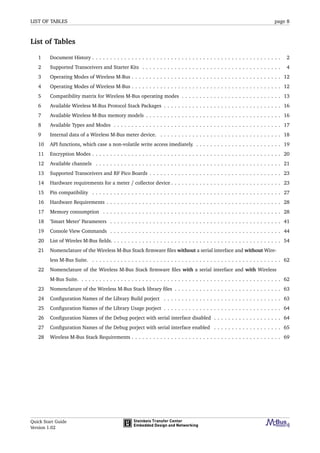
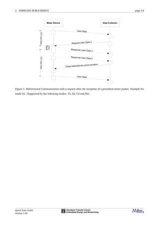
2.2.2 Communication Modes
Dependly on the application there are various combinations of communication modes for data collectors and metering
devices. These settings define the communication flow and the configuration of the radio channel. Table 4 lists
available communication modes.
Mode Communication Description
S1 Unidirectional In the stationary mode, the metering devices send their data several times a day.
In this mode, the data collector may save power as the metering devices send a
wakeup signal before transmitting their data.
S2 Bidirectional Bidirectional version of S1.
T1 Unidirectional In the Frequent Transmit mode, the metering devices periodically send their data
to collectors in range. The interval is configurable in terms of several seconds or
minutes.
T2 Bidirectional Bidirectional version of T1. The data collector may request dedicated data from
the metering devices.
C1 Unidirectional "Compact Mode" mode. This mode is similar to mode T but it allows for transmis-
sion of more data within the same energy budget and with the same duty cycle. It
is suitable for walk-by and/or drive-by readout. The common reception of mode T
and mode C frames with a single receiver is possible.
C2 Bidirectional Bidirectional version of C1. The data collector may request dedicated data from
the metering devices.
Table 4: Operating Modes of Wireless M-Bus
Table 5 lists the combinations of the communication modes of meters and data collectors.
Quick Start Guide
Version 1.02](https://image.slidesharecdn.com/wireless-m-bus-quick-start-guide-140601005119-phpapp02/85/Wireless-m-bus-quick-start-guide-12-320.jpg)
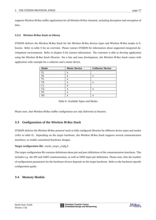
![3 THE STZEDN PROTOCOL STACK page 15
3 The STZEDN Protocol Stack
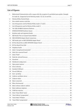
3.1 Wireless M-Bus Protocol Stack
The Wireless M-Bus Stack from STZEDN is a fully Wireless M-Bus complicant protocol stack, including OMS v.3.0.1
[7]. It implements the functionality described in EN-13757 ([1], [2], [3], [4], [5]). Refer to figure 2 for a graphical
overview.
Figure 2: Wireless M-Bus Protocol Stack
The Wireless M-Bus protocol stack from STZEDN basically consists of four different parts:
• Wireless M-Bus Stack:
The Wireless M-Bus Stack part of the protocol stack contains all Wireless M-Bus functionality.
• Hardware drivers:
This part of the protocol stack contains all low level drivers to control the microcontroller unit, such as com-
munication interfaces, memory resources and pheripheral units.
• Utility Module:
This part of the protocol stack contains mechanisms and functions which the stack uses to forward information
through the protocol layers, to report runtime information, to handle time intervals and clocks, to manage
meterlists and to execute software updates.
Quick Start Guide
Version 1.02](https://image.slidesharecdn.com/wireless-m-bus-quick-start-guide-140601005119-phpapp02/85/Wireless-m-bus-quick-start-guide-15-320.jpg)

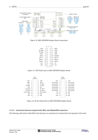
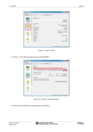
![4 SETUP page 29
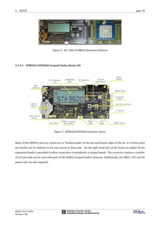
4.2.1 Firmware Installation with Simplicity Studio
To install a firmware using Simplicity Studio the following steps must be performed.
1. Connect the mini USB port of the target board to your PC using a mini USB cable (J-Link interface)
2. Connect the micro USB port of the target board to your PC using a micro USB cable (serial interface).
3. Open the Simplicity Studio software (Studio software [8]).
Figure 14: Simplicity Studio
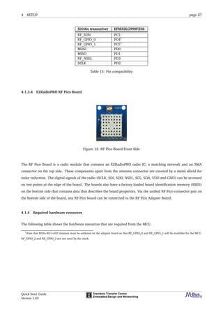
4. Select "energyAwareCommander"
Quick Start Guide
Version 1.02](https://image.slidesharecdn.com/wireless-m-bus-quick-start-guide-140601005119-phpapp02/85/Wireless-m-bus-quick-start-guide-29-320.jpg)
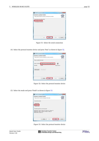
![5 WIRELESS M-BUS SUITE page 41
Parameter Purpose
Device address Address of the ’Smart Meter’.
Collector address Address of the ’Data Collector’, to which
the ’Smart Meter’ sends data.
Encryption key The key encrypts the Wireless M-Bus
wireless telegrams.
Binding information This checkbox sets the ’Smart Meter’ to
the connected state.
Time interval The time interval [ms] of periodical data.
Table 18: ’Smart Meter’ Parameters
The ’Smart Meter’ meter will send messages in the configured time interval. The ’Set binding information’ checkbox
is used to set manual connections. Please refer to the manual of the Wireless M-Bus Suite for detailed information
regarding this attribute.
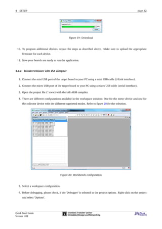
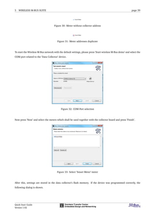
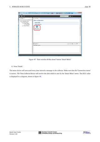
To start the network using the default settings, please press ’Start wireless M-Bus demo’, select the COM port related
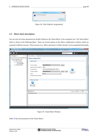
to the ’Smart Meter’ device. (refer to figure 32). Then press ’Finish’ and the device will be programmed. If the device
was programmed correctly, the following dialog is shown.
Figure 36: ’Smart Meter’ programmed
In the demo project, the ’Smart Meter’ sends a default packet to the collector every 10 seconds.
5.6 Using the Wireless M-Bus Suite
This chapter describes specific device configurations and special functions of the Wireless M-Bus Suite.
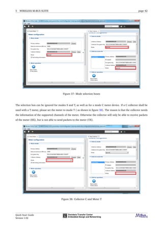
5.6.1 Mode selection
The ’Data Collector’ and the ’Smart Meter’ window includes a ’Mode’ selection box. The Wireless M-Bus mode can
be selected here. The selection of the mode is necessary only in case of mode C or mode N. The following picture
shows the mode selection boxes.
Quick Start Guide
Version 1.02](https://image.slidesharecdn.com/wireless-m-bus-quick-start-guide-140601005119-phpapp02/85/Wireless-m-bus-quick-start-guide-41-320.jpg)
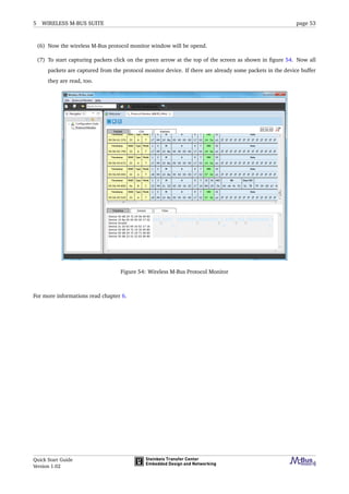
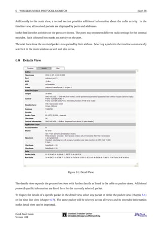
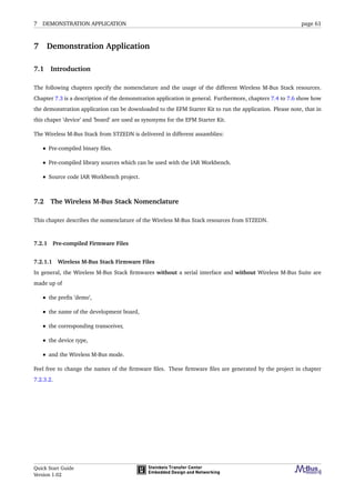
![6 WIRELESS M-BUS PROTOCOL MONITOR page 54
6 Wireless M-Bus Protocol Monitor
6.1 Introduction
This document covers instructions for the use of wireless M-Bus protocol monitor. The first chapter contains the
specifications of the wireless M-Bus protocol monitor. A quick start guide follows, that describes in short terms how
to get the protocol monitor into operation for the first time. In the third part, the web interface, being the main user
interface, is described. Especially focussing on the different views of captured data.
6.2 Wireless M-BUS protocol
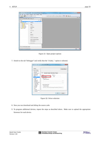
A Wireless M-Bus packet consists of several blocks. The first block contains 12 bytes, the following blocks may contain
up to 16 bytes. For each block, a 16 bit wide checksum of the current block is transmitted (2 bytes).
Name Size (Byte) Description
Length (L) 1 Number of packet bytes excluding
the length field and all CRCs.
Type (C) 1 Packet type.
Manufacturer Id (M) 2 ID of the manufacturer, according
to DLMS.
Type (A) 6 Address of the meter device.
Checksum (CRC) 2 Checksum of the current block.
Application Type (CI) 1 Type field of the application layer.
(Application Layer) x Data of the application layer
Table 20: List of Wireles M-Bus fields.
Figure 55: Example of a Wireless M-Bus packet.
This document assumes that the reader is familiar with the Wireless M-Bus specification, according to EN 13757 [9]
and its application layer extensions of Open Metering System (OMS) [10] and the Dutch Smart Meter Requirements
(DSMR). Otherwise, please contact STZEDN [11] for further documentation or training.
Quick Start Guide
Version 1.02](https://image.slidesharecdn.com/wireless-m-bus-quick-start-guide-140601005119-phpapp02/85/Wireless-m-bus-quick-start-guide-54-320.jpg)
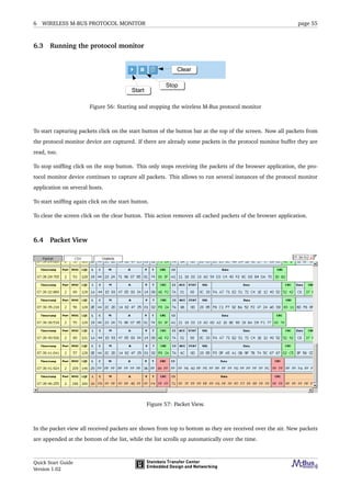
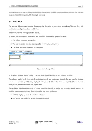
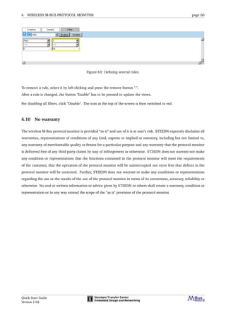
![6 WIRELESS M-BUS PROTOCOL MONITOR page 57
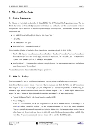
6.6 Statistics View
Figure 59: Statistic View.
The statistics view is used to group packets. Packets with the same field values can be set up as statistic to get the
overall count of the number of packets.
To create a group select the field of the drop down list in the header row and click on "Add group". Now all packets
are grouped by this field. To add further groups repeat this step.
To remove a grouping field, click on the red x behind the field value of "Grouped by" line.
The grouped packets are shown as tree view. If several groups are chosen, click on the [+] in front of the group name
to display the subgroups of the current group. For faster opening or closing all groups click on the button "Expand
all" or "Collapse all".
The statistics view works independently of the other views. If all packets of the views cleared by pressing the clear
button, the packets in the statistic are kept. Click on the button "Clear statistic" to clear the packets from the statistic
view.
6.7 Timeline View
Figure 60: Timeline View.
Quick Start Guide
Version 1.02](https://image.slidesharecdn.com/wireless-m-bus-quick-start-guide-140601005119-phpapp02/85/Wireless-m-bus-quick-start-guide-57-320.jpg)
![REFERENCES page 71
References
[1] “Communication systems for meters and remote reading of meters.” Part 1: Data exchange; English version EN
13757-1, 2002.
[2] “Communication systems for meters and remote reading of meters.” Part 2: Physical and link layer; English
version EN 137572, 2004.
[3] “Communication systems for meters and remote reading of meters.” Part 3: Dedicated application layer; English
version EN 137573, 2004.
[4] “Communication systems for meters and remote reading of meters.” Part 4: Wireless meter readout (Radio
meter reading for operation in the 868 MHz to 870 MHz SRD band); German version EN 137574, 2005.
[5] “Communication systems for meters and remote reading of meters.” Part 5: Wireless Relaying; English version
prEN 13757-5, 2009.
[6] “Telecontrol equipment and systems.” Part 5: Transmission protocols; EN 870-5, 2002.
[7] “Open metering system specification - volume 2: Primary communication.” http://www.oms-
group.org/download/OMS-Spec_Vol2_Primary_v301.pdf, 2011.
[8] S. Labs, “Simplicity studio homepage, "http://www.energymicro.com/software/simplicity-studio".”
[9] “European committee for standardization.” [Online; accessed 15-December-2011] http://www.cen.eu.
[10] “Oms-group.” [Online; accessed 15-December-2011] http://www.oms-group.org.
[11] “Steinbeis transfer center for embedded design and networking.” [Online; accessed 15-December-2011]
http://www.stzedn.de.
Quick Start Guide
Version 1.02](https://image.slidesharecdn.com/wireless-m-bus-quick-start-guide-140601005119-phpapp02/85/Wireless-m-bus-quick-start-guide-71-320.jpg)

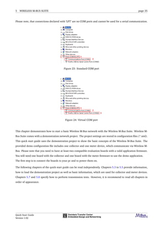
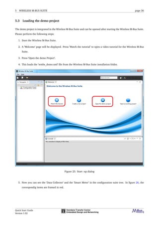
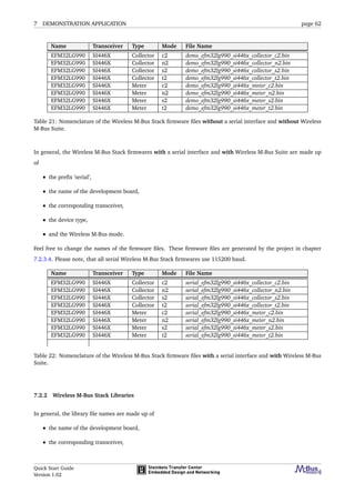
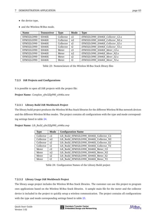
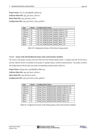
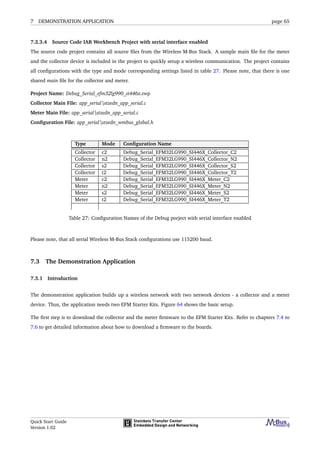
This document provides instructions for setting up and using Wireless M-Bus devices with the Wireless M-Bus Suite software. It describes the hardware and firmware setup, including supported radio modules, required resources, and how to install firmware. It also provides a quick start guide for using the Wireless M-Bus Suite to test devices, including how to set the COM port, load a demo project, use the collector and meter modes, and perform tests like pinging. Additional chapters cover the Wireless M-Bus protocol monitor for analyzing network packets and a demonstration application.


