Download to read offline
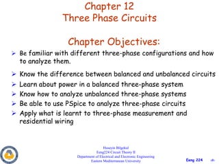
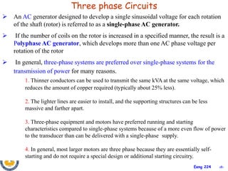
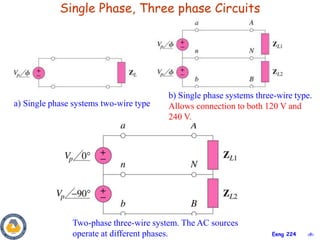
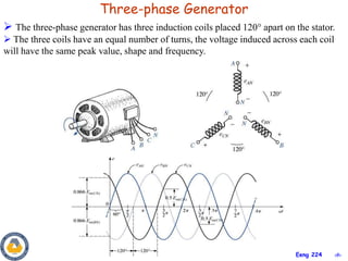
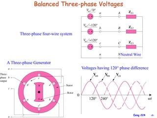
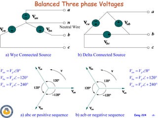
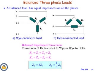
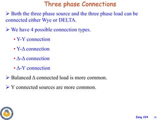
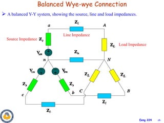
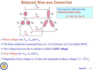
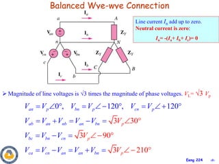
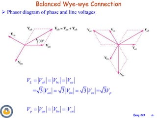
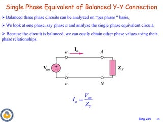
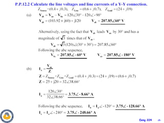
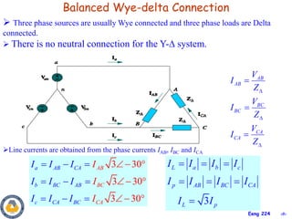
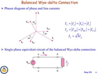
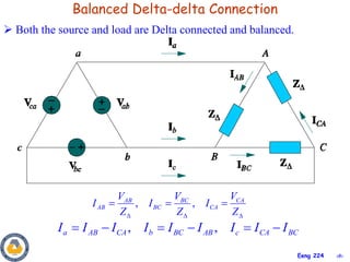
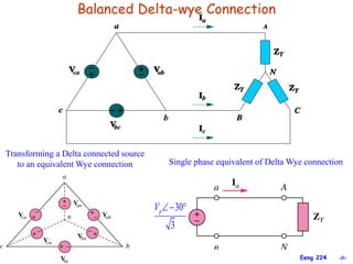

This document provides an overview of key concepts in three-phase circuits. It discusses different three-phase configurations including wye, delta, and their combinations. Balanced and unbalanced three-phase systems are examined. The objectives are to understand how to analyze three-phase circuits, distinguish between balanced and unbalanced systems, apply concepts to power calculations and measurements, and simulate three-phase circuits in PSpice. Diagrams demonstrate voltage and current relationships in various three-phase connections.