Download to read offline
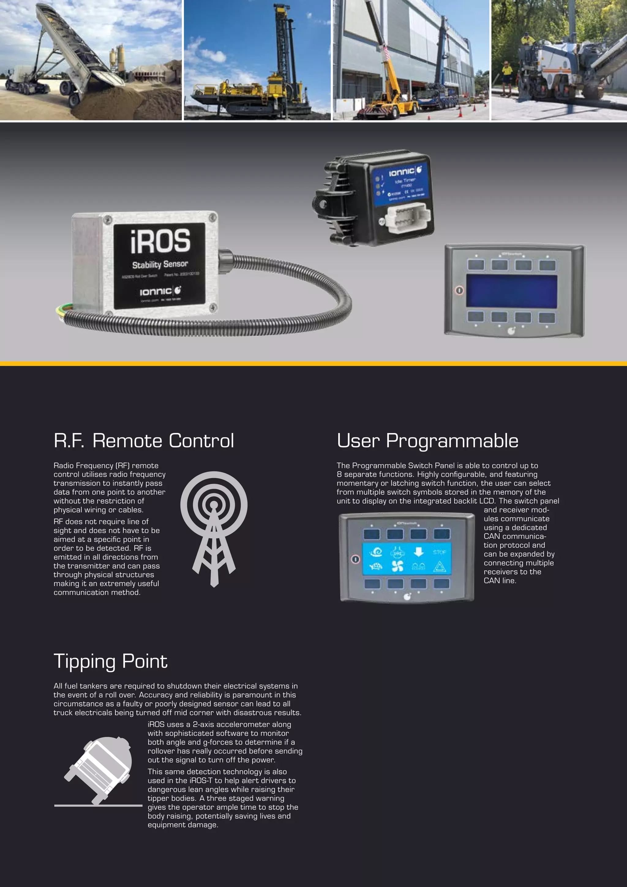
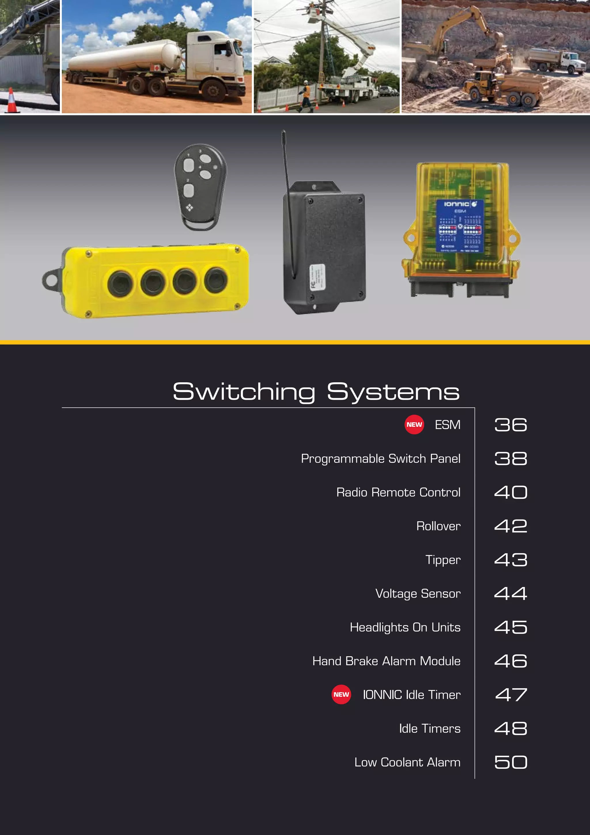
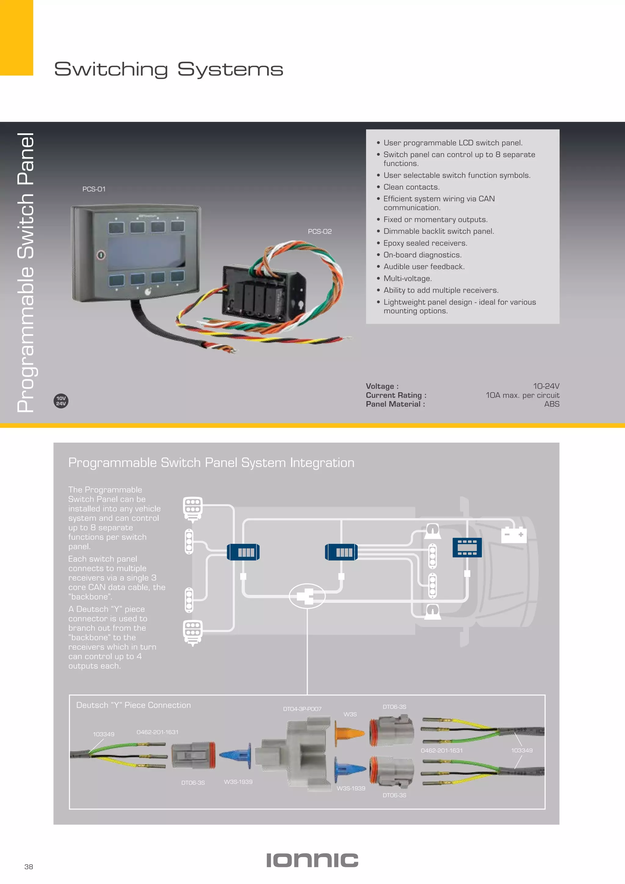
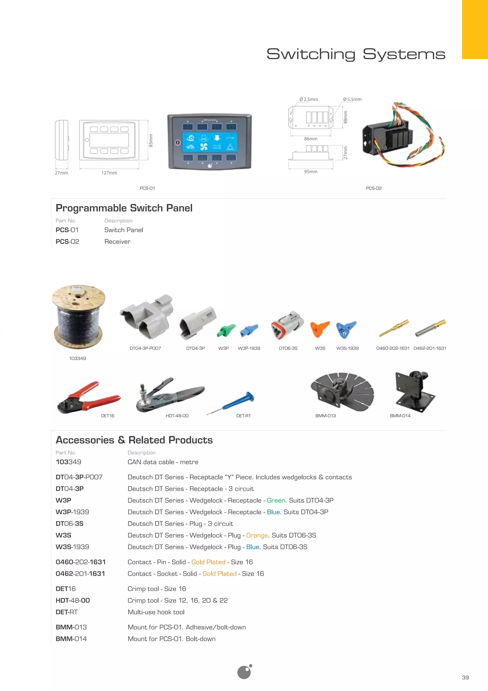
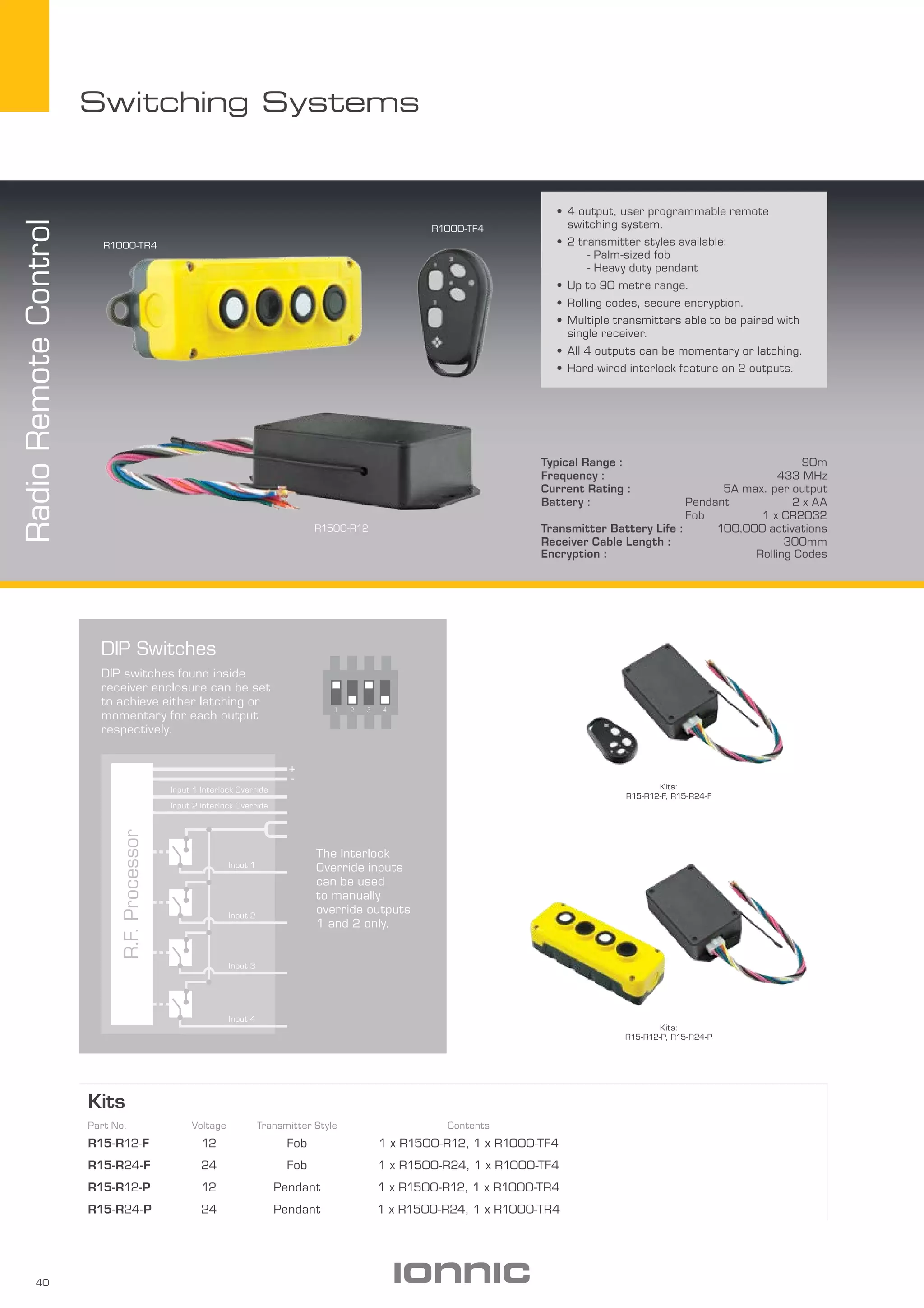
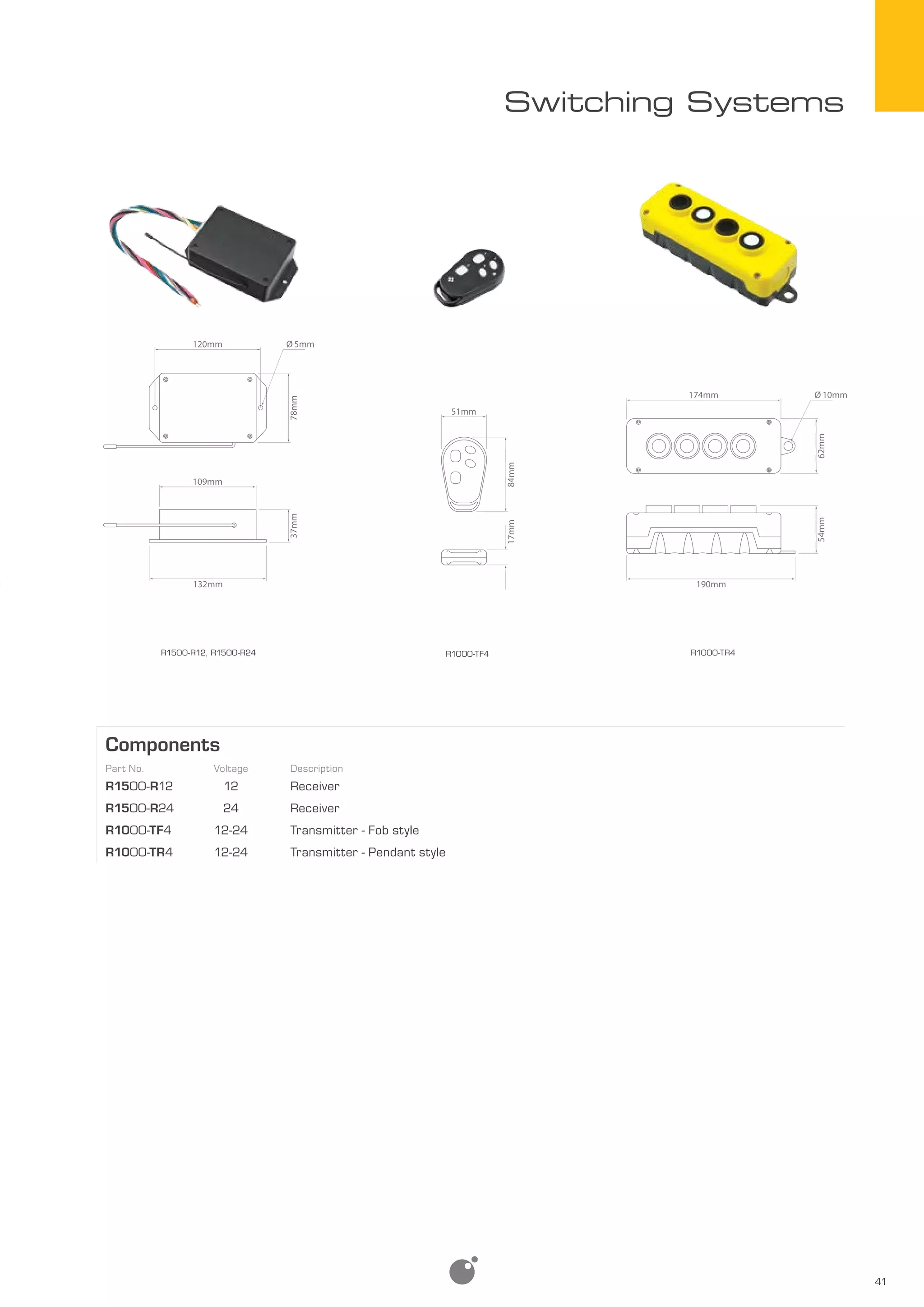
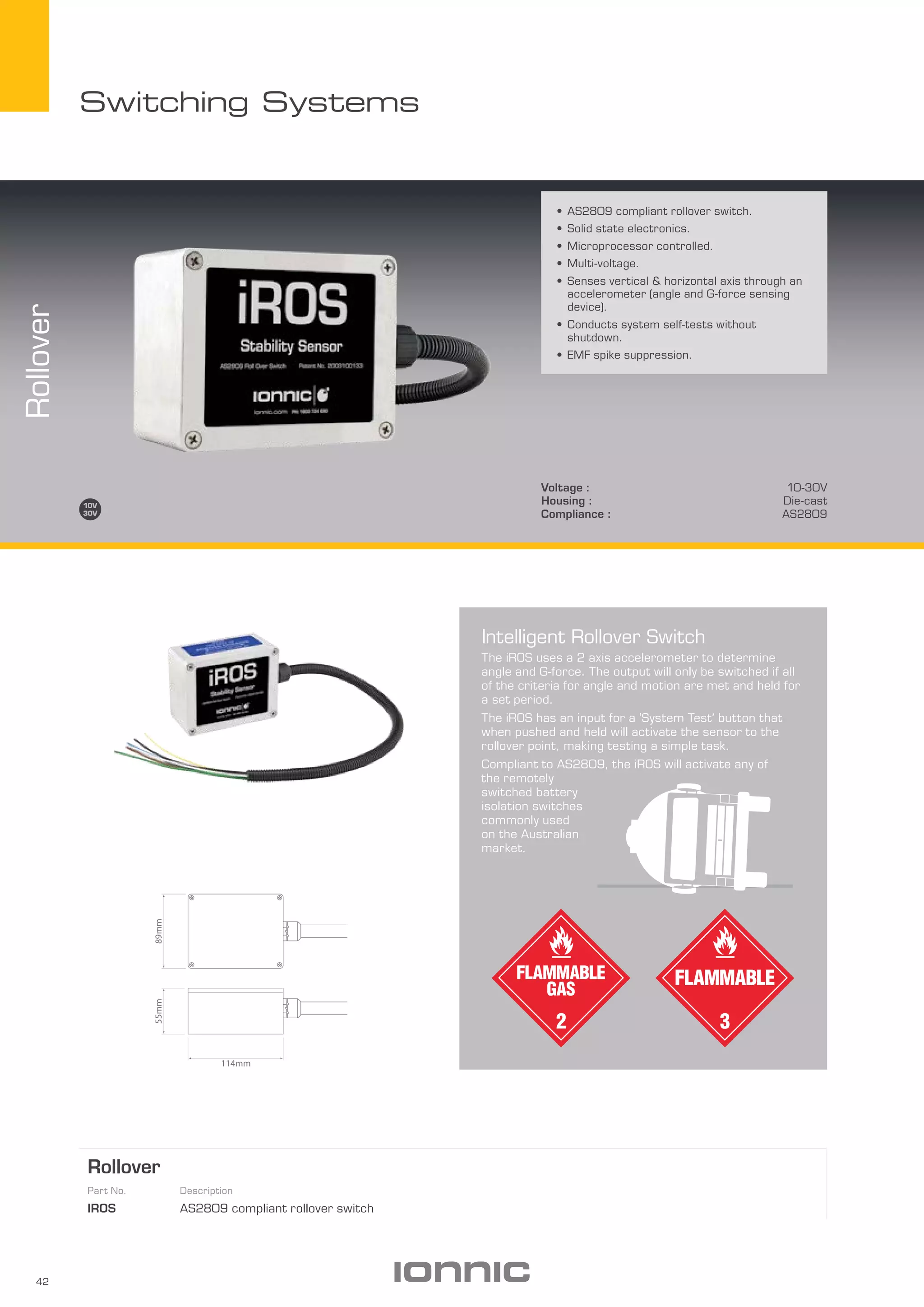
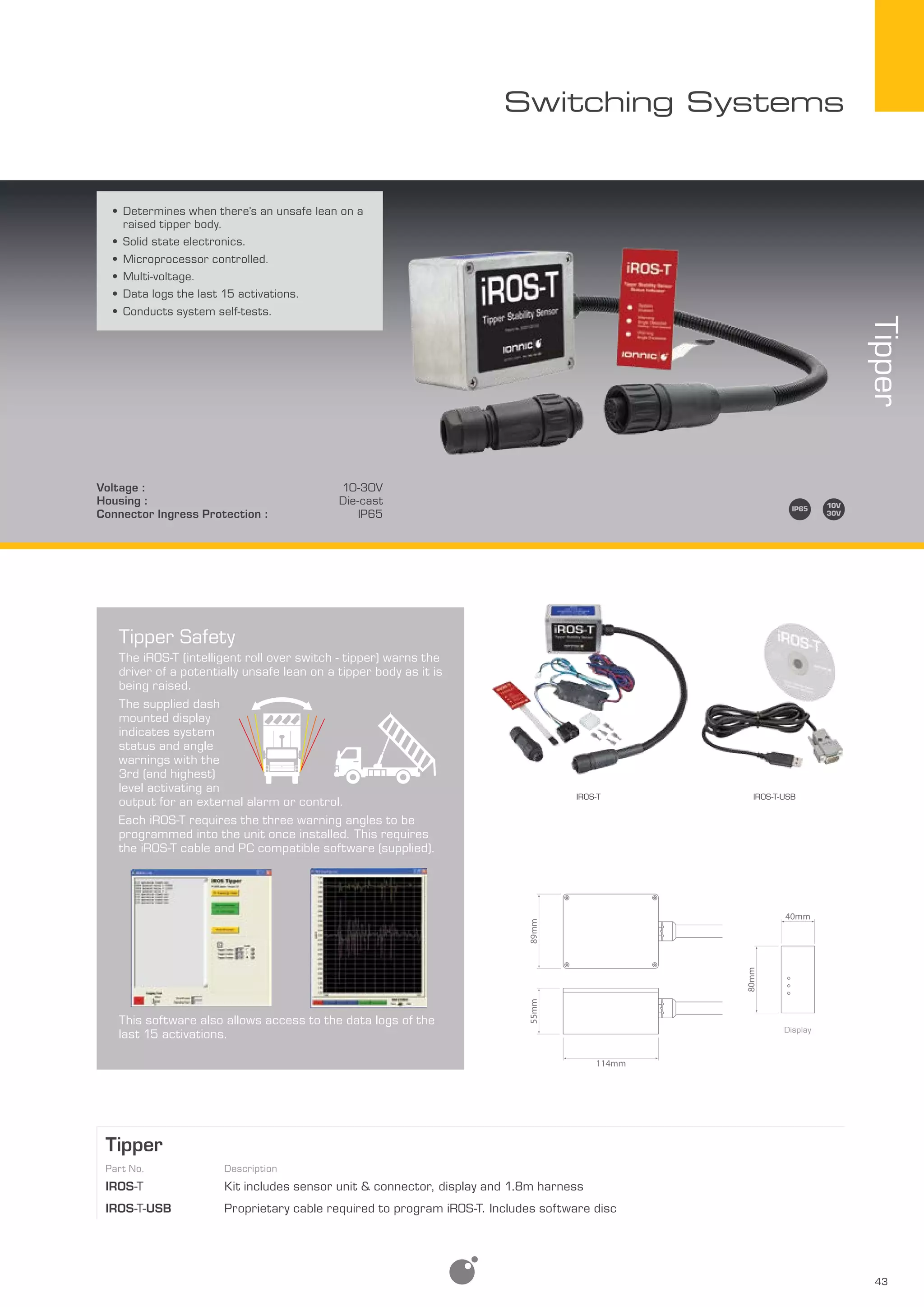

The document discusses several technologies for remote control and safety applications: (1) RF remote control uses radio frequencies to transmit data without wires over long distances and through structures. (2) The iROS rollover sensor uses an accelerometer to accurately detect if a vehicle has rolled over before shutting down electrical systems, as required by regulations. (3) The programmable switch panel allows remote control of multiple functions through an LCD interface and CAN bus communication between devices.


