Downloaded 73 times


![Outdoor current and voltage transformers
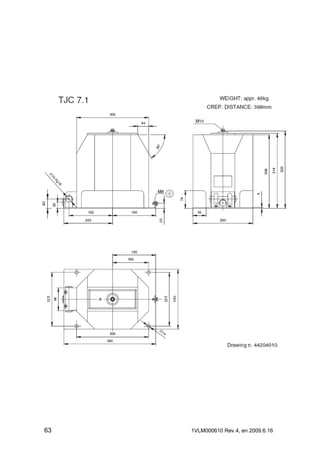
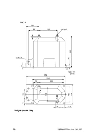
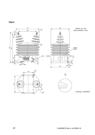
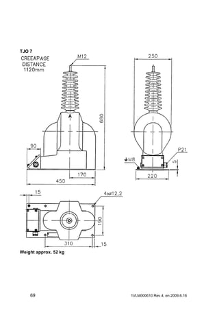
The mounting position of the outdoor transformer is only horizontal. The other position
can be agreed with the supplier. The transformer is fixed using the mounting base (VT) with
four screws M10 and washers or two U profiles (CT) with M12 screws. Fastening must be
done on a smooth surface.
There is a M12 screw for grounding of current transformer and M8 screw for grounding
of voltage transformer.
Primary connection
Primary terminals of the current transformer are made of cooper and they are silver or
tin plated. There are M12 screws used for fastening of primary conductor to the terminal. For
primary reconnectable transformers the ratio can be reconnected by changing position of the
links fixed by M8 screws without removing already fitted primary conductors.
Maximum allowed torques for screw connections of current transformers:
Screw
Max. torque [Nm]
Min. torque [Nm]
M5
3.5
2.8
M6
4
3
M8
20
16
M10
20
16
M12
70
56
Maximum allowed torque for screw connection of voltage transformer is 20 Nm.
Maximum allowed cantilever strength is: Voltage transformers 2000 N.
Current transformers 5000 N.
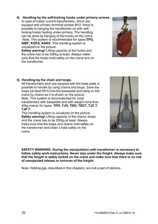
In case of Bus CT, there must be
always connected CT shielding to
the primary bar. Connection must
be done at least on one side of
the CT. One example of KOKS
12 shielding connection is
described on the picture
6
1VLM000610 Rev.4, en 2009.6.16](https://image.slidesharecdn.com/abb-transformers-mv-medium-voltage-transformers-guide-140217084343-phpapp01/85/ABB-Medium-Voltage-MV-Indoor-and-Outdoor-Current-Transformers-ABB-CT-s-Current-Transformers-ABB-TTR-ABB-TPU-ABB-TPE-ABB-KON-17-ABB-TPO6-6-320.jpg)


The document provides comprehensive instructions on the installation, usage, and maintenance of current and voltage instrument transformers, detailing service conditions, technical specifications, and safety guidelines. It emphasizes the importance of proper grounding and connection practices to ensure safe operation, as well as maintenance protocols to keep the transformers in optimal condition. Additionally, the document references normative standards relevant to the transformers and includes appendices with examples and diagrams for clarity.