Downloaded 475 times
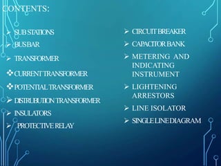
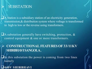
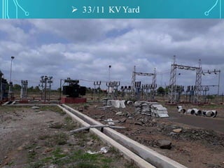
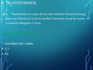
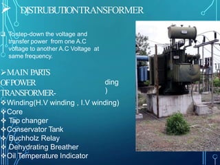
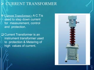
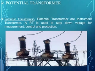
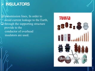
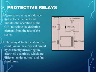
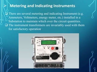
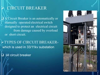
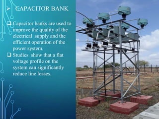
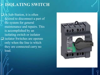
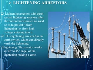
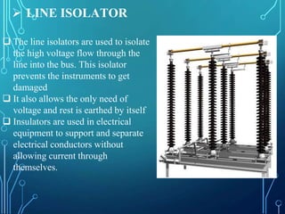
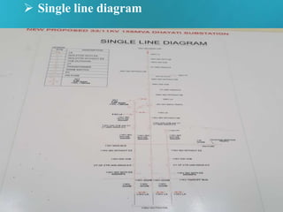


This document provides an overview of a presentation on a 33/11 kV substation. It discusses key components of the substation including transformers, busbars, distribution transformers, current and potential transformers, protective relays, circuit breakers, capacitor banks, insulators, metering instruments, lightning arrestors, and isolators. The presentation also includes a single line diagram of the substation layout.


![Summer_Tranning_satihs[1].pptx](https://cdn.slidesharecdn.com/ss_thumbnails/summertranningsatihs1-221218101756-30b4a4a4-thumbnail.jpg?width=640&height=640&fit=bounds)