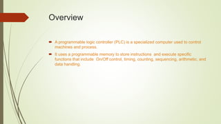
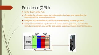
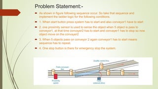
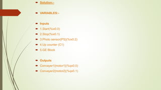
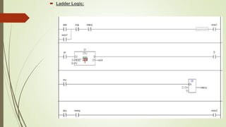
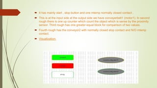
A Presentation on PLC.
Dhruvit Kharadi (12bee023)
Nirmit Pandav (12bee029)
Overview
 A programmable logic controller (PLC) is a specialized computer used to control
machines and process.
 It uses a programmable memory to store instructions and execute specific
functions that include On/Off control, timing, counting, sequencing, arithmetic, and
data handling.
Processor (CPU)
 Is the “brain” of the PLC.
 Consists of a microprocessor for implementing the logic, and controlling the
communications among the modules.
 Designed so the desired circuit can be entered in relay ladder logic form.
 The processor accepts input data from various sensing devices, executes the
stored user program, and sends appropriate output commands to control devices.
PLC Operating Cycle
 During each operating cycle, the controller examines the status of input devices,
executes the user program, and changes outputs accordingly.
The completion of one cycle
of this sequence is called
a scan. The scan time, the
time required for one full
cycle, provides a measure
of the speed of response
of the PLC.
Programming language
 Ladder logic
 Function block
 Instruction list
Problem Statement:-
 As shown in figure following sequence occur. So take that sequence and
implement the ladder logic for the following conditions.
 1. When start button press system has to start and also conveyor1 have to start
 2. one proximity sensor is used to sense the object when 5 object is pass to
conveyor1, at that time convayer2 has to start and convayer1 has to stop so now
object move on the convayer2
 3. When 5 objects pass on conveyor 2 again conveyor1 has to start means
sequence has to repeat.
 4. One stop button is there for emergency stop the system.
 Solution:-
 VARIABLES:-
 Inputs
 1.Start(%ix0.0)
 2.Stop(%ix0.1)
 3.Photo sensor{PS}(%ix0.2)
 4.Up counter (C1)
 5.GE Block
 Outputs
 Convayer1{motor1}(%qx0.0)
 Convayer2{motor2}(%qx0.1)
LOGIC
 When start button press at that time system has start. Same time conveyor1 has
started now object are move on the conveyer belt 1 so that object is sense by the
photo sensor. Now there is a one up counter C1 which will count the object which
will pass onto the conveyor1
 There is one greater equal block which has 5 as preset value and one value we
get from counter so this two value that will compare and when count value is same
or more then preset value means 5 or more then 5 at that time convaeyor1 is stop
and conveyor2 will start now.
 Now when 5 objects pass on the conveyor belt 2 automatically conveyor belt 1 is
start means now process is repeat automatically.
 When stop button is pressed in any emergency condition at that time whole the
system stop as stop button is master stop button o the system.
 Ladder Logic:
 It has mainly start , stop button and one mtemp normally closed contact .
 This is at the input side at the output side we have convayerbelt1 (motor1). In second
rough there is one up counter which count the object which is sense by the proximity
sensor. Third rough has one greater equal block for comparison of two values.
 Fourth rough has the conveyor2 with normally closed stop contact and N/O mtemp
contact.
 Visualization:
 Visualization has mainly 5 things
 1. start switch to start the whole system as well as conveyorbelt1
 2. stop switch to stop the whole system
 3. proximity sensor to sense the object
 4.conveyor belt1
 5.conveyor belt2

A Presentation on Automatic conveyor belt system

  • 1.
    A Presentation onPLC. Dhruvit Kharadi (12bee023) Nirmit Pandav (12bee029)
  • 2.
    Overview  A programmablelogic controller (PLC) is a specialized computer used to control machines and process.  It uses a programmable memory to store instructions and execute specific functions that include On/Off control, timing, counting, sequencing, arithmetic, and data handling.
  • 3.
    Processor (CPU)  Isthe “brain” of the PLC.  Consists of a microprocessor for implementing the logic, and controlling the communications among the modules.  Designed so the desired circuit can be entered in relay ladder logic form.  The processor accepts input data from various sensing devices, executes the stored user program, and sends appropriate output commands to control devices.
  • 4.
    PLC Operating Cycle During each operating cycle, the controller examines the status of input devices, executes the user program, and changes outputs accordingly. The completion of one cycle of this sequence is called a scan. The scan time, the time required for one full cycle, provides a measure of the speed of response of the PLC.
  • 5.
    Programming language  Ladderlogic  Function block  Instruction list
  • 6.
    Problem Statement:-  Asshown in figure following sequence occur. So take that sequence and implement the ladder logic for the following conditions.  1. When start button press system has to start and also conveyor1 have to start  2. one proximity sensor is used to sense the object when 5 object is pass to conveyor1, at that time convayer2 has to start and convayer1 has to stop so now object move on the convayer2  3. When 5 objects pass on conveyor 2 again conveyor1 has to start means sequence has to repeat.  4. One stop button is there for emergency stop the system.
  • 7.
     Solution:-  VARIABLES:- Inputs  1.Start(%ix0.0)  2.Stop(%ix0.1)  3.Photo sensor{PS}(%ix0.2)  4.Up counter (C1)  5.GE Block  Outputs  Convayer1{motor1}(%qx0.0)  Convayer2{motor2}(%qx0.1)
  • 8.
    LOGIC  When startbutton press at that time system has start. Same time conveyor1 has started now object are move on the conveyer belt 1 so that object is sense by the photo sensor. Now there is a one up counter C1 which will count the object which will pass onto the conveyor1  There is one greater equal block which has 5 as preset value and one value we get from counter so this two value that will compare and when count value is same or more then preset value means 5 or more then 5 at that time convaeyor1 is stop and conveyor2 will start now.  Now when 5 objects pass on the conveyor belt 2 automatically conveyor belt 1 is start means now process is repeat automatically.  When stop button is pressed in any emergency condition at that time whole the system stop as stop button is master stop button o the system.
  • 9.
  • 10.
     It hasmainly start , stop button and one mtemp normally closed contact .  This is at the input side at the output side we have convayerbelt1 (motor1). In second rough there is one up counter which count the object which is sense by the proximity sensor. Third rough has one greater equal block for comparison of two values.  Fourth rough has the conveyor2 with normally closed stop contact and N/O mtemp contact.  Visualization:
  • 11.
     Visualization hasmainly 5 things  1. start switch to start the whole system as well as conveyorbelt1  2. stop switch to stop the whole system  3. proximity sensor to sense the object  4.conveyor belt1  5.conveyor belt2