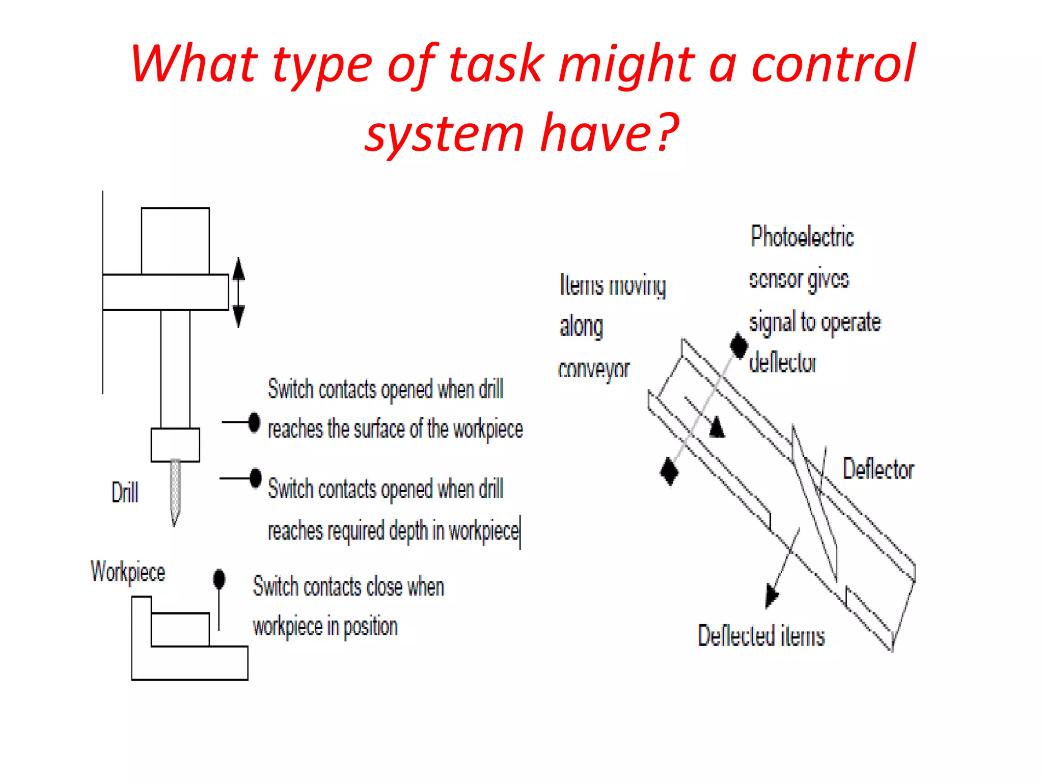
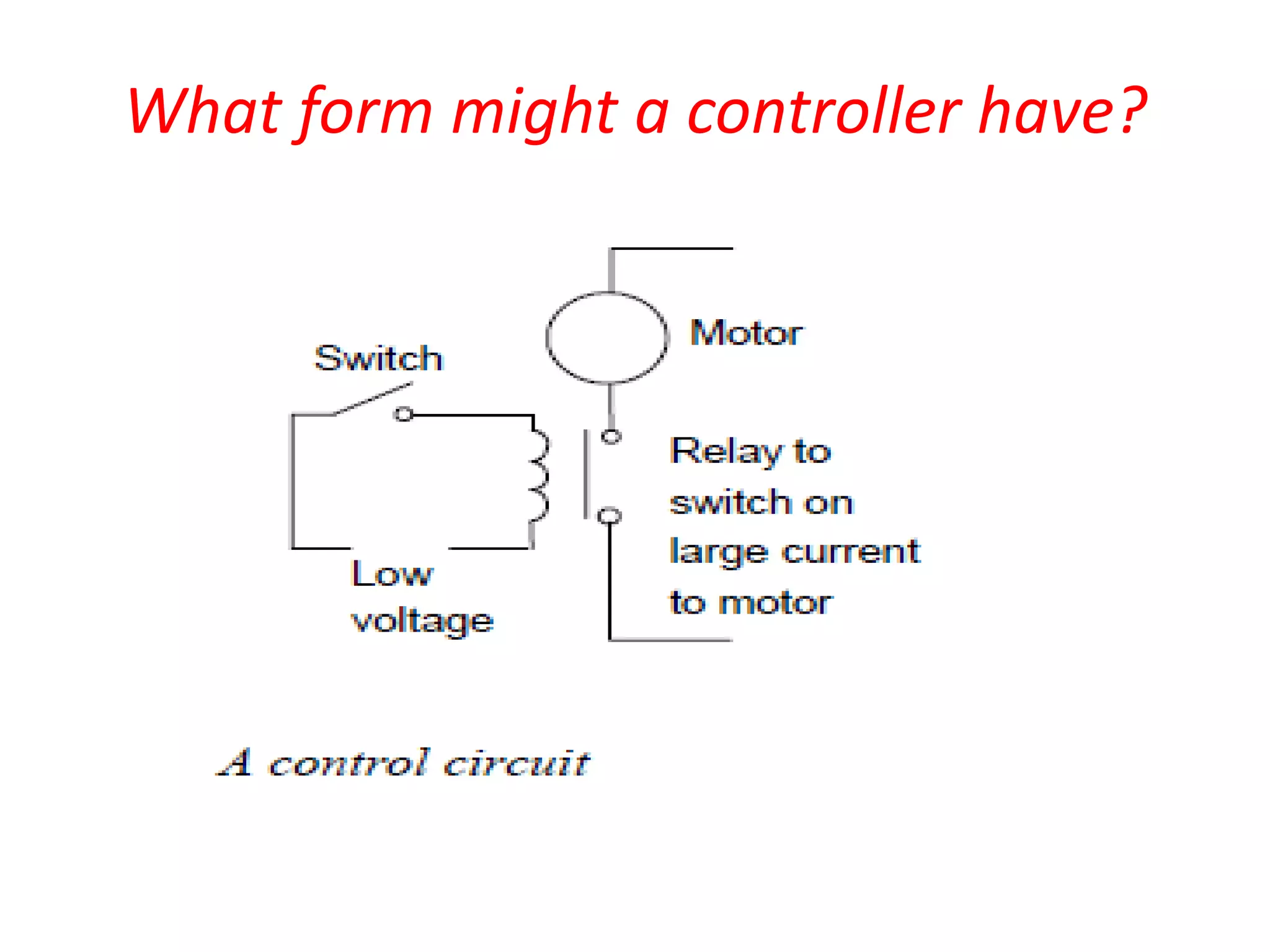
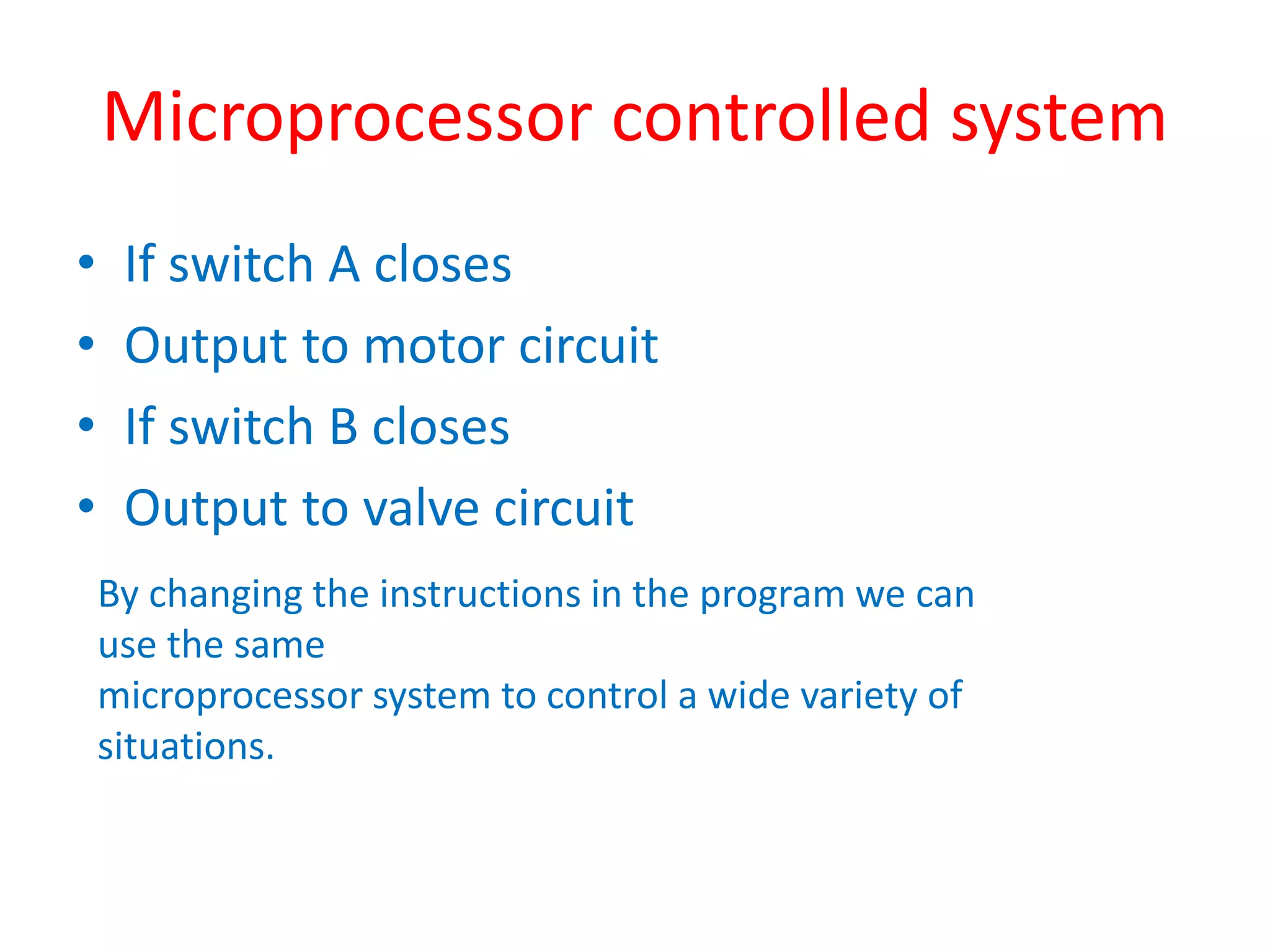
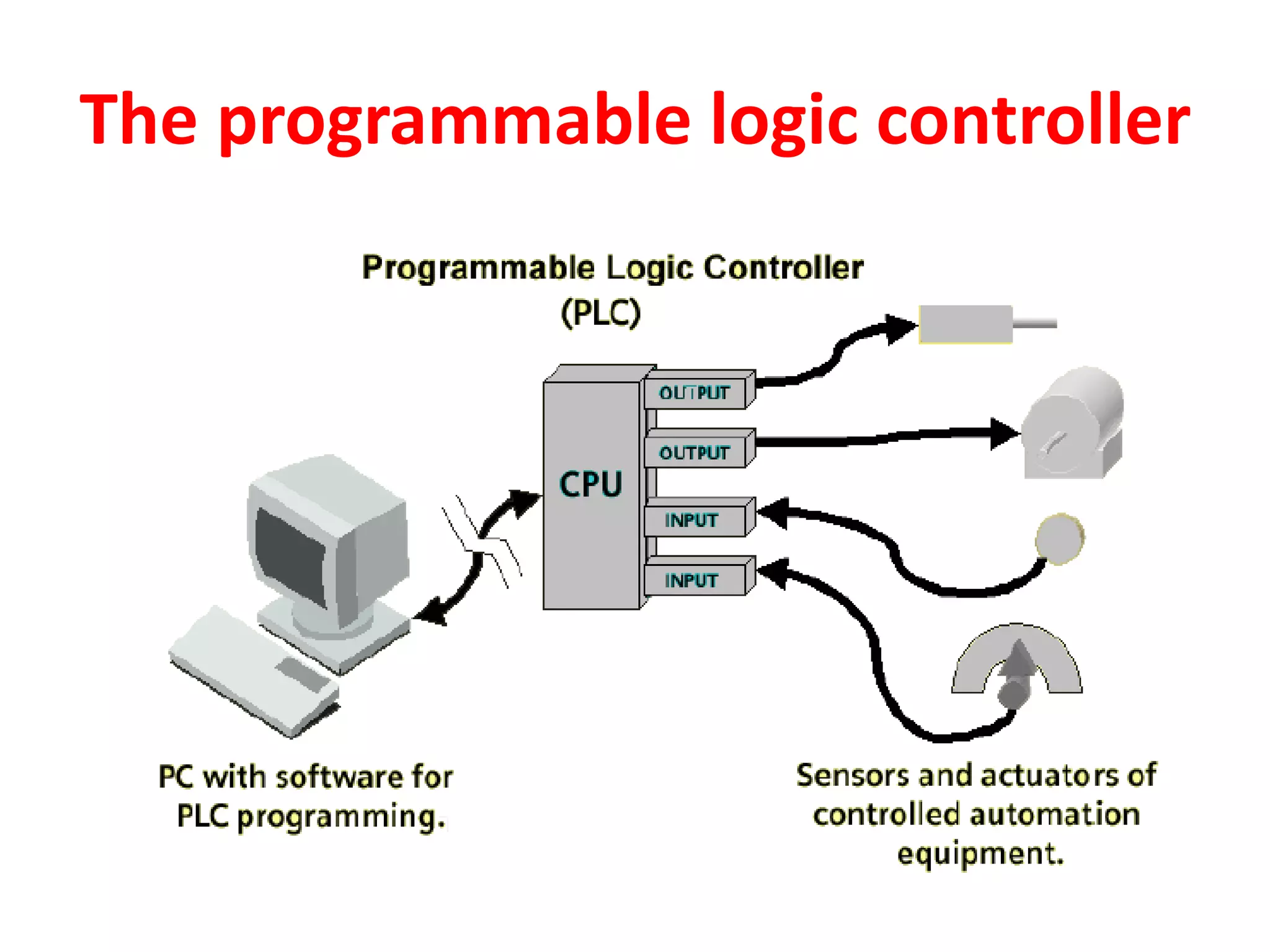
1. A control system uses a microprocessor-based programmable logic controller (PLC) to receive inputs from sensors, execute a stored program to process the inputs, and output control signals to devices like motors and valves.
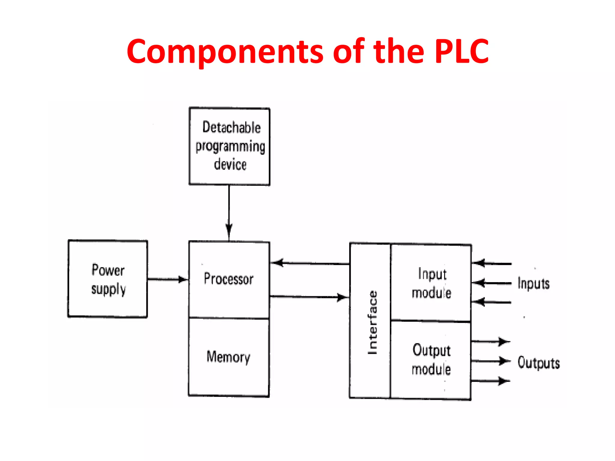
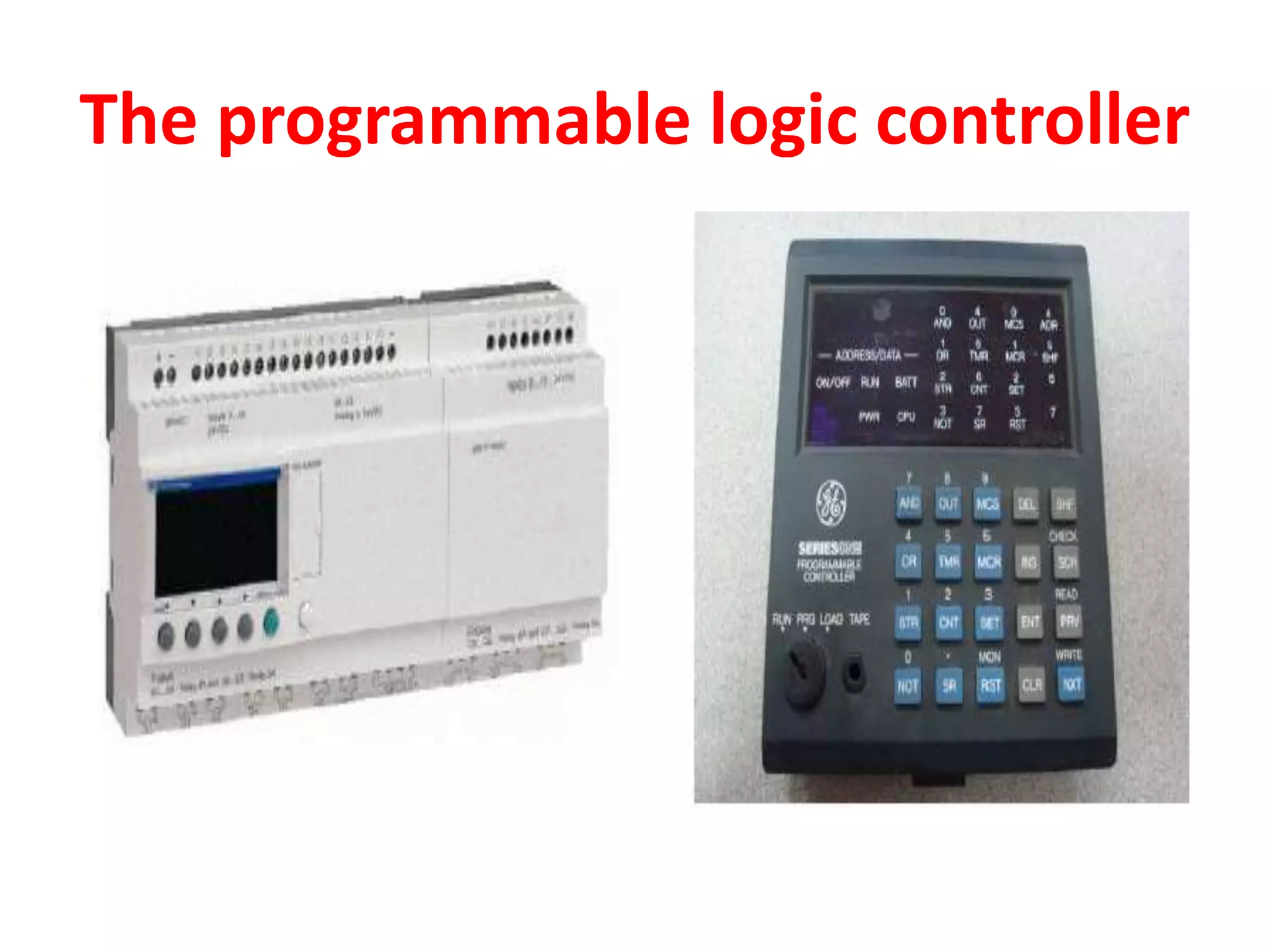
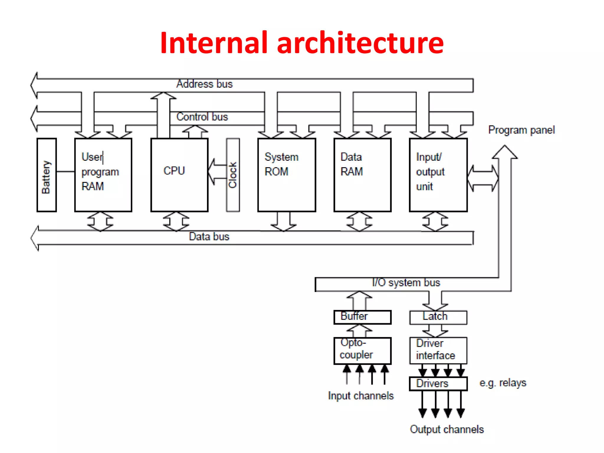
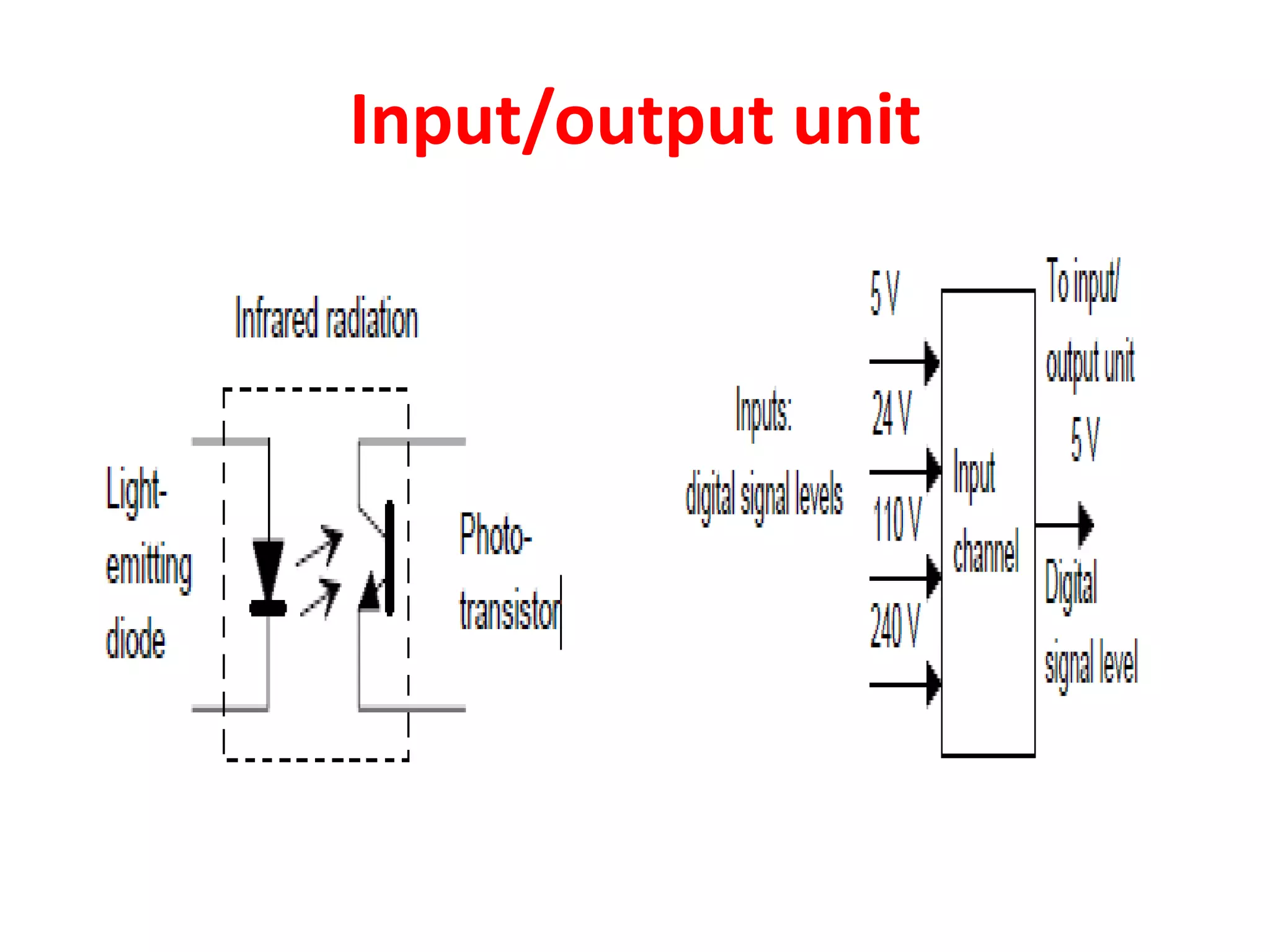
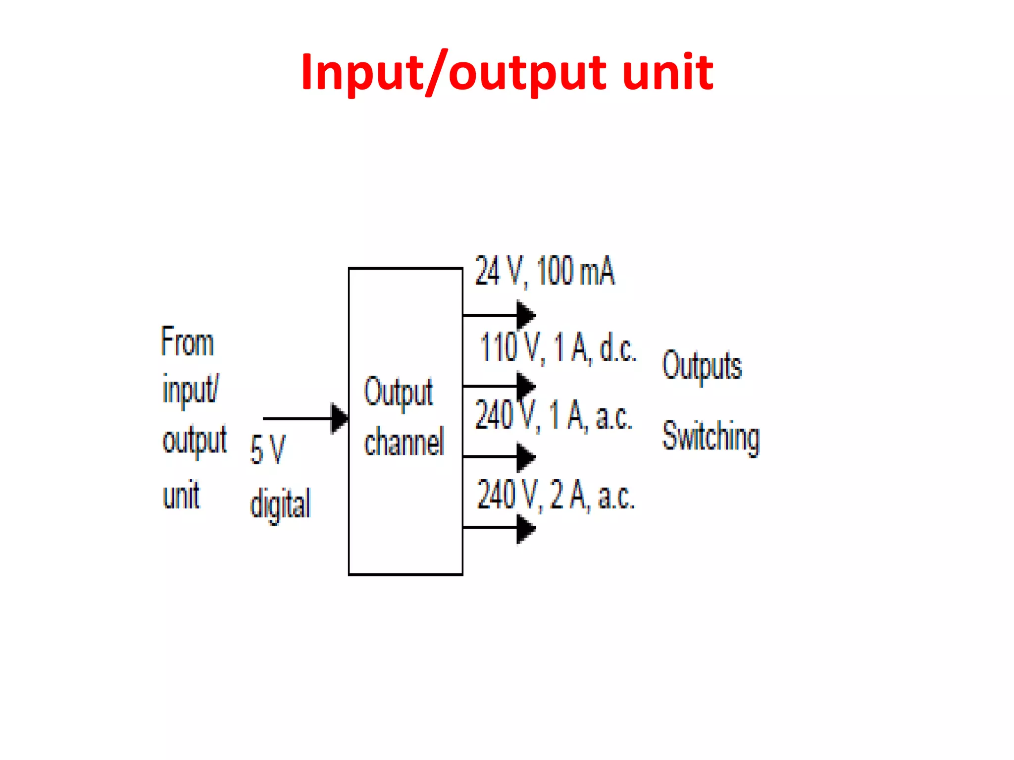
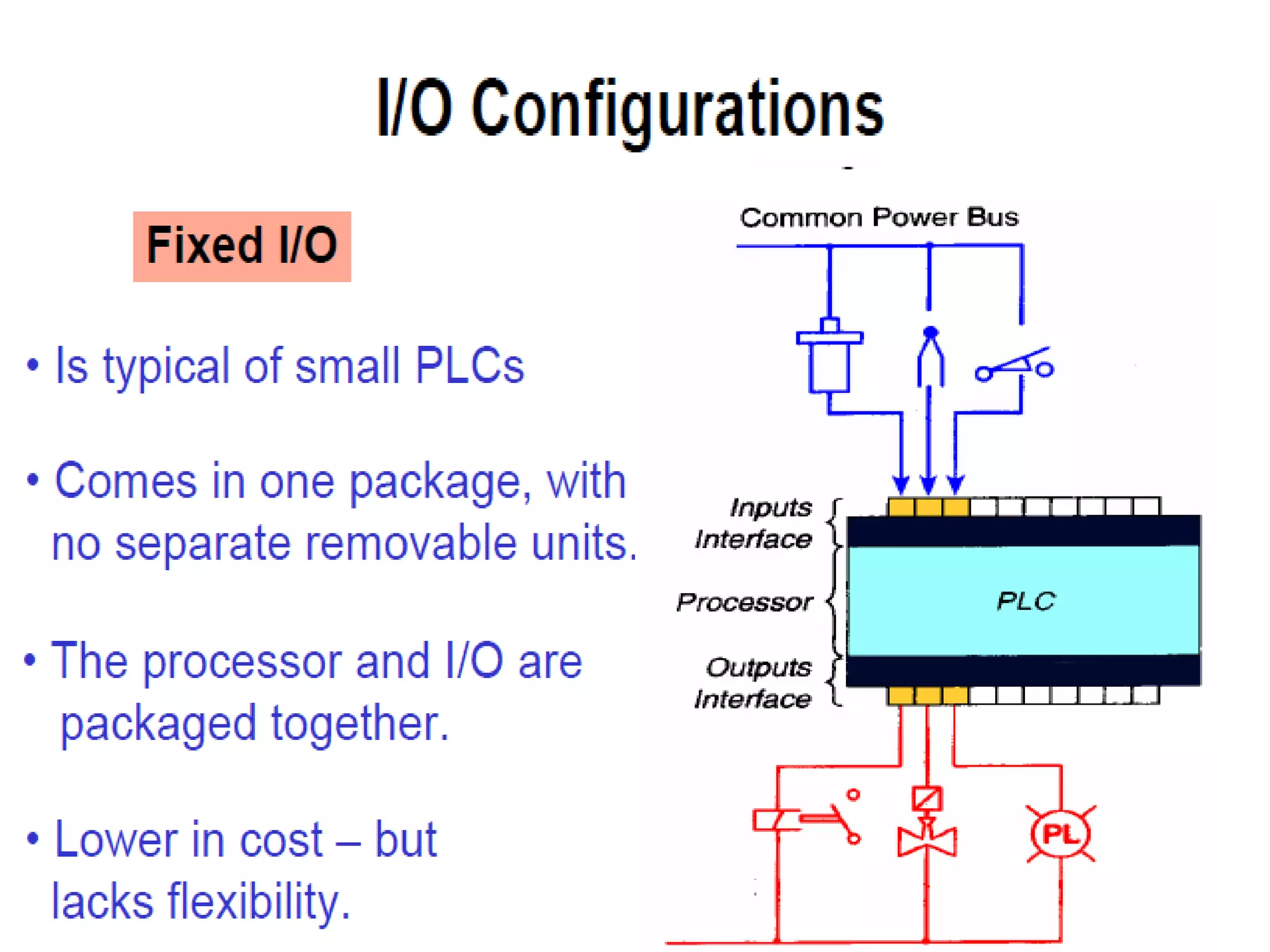
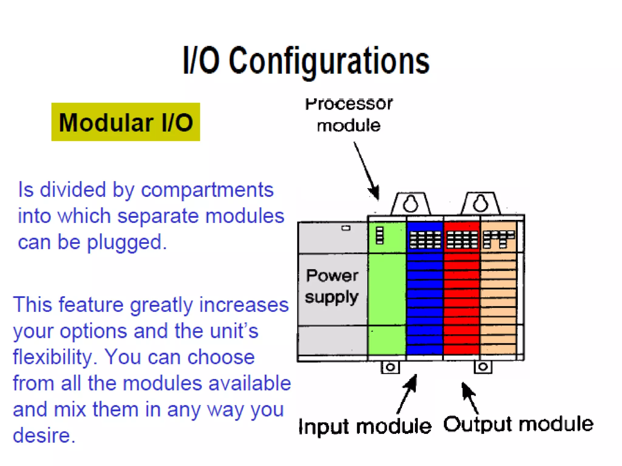
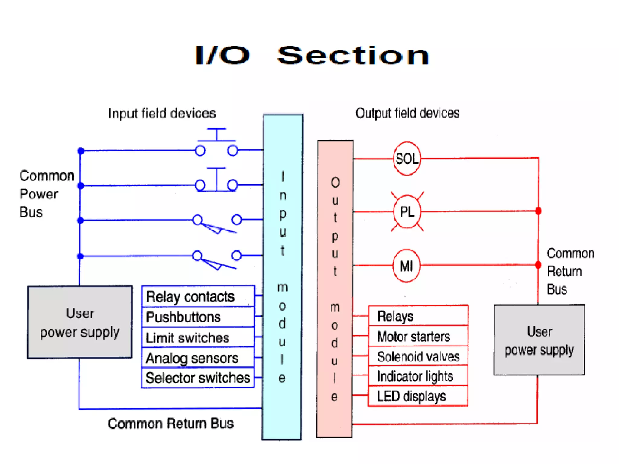
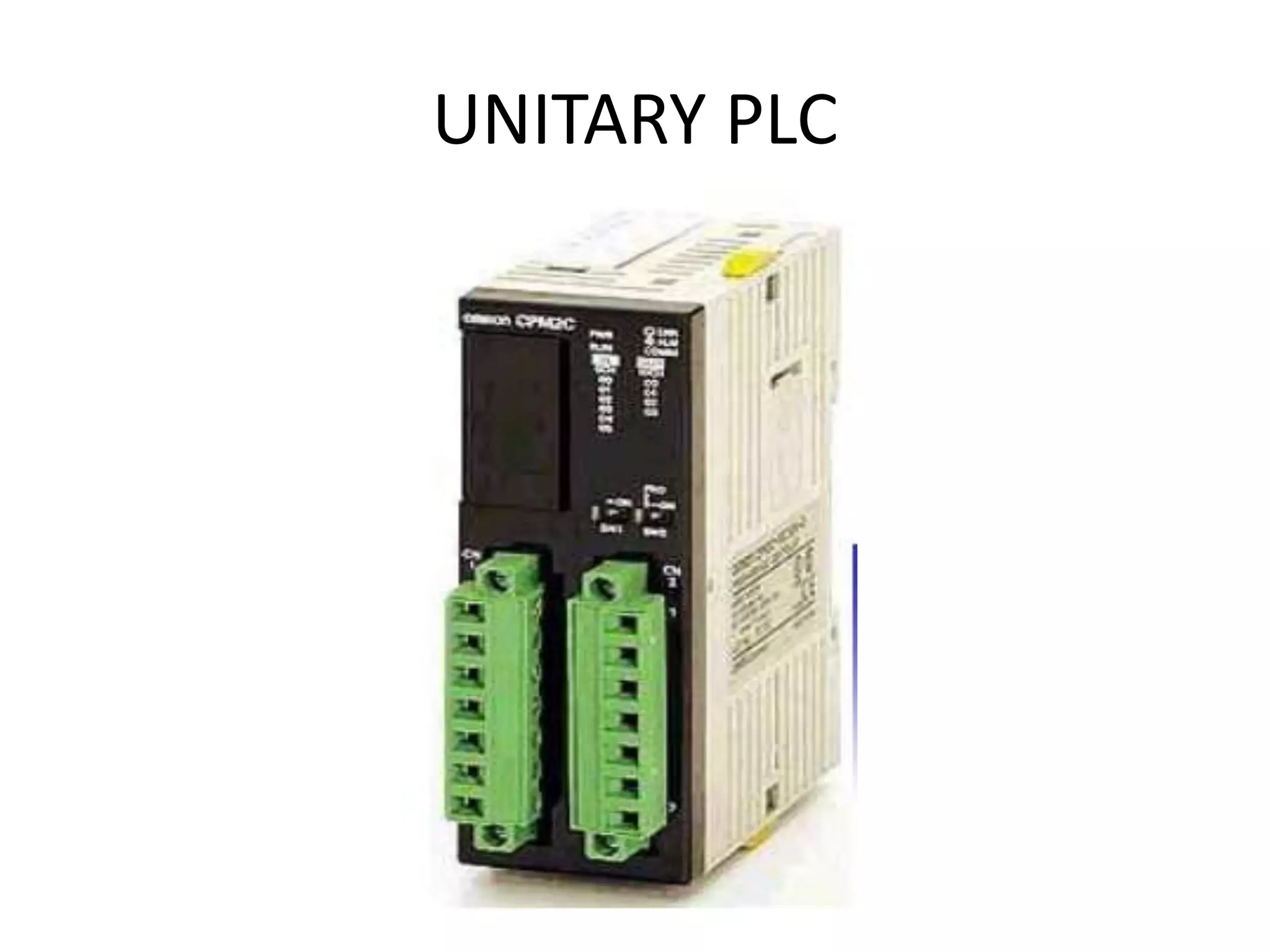
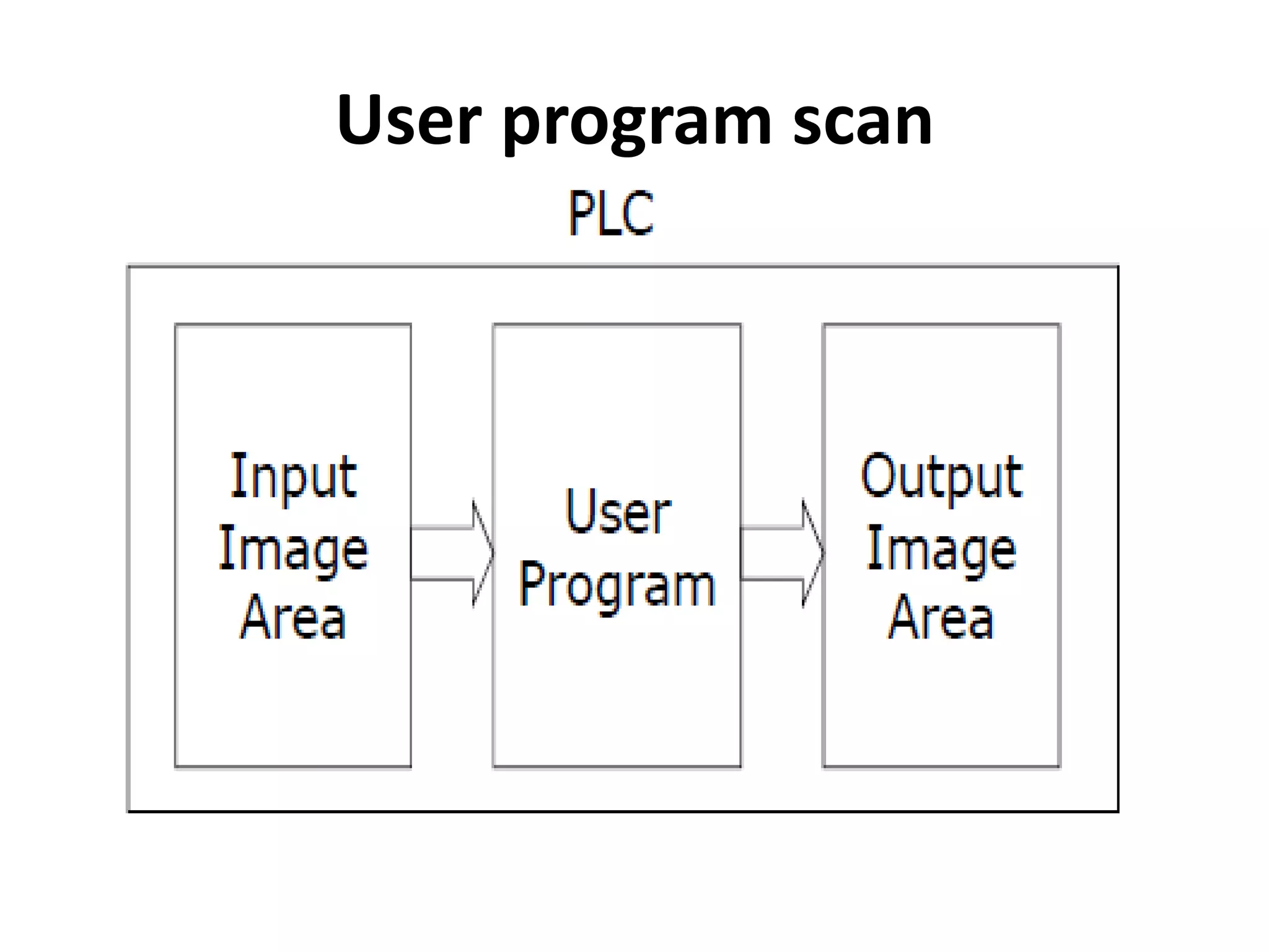
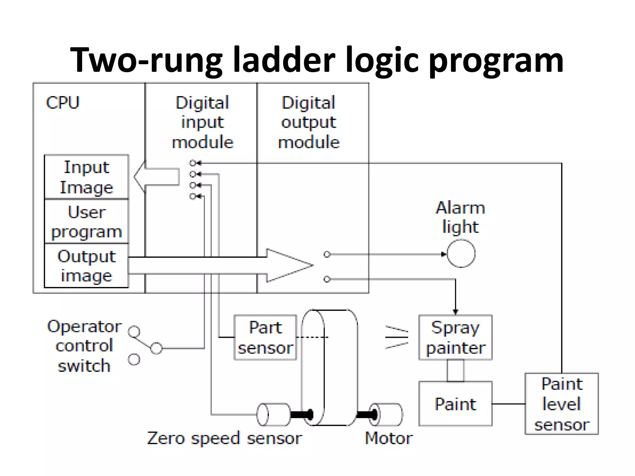
2. A PLC consists of a central processing unit, memory to store the user program, and input/output modules to interface with sensors and devices. It executes programs by doing repeated scan cycles of input, program, and output stages.
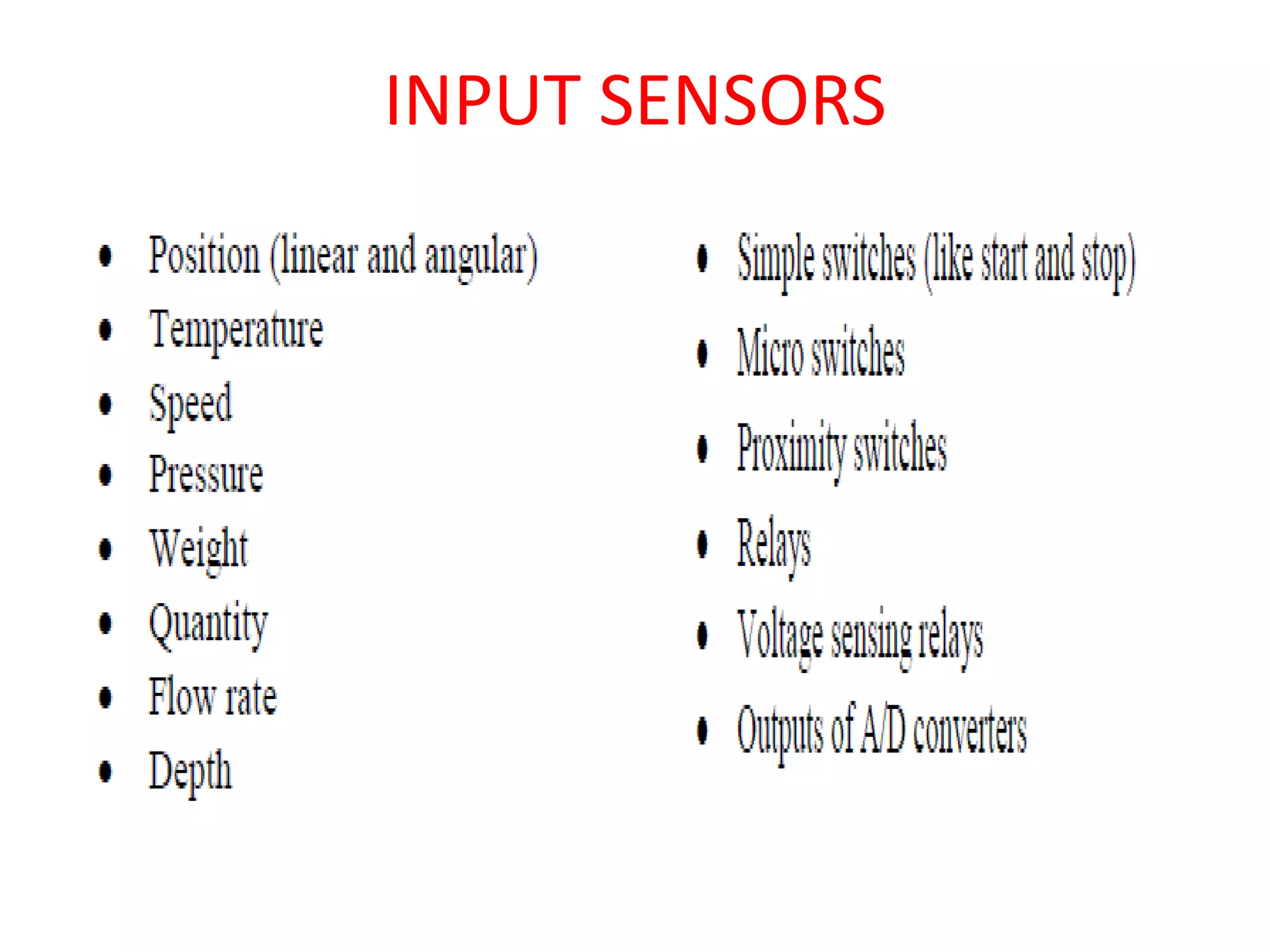
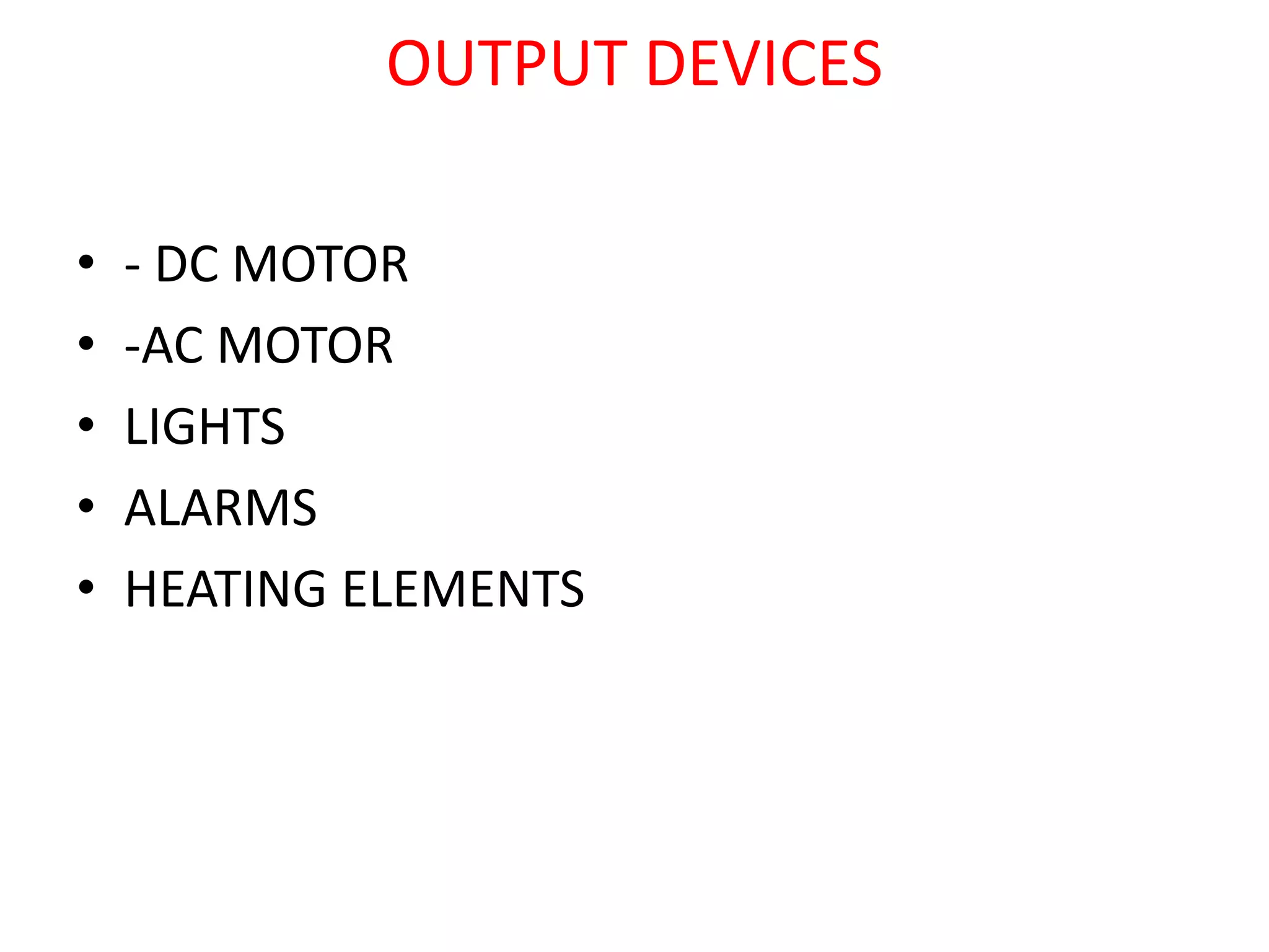
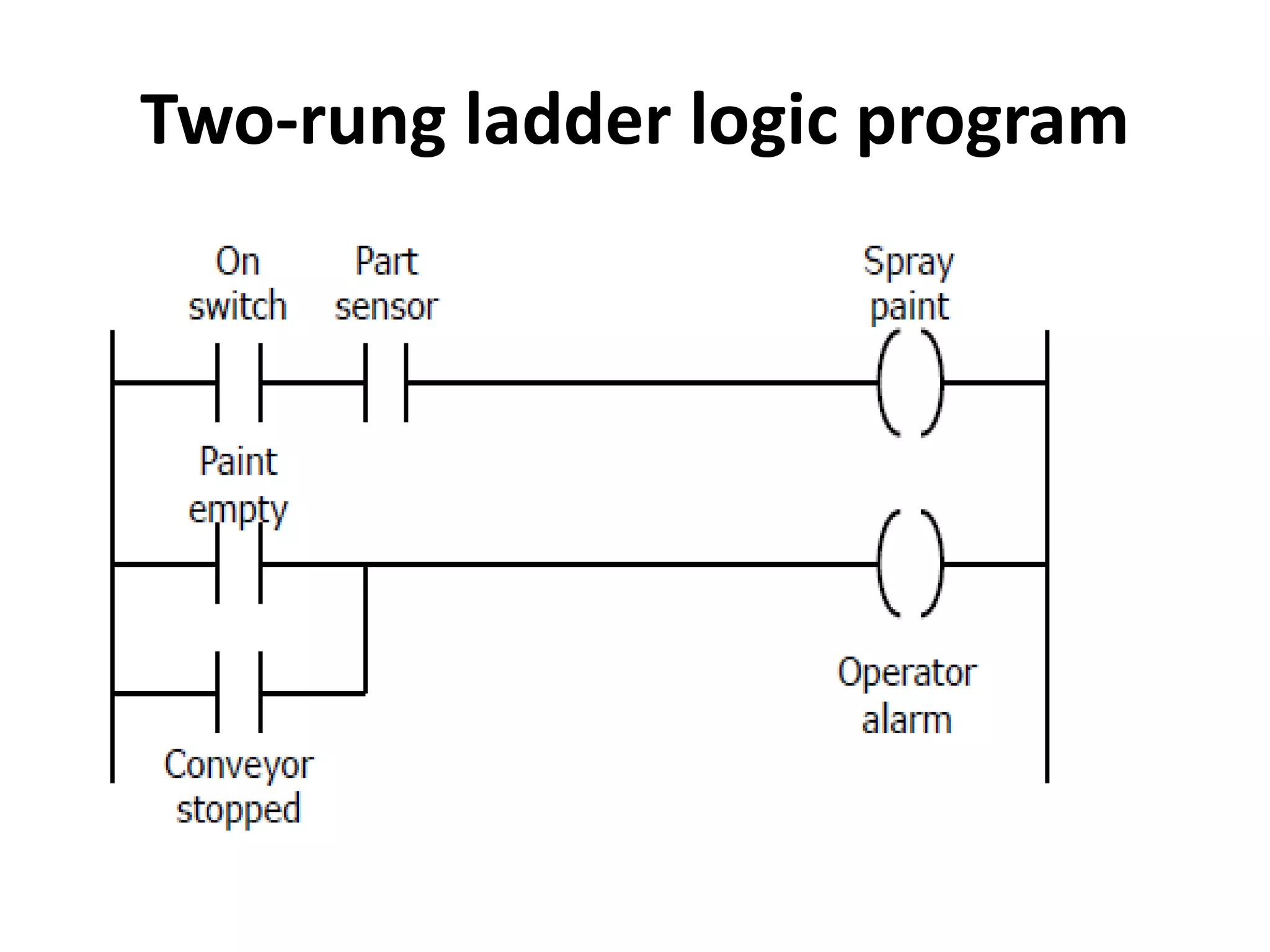
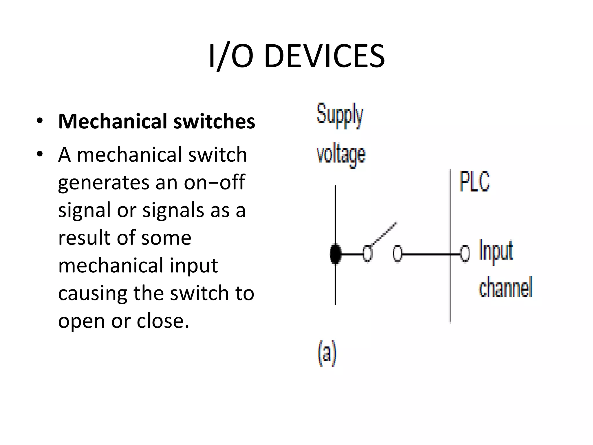
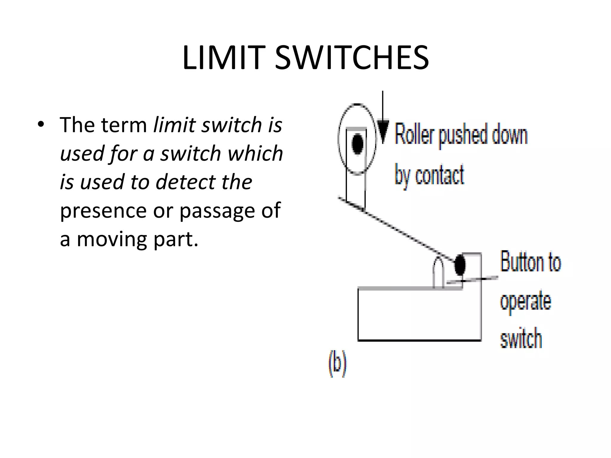
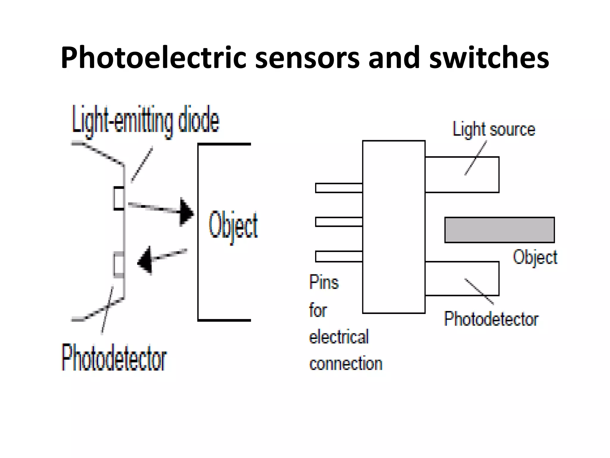
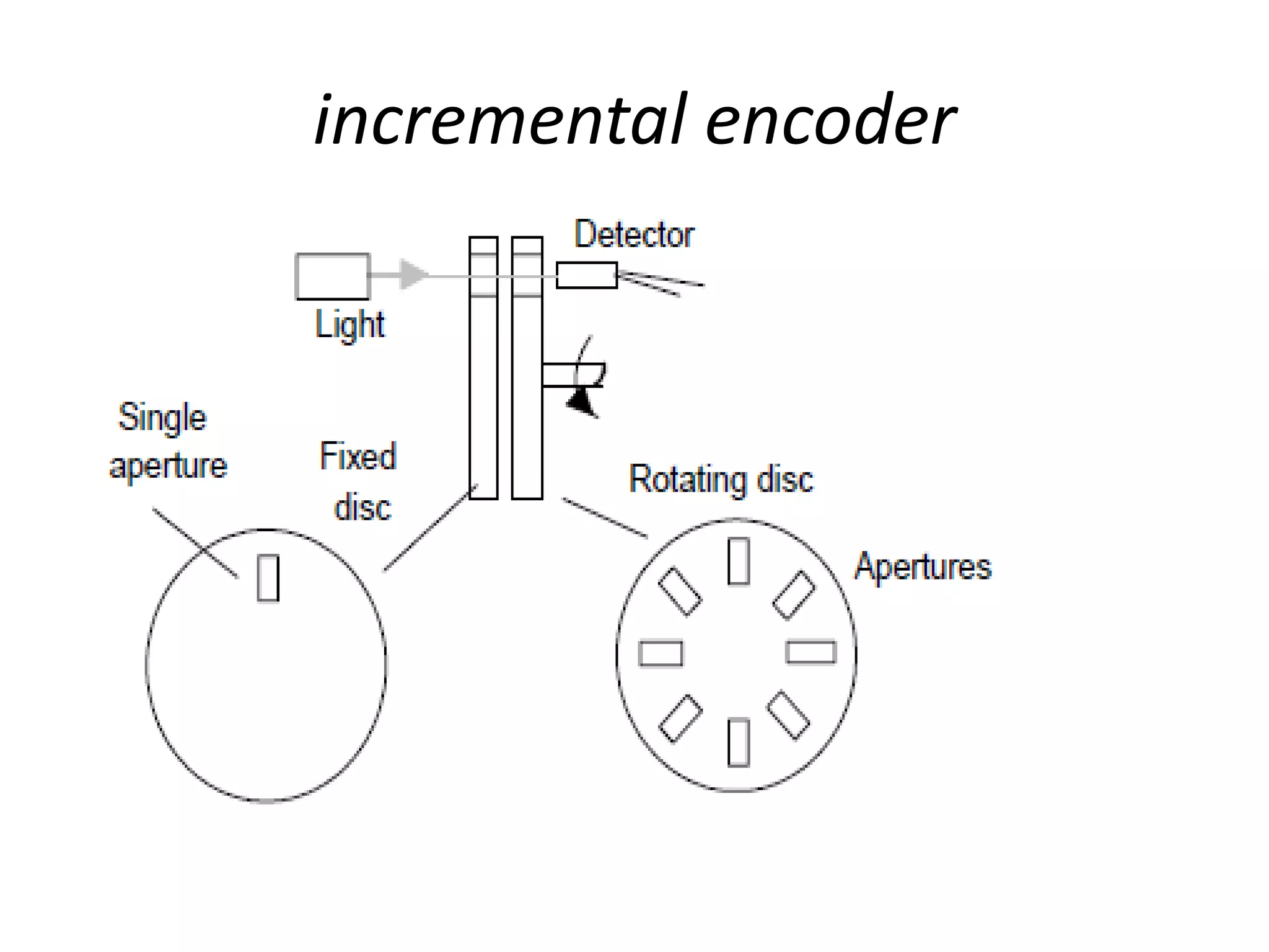
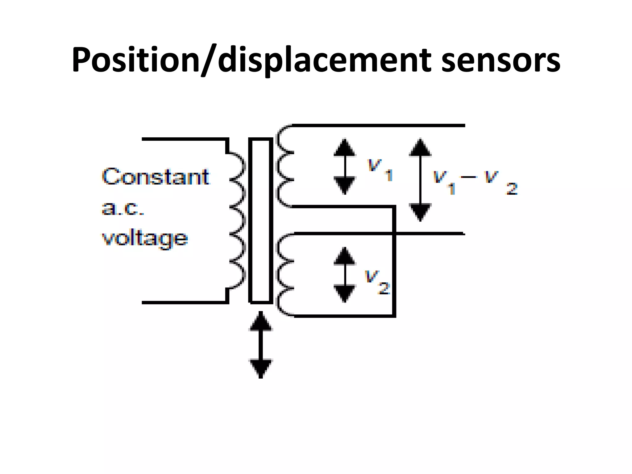
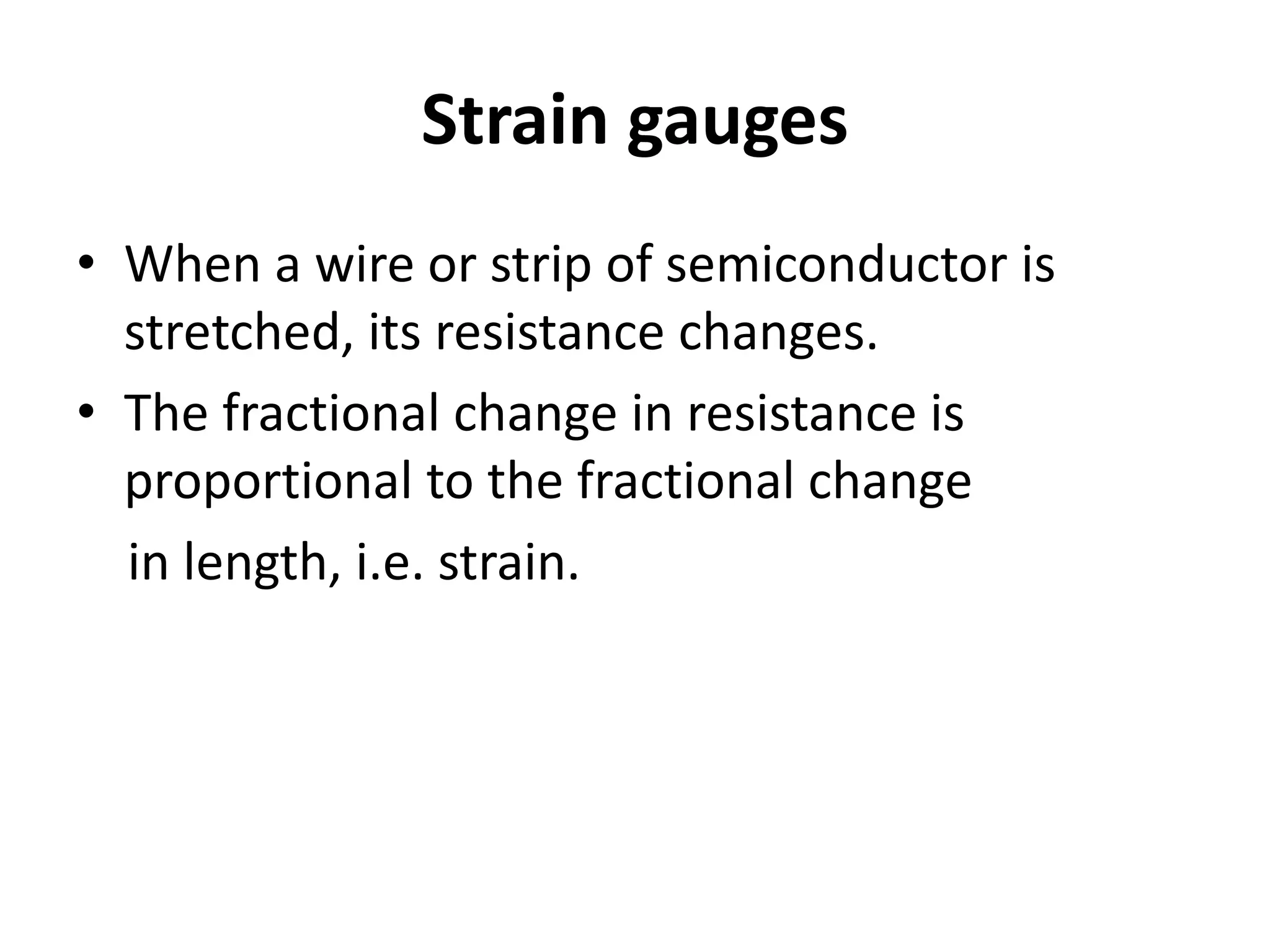
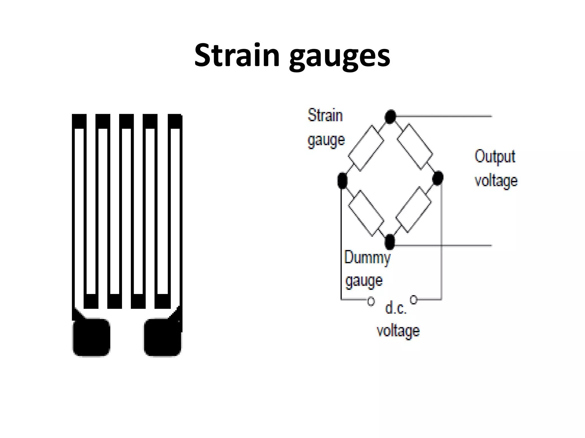
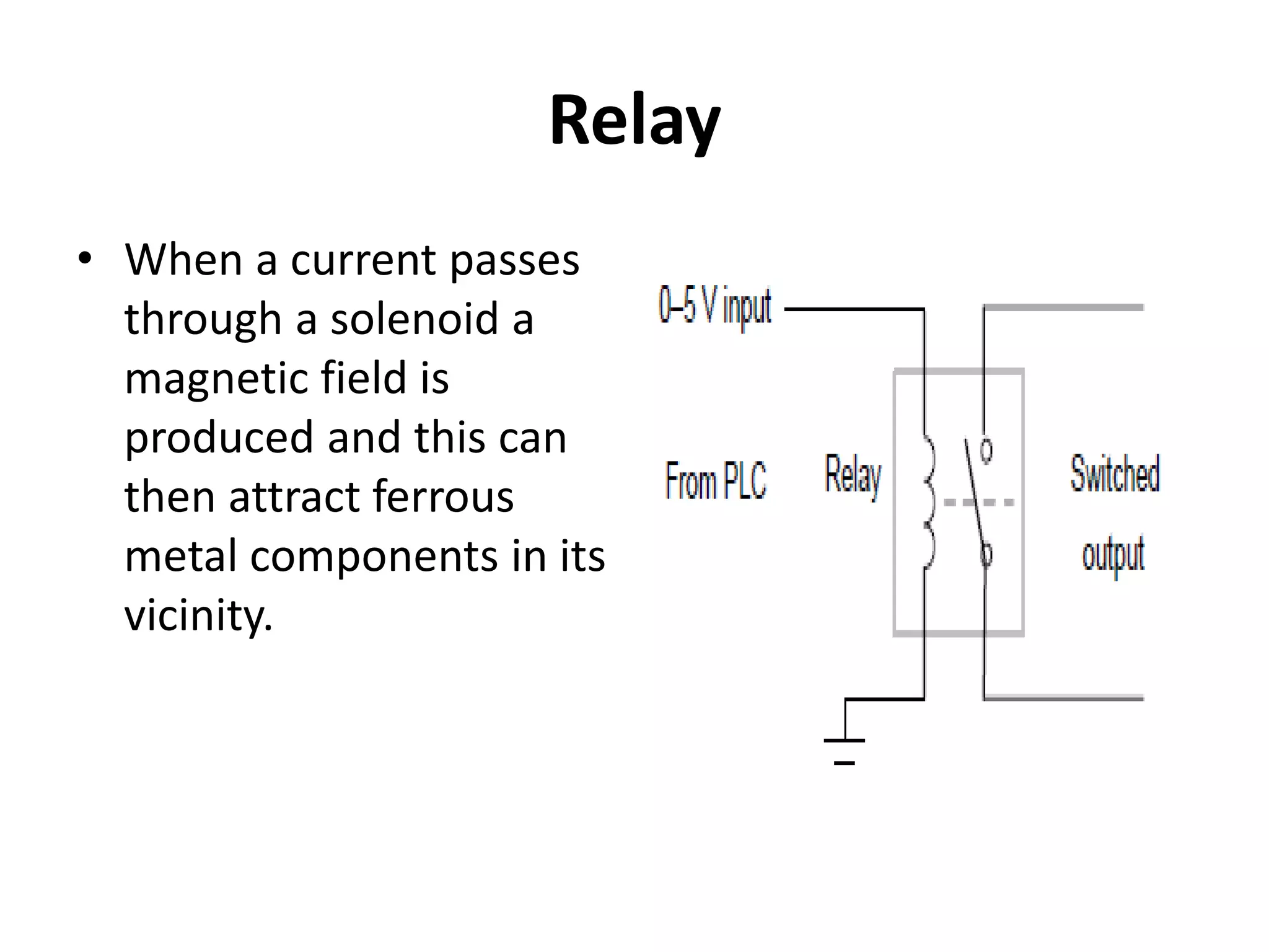
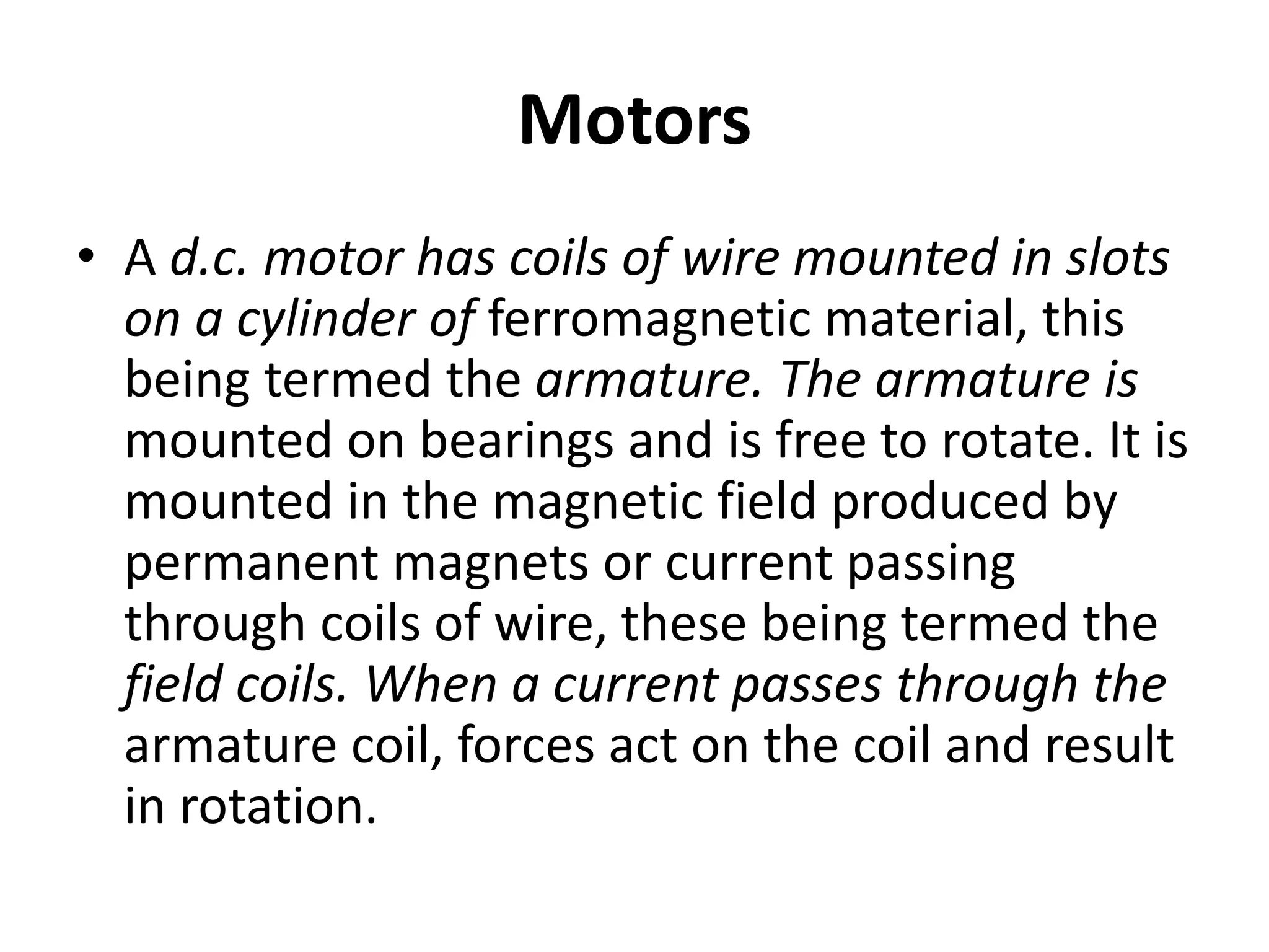
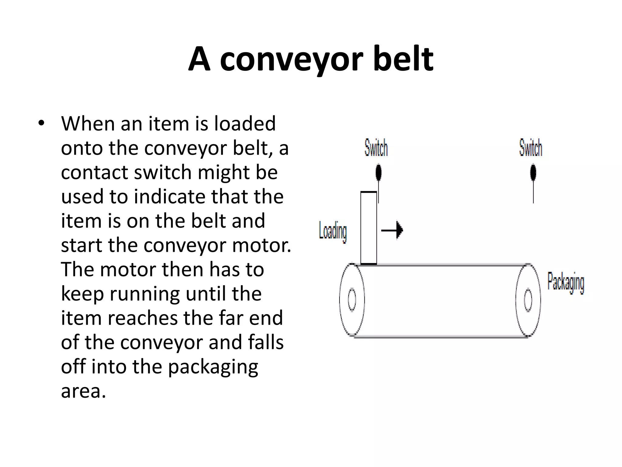
3. Common sensors that provide inputs to a PLC include limit switches, photoelectric sensors, encoders, temperature sensors, and pressure sensors. Common devices controlled by PLC outputs include motors, solenoids, and conveyor belts.


![PLC Ladder Programming [Mechatronics]](https://cdn.slidesharecdn.com/ss_thumbnails/plc-ppt-snteli-200503070616-thumbnail.jpg?width=640&height=640&fit=bounds)